How does it work?
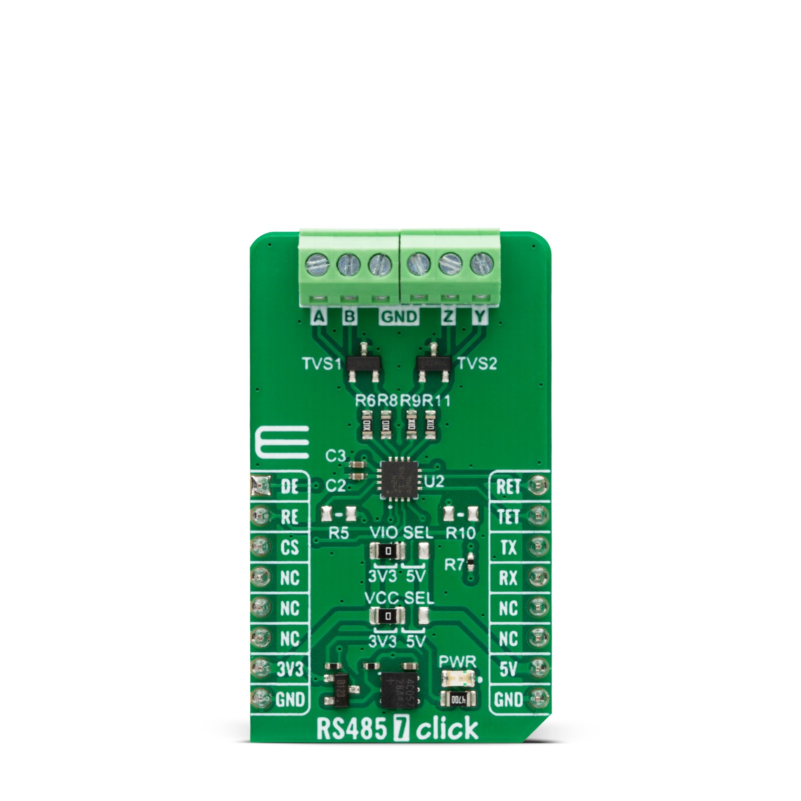
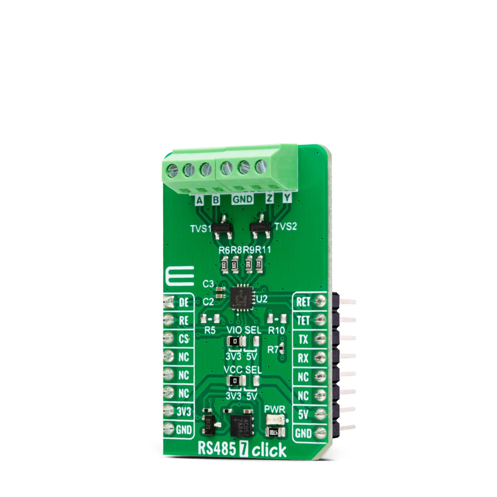
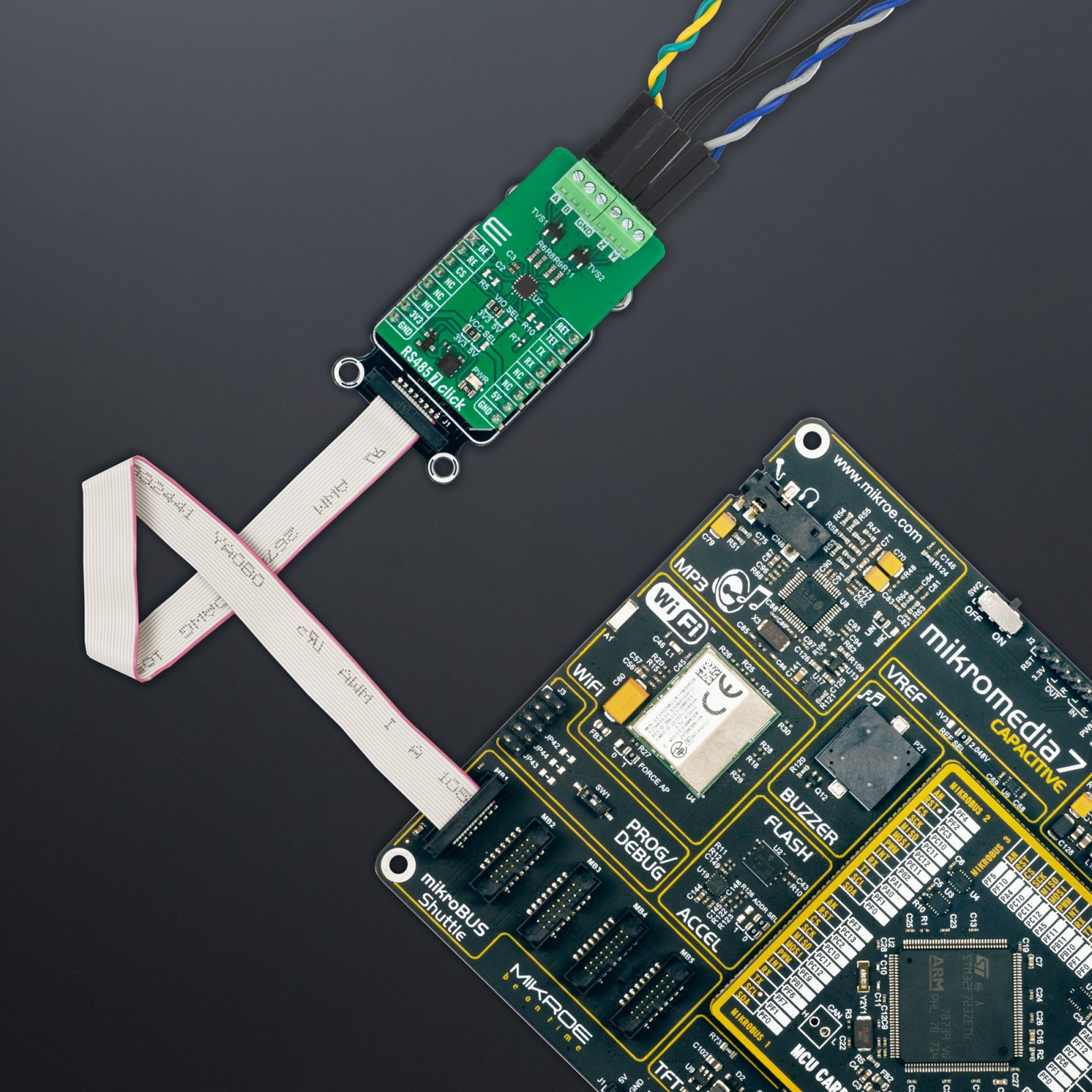
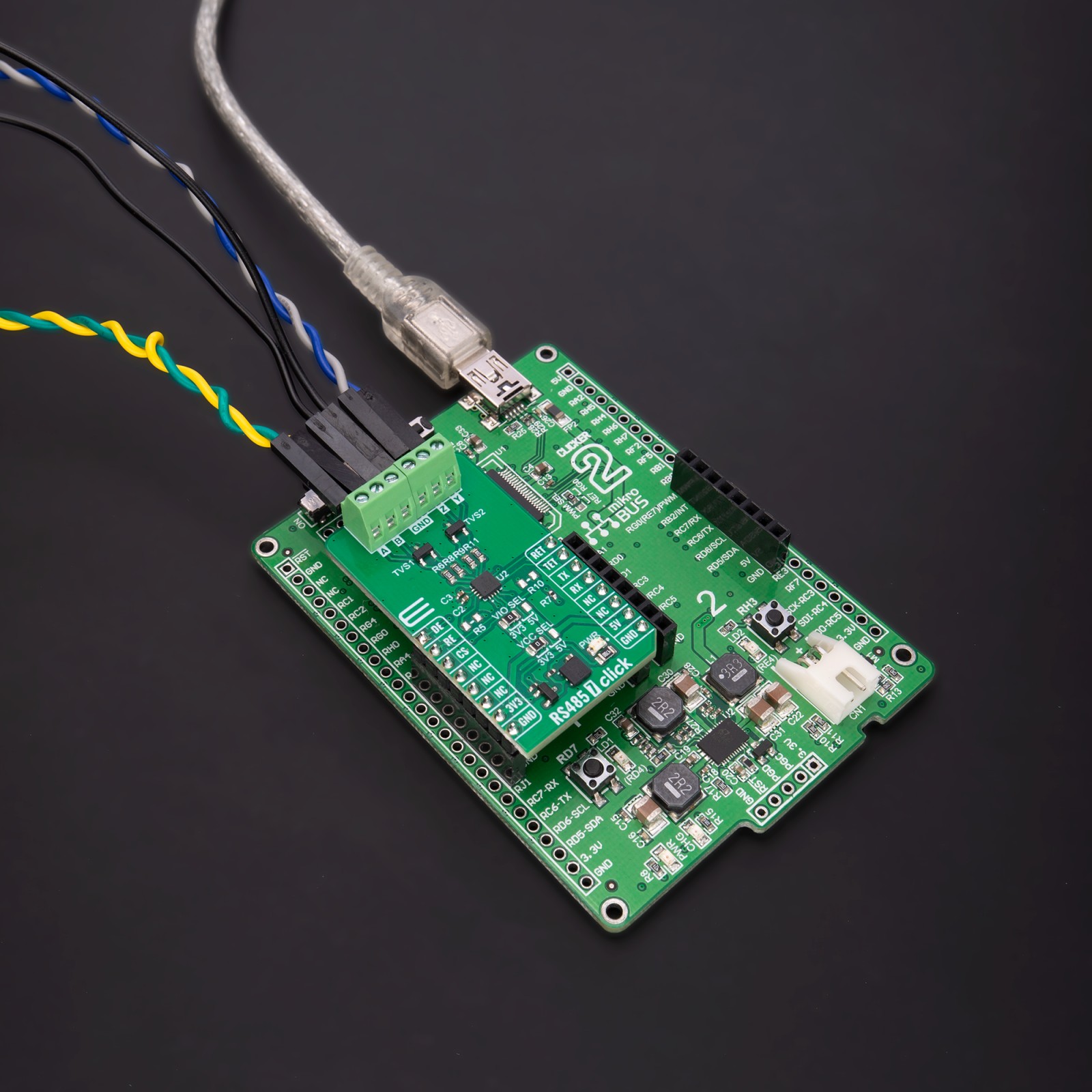
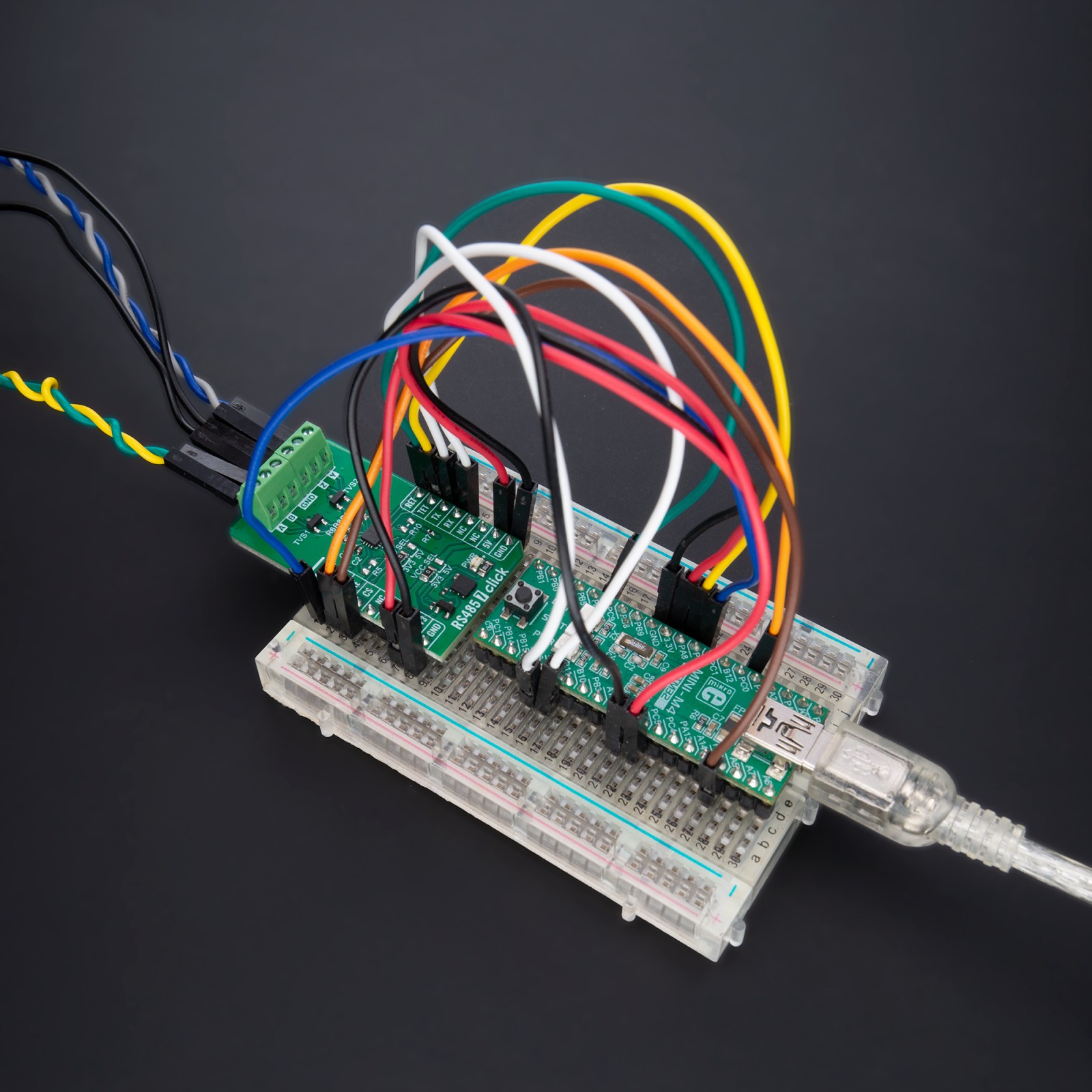
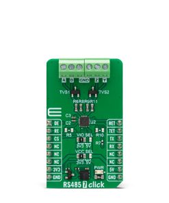
RS485 7 Click is based on the THVD1424, a flexible RS-485 transceiver from Texas Instruments for asynchronous data transmissions. The THVD1424 has two termination resistors of nominal 120Ω, one across Y/Z and another across A/B. Both termination resistors are enabled or disabled using pins RET and TET pins of the mikroBUS™ socket, routed to the default positions of PWM and INT pins of the mikroBUS™ socket. Both termination resistors can be enabled or disabled, independent of the state of the driver or receiver. Termination is OFF if the device is unpowered or in thermal shutdown. Internal ESD protection circuits protect the transceiver against Electrostatic Discharges (ESD) according to IEC 61000-4-2 of up to ±8kV (Contact Discharge), ±15kV (Air Gap Discharge), and against electrical-fast-transients (EFT) according to IEC 61000-4-4 of up to ±4kV.
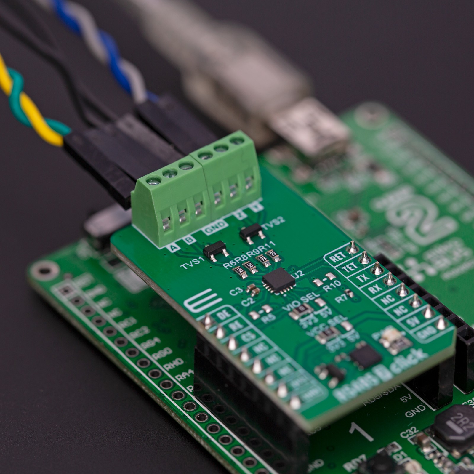
The THVD1424 RS-485 transceiver can be used in half-duplex or full-duplex RS-485 networks by populating an onboard R5 resistor. Full duplex mode is the default state of this board (with unpopulated R5 resistor), where Y and Z terminal pins are driver output pins, and A/B pins are receiver input pins. By populating the R5 resistor, Half duplex mode is activated where the driver and receiver share the same bus pins (Y/Z pins are both driver and receiver pins). The device state is then controlled via two mikroBUS™ pins labeled DE and RE (driver and receiver enable/disable), routed to the default positions of the AN and RST pins of the mikroBUS™ socket.
The THVD1424 can also be used in slow-speed or fast-speed RS485 networks by populating a slew rate control R10 resistor. By default, with the R10 resistor unpopulated, the maximum speed of operation for both driver and receiver is 20Mbps. By populating it, the maximum speed of operation for both driver and receiver is 500kbps, where the receiver path has an additional noise filtering feature enabled. The THVD1424 also has built-in protection features such as supply undervoltage, bus short-circuit, and thermal shutdown.
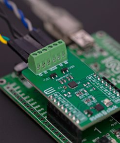
This Click board™ can operate with either 3.3V or 5V logic voltage levels selected via the VIO SEL jumper. This way, both 3.3V and 5V capable MCUs can use the communication lines properly. Also, the main power supply of the RS485 transceiver can be selected between 3.3V or 5V voltage levels selected via the VCC SEL jumper. The wide common-mode voltage range and low input leakage on bus pins make this Click board™ suitable for multi-point applications over long cable runs. However, the Click board™ comes equipped with a library containing easy-to-use functions and an example code that can be used, as a reference, for further development.
Specifications
Type
RS485
Applications
Can be used for industrial and multi-point applications over long cable runs
On-board modules
THVD1424 – full duplex RS485 transceiver from Texas Instruments
Key Features
Highly flexible, selectable power and logic voltage levels, configurable half and full duplex mode, pin-configurable 120Ω termination resistor on bus pins, configurable data rate, bus I/O protection, low power consumption, glitch-free power-up/power-down for hot plug-in capability, protection features, and more
Interface
GPIO,UART
Feature
ClickID
Compatibility
mikroBUS™
Click board size
M (42.9 x 25.4 mm)
Input Voltage
3.3V or 5V
Pinout diagram
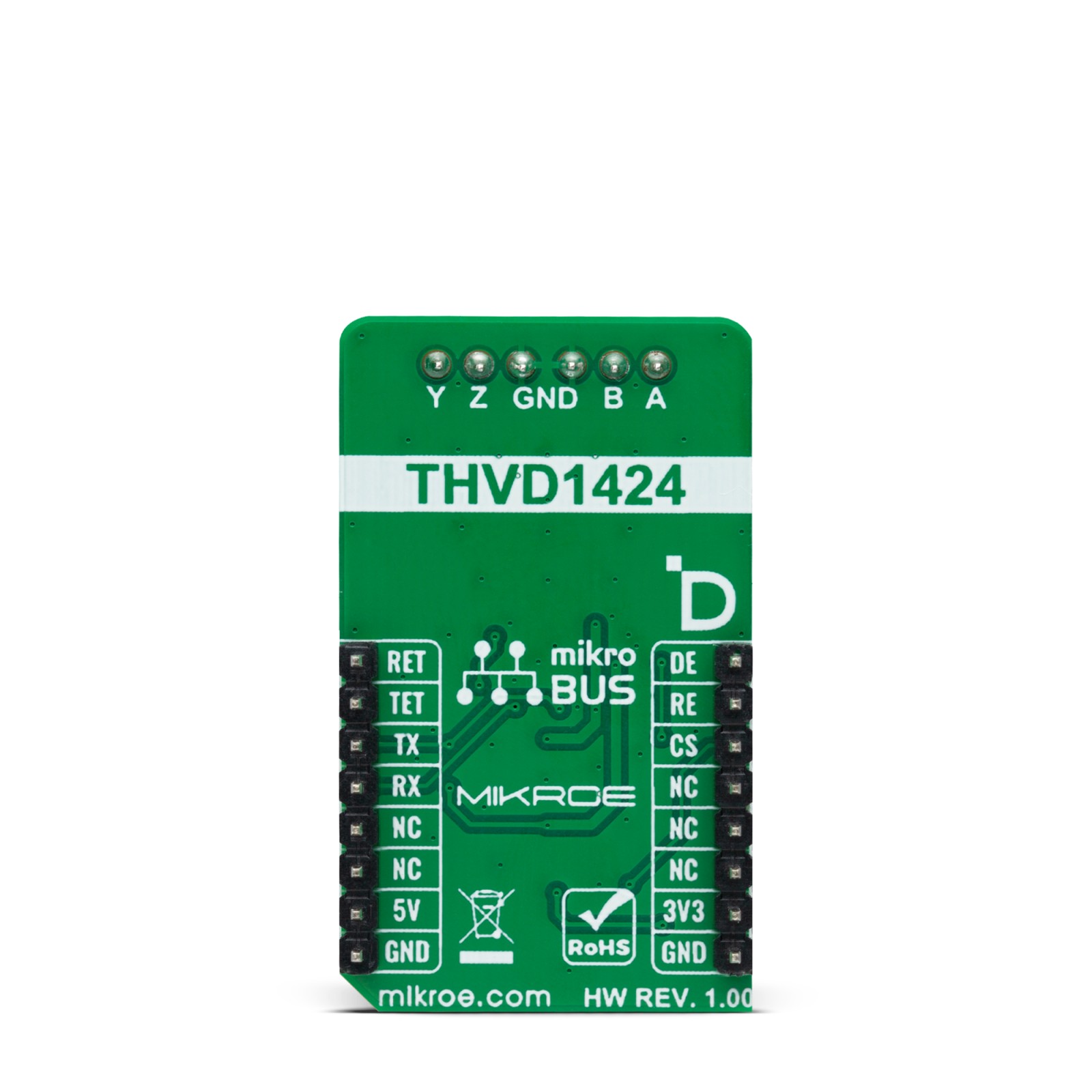
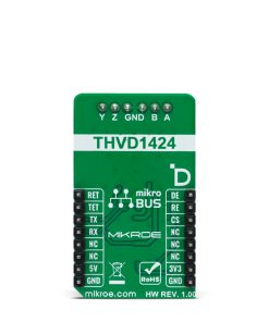
This table shows how the pinout on RS485 7 Click corresponds to the pinout on the mikroBUS™ socket (the latter shown in the two middle columns).
Onboard settings and indicators
Label | Name | Default | Description |
---|---|---|---|
LD1 | PWR | – | Power LED Indicator |
JP1 | VCC SEL | Left | Power Voltage Level Selection 3V3/5V: Left position 3V3, Right position 5V |
JP2 | VIO SEL | Left | Logic Voltage Level Selection 3V3/5V: Left position 3V3, Right position 5V |
R5 | R5 | Unpopulated | Half Duplex Mode Control Jumper |
R10 | R10 | Unpopulated | Slew Rate Control Jumper |
RS485 7 Click electrical specifications
Description | Min | Typ | Max | Unit |
---|---|---|---|---|
Supply Voltage | 3.3 | – | 5 | V |
Data Rate | 0.5 | – | 20 | Mbps |
ESD Protection | – | ±8 | – | kV |
Software Support
We provide a library for the RS485 7 Click as well as a demo application (example), developed using MIKROE compilers. The demo can run on all the main MIKROE development boards.
Package can be downloaded/installed directly from NECTO Studio Package Manager(recommended way), downloaded from our LibStock™ or found on Mikroe github account.
Library Description
This library contains API for RS485 7 Click driver.
Key functions
-
rs4857_receiver_enable
RS485 7 enables the receiver function. -
rs4857_driver_enable
RS485 7 enables the driver function.
Example Description
This example reads and processes data from RS485 7 clicks. The library also includes a function for enabling/disabling the receiver or driver and data writing or reading.
void application_task ( void )
{
if ( rs4857_generic_write( &rs4857, DEMO_MESSAGE, 10 ) )
{
rs4857_process( );
if ( app_buf_len > 0 )
{
log_printf( &logger, "%s", app_buf );
rs4857_clear_app_buf( );
}
}
Delay_ms( 2000 );
}
The full application code, and ready to use projects can be installed directly from NECTO Studio Package Manager(recommended way), downloaded from our LibStock™ or found on Mikroe github account.
Other Mikroe Libraries used in the example:
- MikroSDK.Board
- MikroSDK.Log
- Click.RS4857
Additional notes and informations
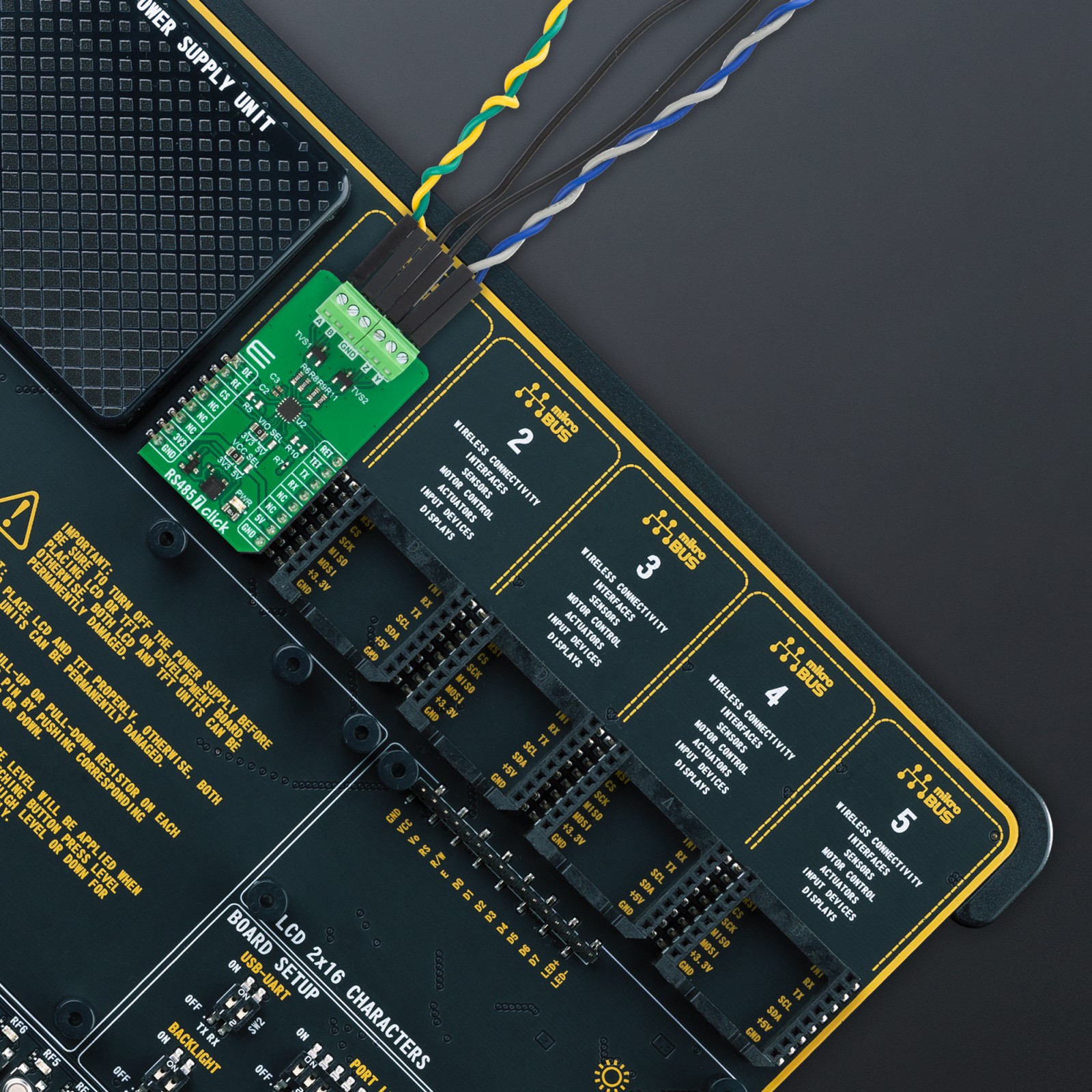
Depending on the development board you are using, you may need USB UART click, USB UART 2 Click or RS232 Click to connect to your PC, for development systems with no UART to USB interface available on the board. UART terminal is available in all MIKROE compilers.
mikroSDK
This Click board™ is supported with mikroSDK – Mikroe Software Development Kit, that needs to be downloaded from the LibStock and installed for the compiler you are using to ensure proper operation of mikroSDK compliant Click board™ demo applications.
For more information about mikroSDK, visit the official page.