How does it work?
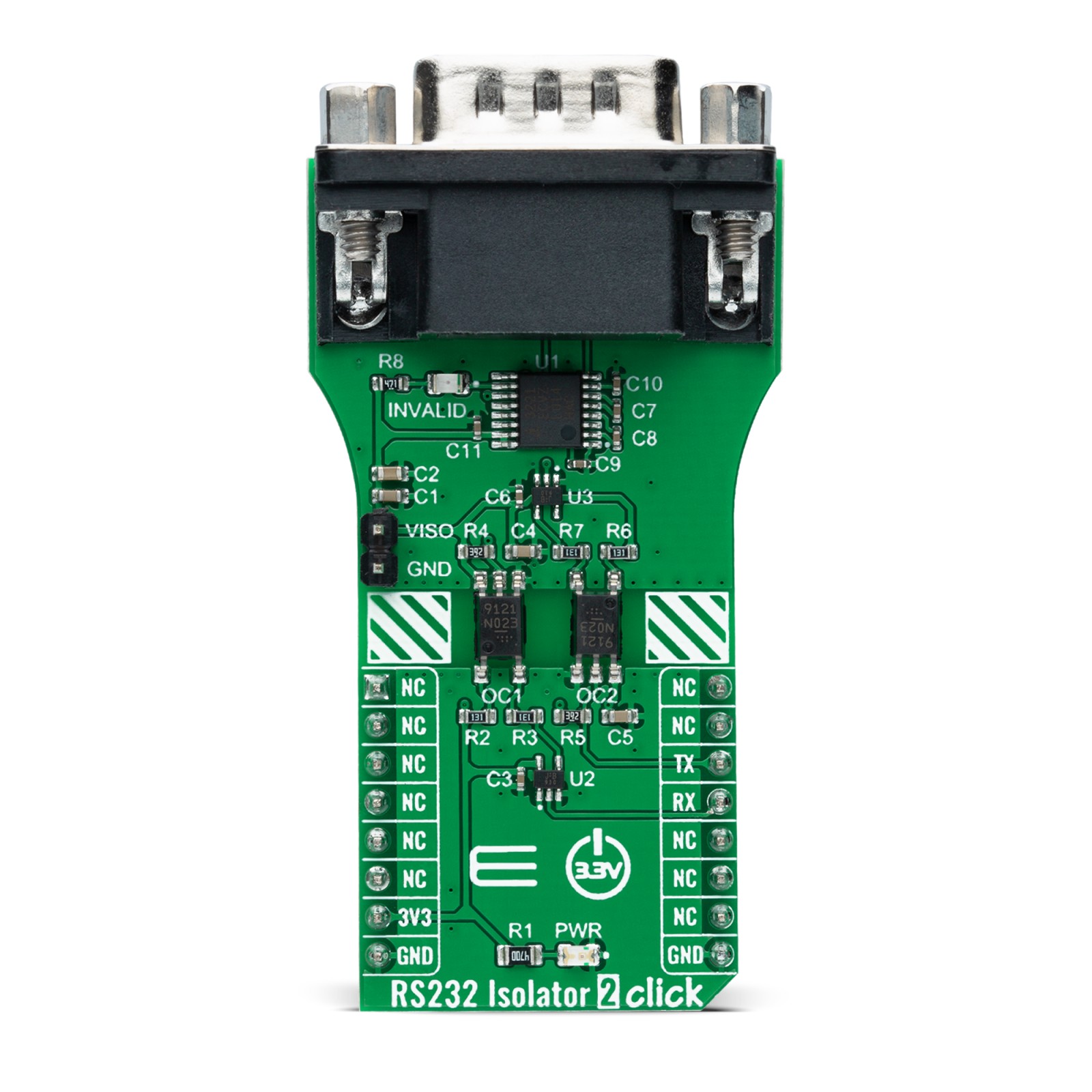
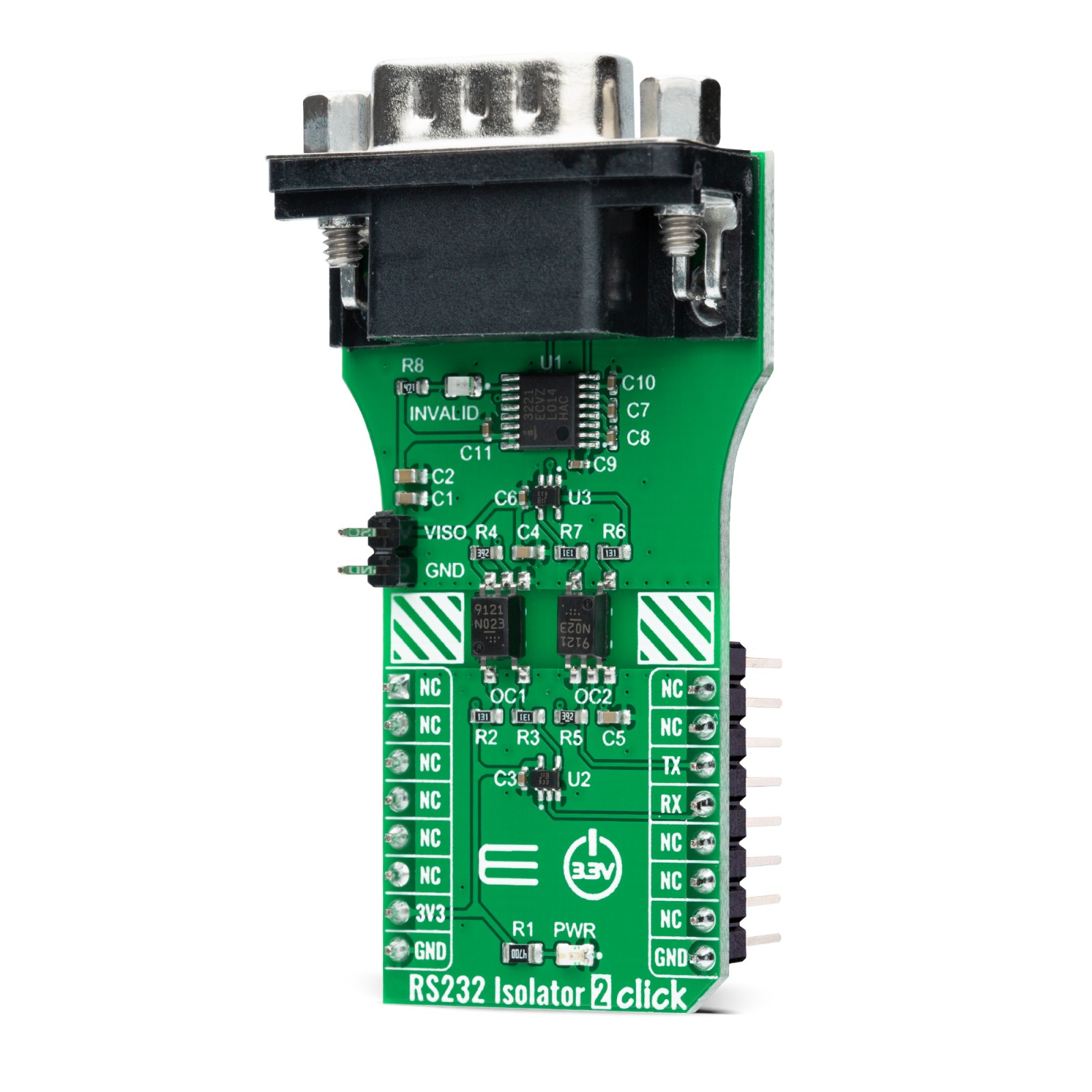
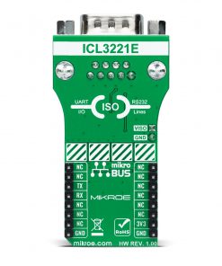
RS232 Isolator 2 Click as its foundation uses the ICL3221, a 3.3V powered RS232 transmitter/receiver that provides ±15kV ESD protection on its RS232 pins from Renesas. It features an automatic power-down function that occurs when the RS232 cable is removed and conserves system power automatically and power-up again when a valid RS232 voltage is applied to any receiver input. It also ensures data rates greater than 250kbps even at worst-case load conditions.
This Click board™ represents an isolated RS232 interface configuration using PS9121, an optically coupled high-speed active low type isolator from Renesas, containing a GaAlAs LED on the input side, a photodiode, and a signal processing circuit on the output side rated for 3.75kV isolation and up to 15Mbps data rate. The RS232 transceiver ICL3221 is specified with a data rate of 250kbps and operates from a 3.0V to 3.6V external power supply header on the board’s right side. In addition to the optocouplers, the TC7SZ125FU logic buffers from Toshiba Semiconductor are used to drive the necessary LED currents that usually cannot be provided by low-power MCUs or RS232 receiver outputs.
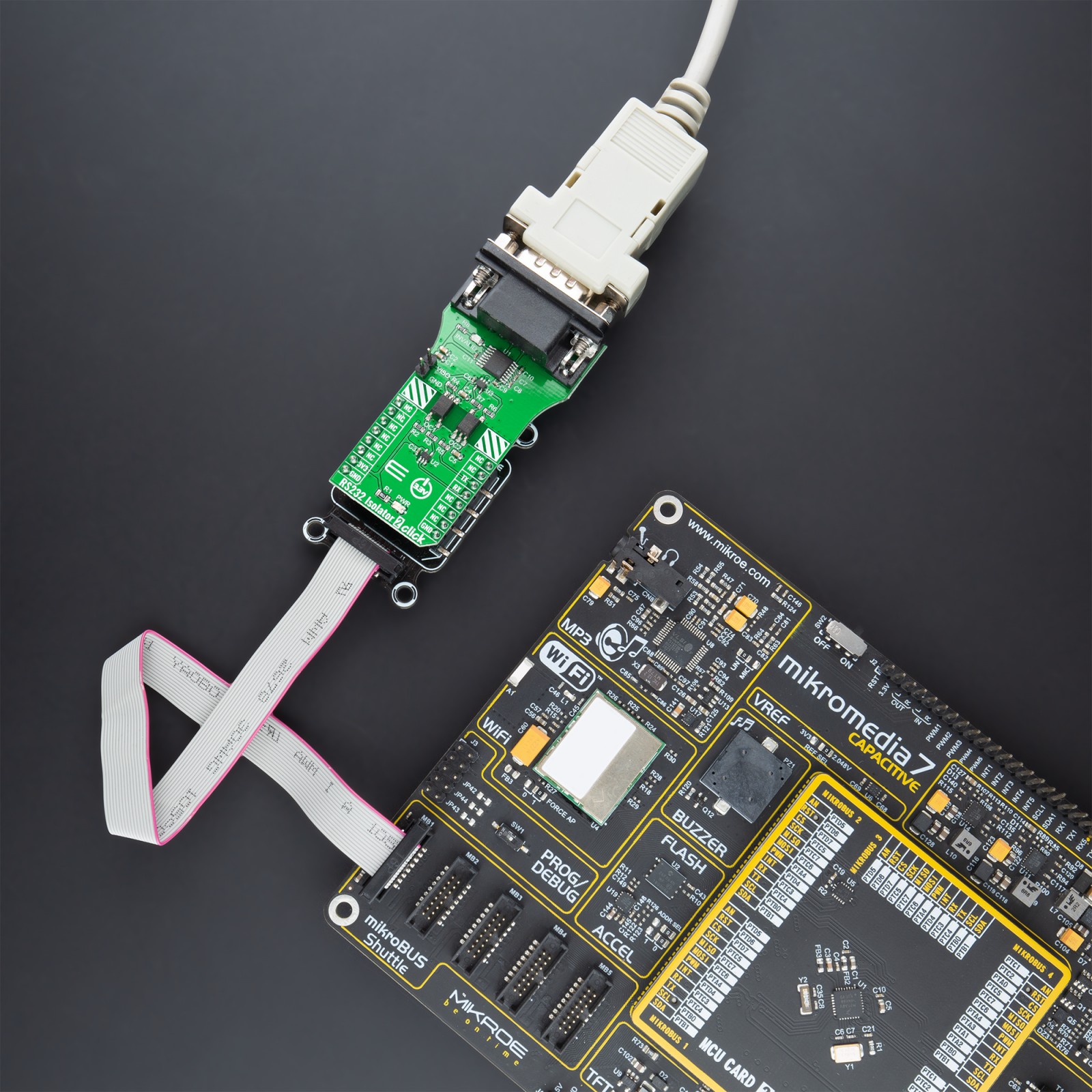
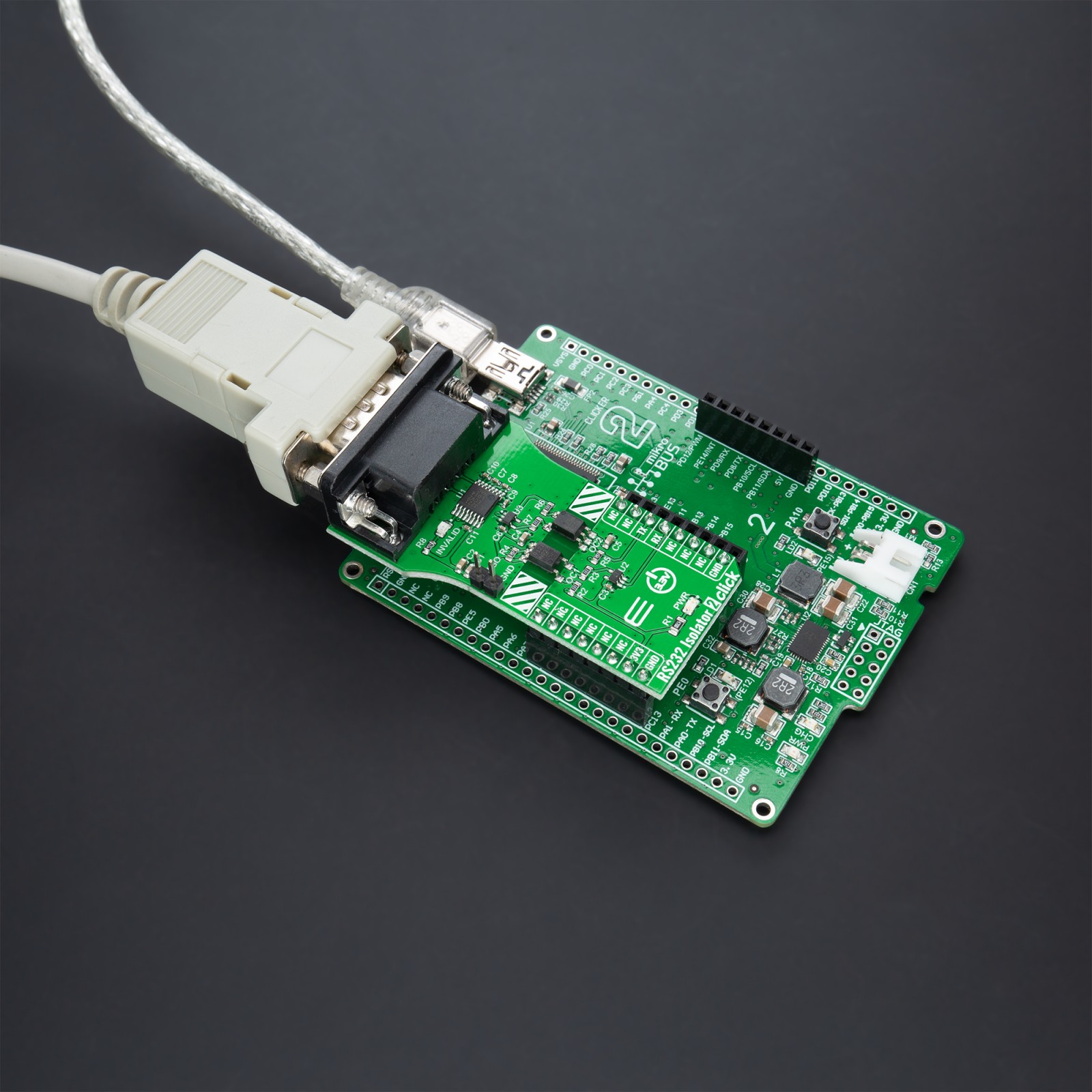
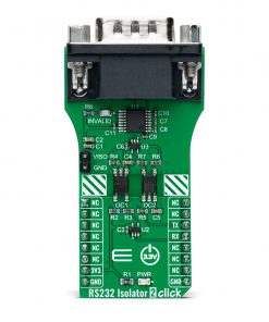
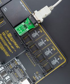
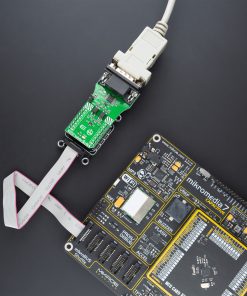
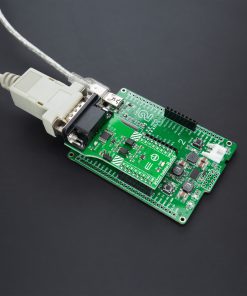
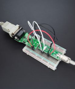
The ICL3221 communicates with MCU using the UART interface with the default baud rate of 115200bps for the data transfer. It also comes equipped with the standard DB-9 connector, which makes interfacing with the RS232 simple and easy, and a red diode indicator labeled as INVALID indicates whether a valid RS232 signal is present not.
This diode always indicates whether a valid RS232 signal is present at any of the receiver inputs, giving the user a way to determine when the interface block should power down. If the interface cable is disconnected from the DB-9 connector and all the receiver inputs are floating, the ICL3221 detects invalid levels turning the LED. Reconnecting the cable restores valid levels at the receiver inputs, the diode turns off, and the power management logic wakes up the interface block.
This Click board™ can be operated only with a 3.3V logic voltage level. The board must perform appropriate logic voltage level conversion before use with MCUs with different logic levels. However, the Click board™ comes equipped with a library containing functions and an example code that can be used, as a reference, for further development.
Specifications
Type
Isolators,RS232
Applications
Can be used for isolation of RS-232 signals, portable equipment, and where the low operational power consumption and even lower standby power consumption are critical.
On-board modules
ICL3221 – RS-232 transmitter/receiver that provide ±15kV ESD protection on its RS-232 pins from Renesas
PS9121 – optically coupled high-speed active low type isolator from Renesas
Key Features
Low power consumption, automatic power-down, assured minimum data rate of 250kbps, an isolated RS-232 interface using Renesas digital high-speed optocouplers, and more.
Interface
UART
Feature
No ClickID
Compatibility
mikroBUS™
Click board size
L (57.15 x 25.4 mm)
Input Voltage
3.3V
Pinout diagram
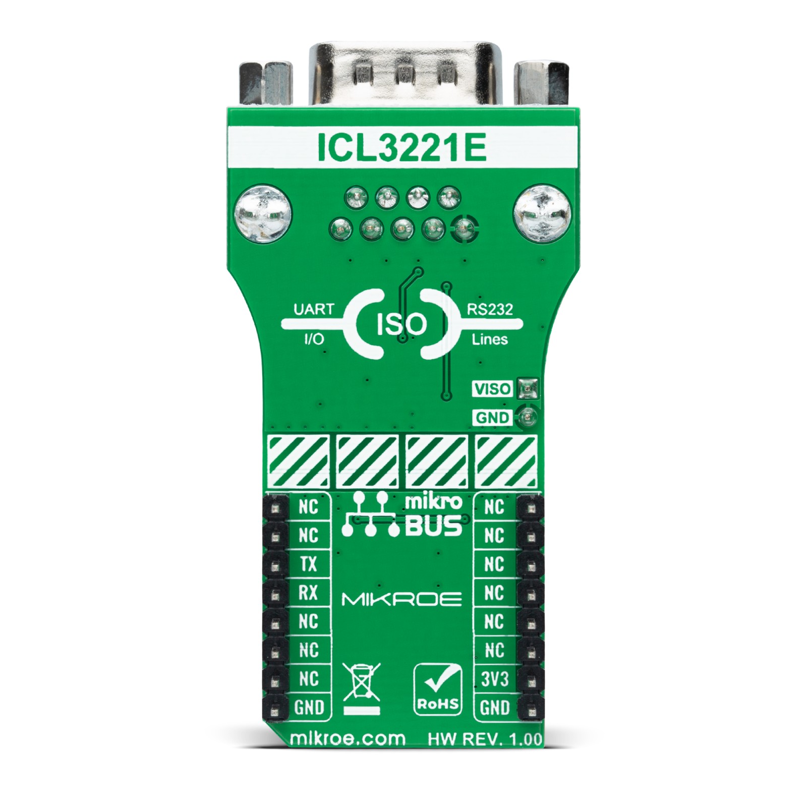
This table shows how the pinout on RS232 Isolator 2 Click corresponds to the pinout on the mikroBUS™ socket (the latter shown in the two middle columns).
Onboard settings and indicators
Label | Name | Default | Description |
---|---|---|---|
LD1 | PWR | – | Power LED Indicator |
LD2 | INVALID | – | Invalid RS232 Level LED Indicator |
J1 | VISO | Populated | External Power Supply Header |
RS232 Isolator 2 Click electrical specifications
Description | Min | Typ | Max | Unit |
---|---|---|---|---|
Supply Voltage | – | 3.3 | – | V |
External Supply Voltage VISO | 3 | 3.3 | 3.6 | V |
Isolation Voltage Range | – | – | 3.75 | kV |
Data Rate | – | – | 15 | Mbps |
Operating Temperature Range | -40 | +25 | +85 | °C |
Software Support
We provide a library for the RS232 Isolator 2 Click as well as a demo application (example), developed using MikroElektronika compilers. The demo can run on all the main MikroElektronika development boards.
Package can be downloaded/installed directly from NECTO Studio Package Manager(recommended way), downloaded from our LibStock™ or found on mikroE github account.
Library Description
This library contains API for RS232 Isolator 2 Click driver.
Key functions:
rs232isolator2_cfg_setup
– Config Object Initialization function.rs232isolator2_init
– Initialization function.rs232isolator2_default_cfg
– Click Default Configuration function.
Examples description
This library contains API for RS232 Isolator 2 Click driver. This example transmits/receives and processes data from RS232 Isolator 2 clicks. The library initializes and defines the UART bus drivers to transmit or receive data.
The demo application is composed of two sections :
void application_task ( void ) { #ifdef TRANSIVER rs232isolator2_send_data( &rs232isolator2, demo_message ); log_printf( &logger, "%s", demo_message ); Delay_ms( 2000 ); log_printf( &logger, "------------------rn" ); #endif #ifdef RECIEVER rs232isolator2_process( ); if ( app_buf_len > 0 ) { log_printf( &logger, "%s", app_buf ); rs232isolator2_clear_app_buf( ); } #endif }
The full application code, and ready to use projects can be installed directly from NECTO Studio Package Manager(recommended way), downloaded from our LibStock™ or found on mikroE github account.
Other mikroE Libraries used in the example:
- MikroSDK.Board
- MikroSDK.Log
- Click.Rs232Isolator2
Additional notes and informations
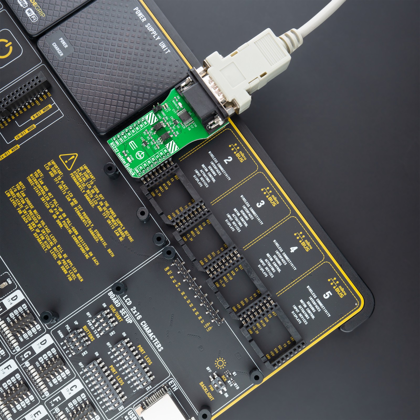
Depending on the development board you are using, you may need USB UART click, USB UART 2 click or RS232 click to connect to your PC, for development systems with no UART to USB interface available on the board. The terminal available in all MikroElektronika compilers, or any other terminal application of your choice, can be used to read the message.
mikroSDK
This Click board™ is supported with mikroSDK – MikroElektronika Software Development Kit. To ensure proper operation of mikroSDK compliant Click board™ demo applications, mikroSDK should be downloaded from the LibStock and installed for the compiler you are using.
For more information about mikroSDK, visit the official page.