How does it work?
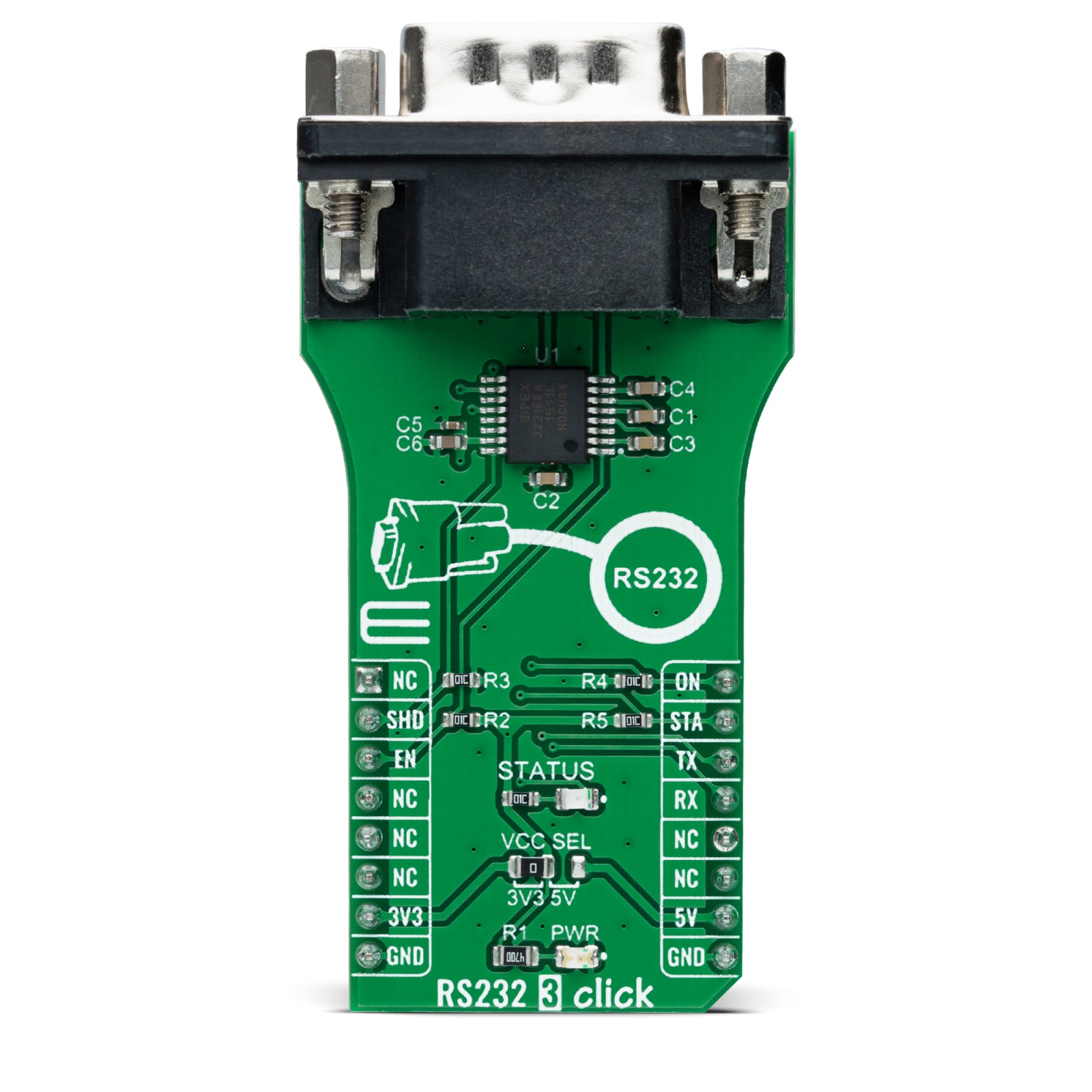
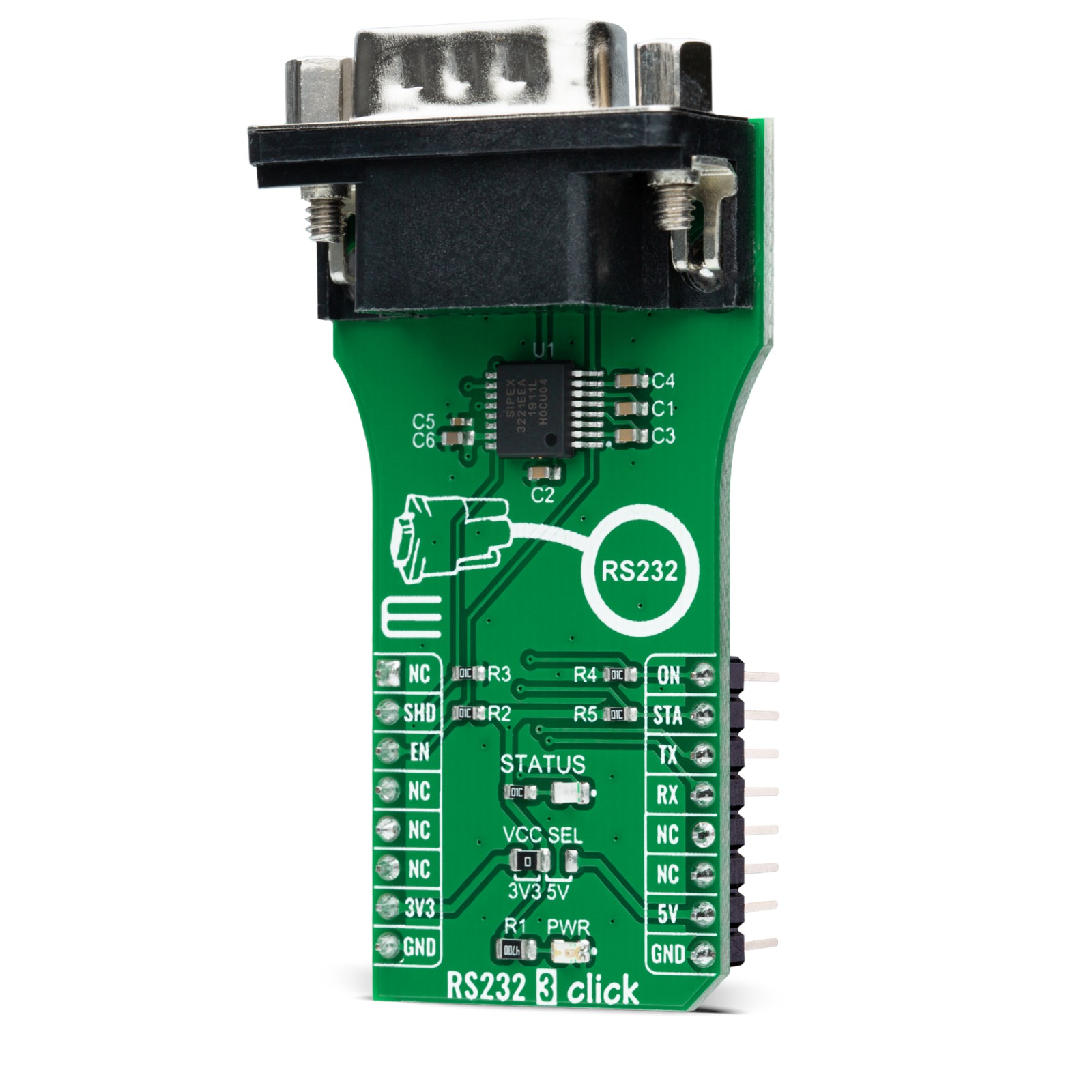
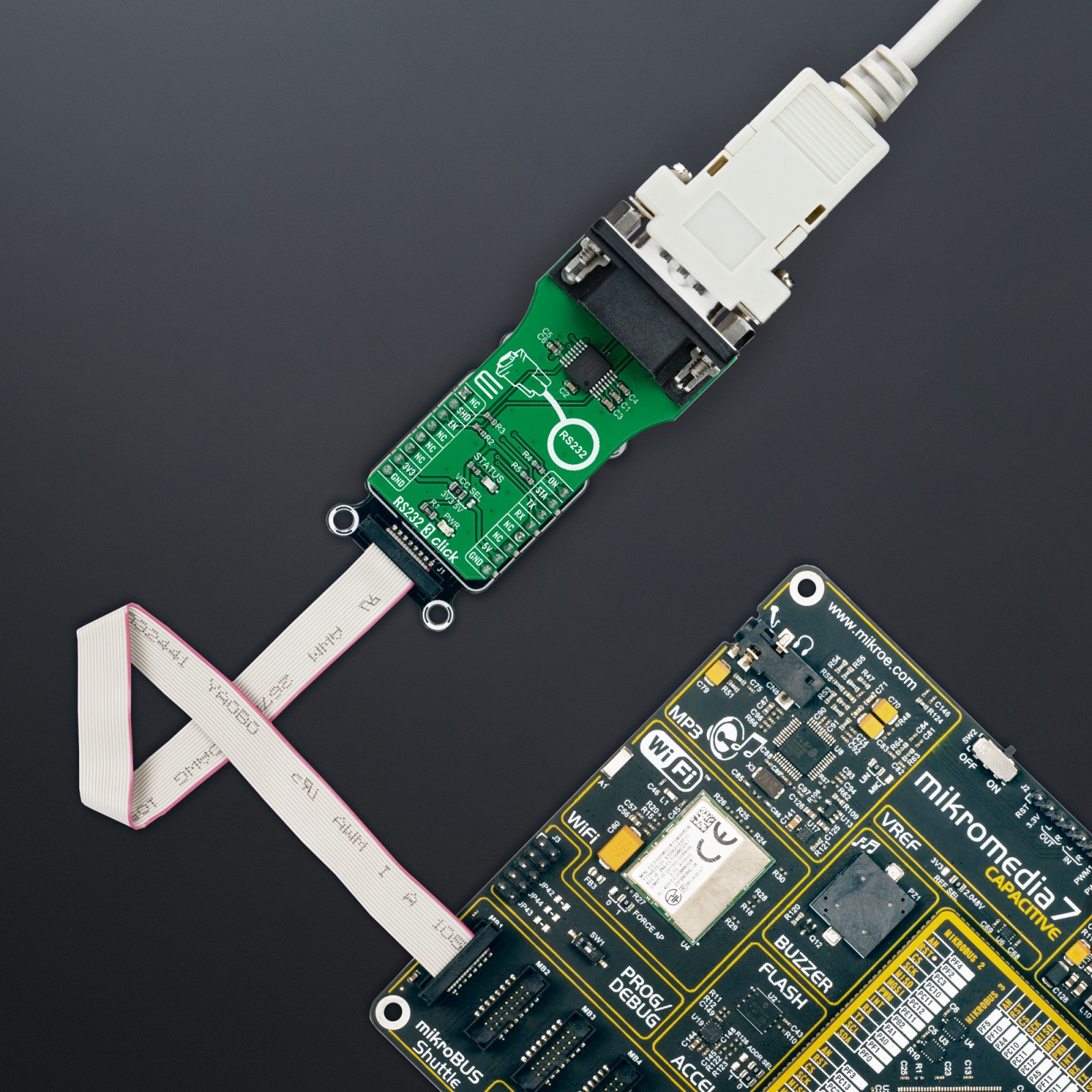
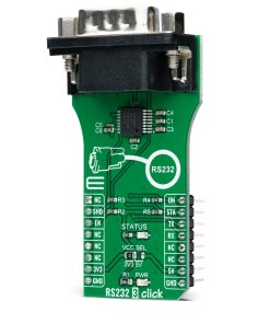
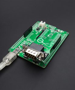
RS232 3 Click as its foundation uses the SP3221E, a low power, RS232 transceiver (single driver/single receiver) solution with a 250kbps data rate from MaxLinear. The SP3221E uses an internal high-efficiency, charge-pump power supply and is compliant with EIA/TIA-232-F standards when powered by any of the mikroBUS™ power rails. This charge pump and MaxLinear’s driver architecture allow the SP3221E to deliver compliant RS-232 performance from a single power supply intended for portable or handheld applications such as embedded computers, data logging devices, medical diagnostics, and remote sensors.
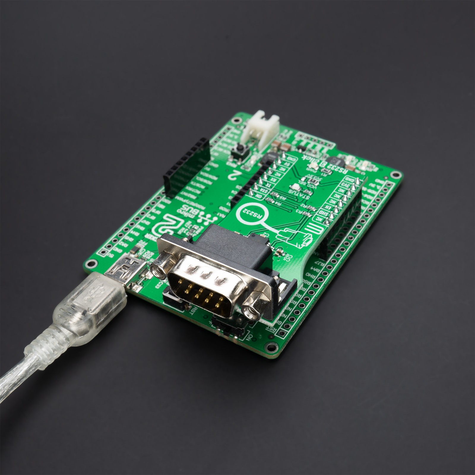
The SP3221E communicates with MCU using the UART interface with the default baud rate of 115200bps for the data transfer. It also comes equipped with the standard DB-9 connector, which makes interfacing with the RS232 simple and easy, and a red LED indicator labeled as STATUS that indicates whether a valid RS232 signal is present not. This signal is also routed to the INT pin of the mikroBUS™ socket, labeled as STA. Alongside UART communication, several signals connected to the mikroBUS™ socket pins are also used to forward the information to the MCU.
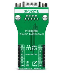
For proper operation of SP3221E, this board uses a combination of two pins, EN and SHD pins routed to the CS and RST pins of the mikroBUS™ socket. The receiver is active when the AUTO ON-LINE® circuitry is enabled or when in Shutdown. The AUTO ON-LINE® feature, controlled via ON pin routed to the PWM pin of the mikroBUS™ socket, allows the SP3221E to automatically “Wake-Up” from a Shutdown state when an RS232 cable is connected, and a peripheral device is turned on. During the Shutdown, the receiver will continue to be active. If there is no activity at the receiver for a more extended period or when the SHD pin is enabled, the device goes into a Standby mode. Also, driving the EN pin to a high state forces the receiver’s output into a high impedance state.
This Click board™ can operate with both 3.3V and 5V logic voltage levels selected via the VCC SEL jumper. This way, it is allowed for both 3.3V and 5V capable MCUs to use the communication lines properly. However, the Click board™ comes equipped with a library that contains easy-to-use functions and an example code that can be used, as a reference, for further development.
Specifications
Type
RS232
Applications
Can be used for low-power serial communications, portable serial devices, point-of-sale equipment, and many more applications
On-board modules
SP3221E – low-power RS232 transceiver from MaxLinear
Key Features
EIA/TIA-232-F standards, AUTO ON-LINE® circuitry automatically
wakes up from a shutdown, minimum 250kbps data rate under load, Regulated charge pump yields stable RS-232 outputs regardless of power supply, and more
Interface
UART
Feature
No ClickID
Compatibility
mikroBUS™
Click board size
L (57.15 x 25.4 mm)
Input Voltage
3.3V or 5V
Pinout diagram
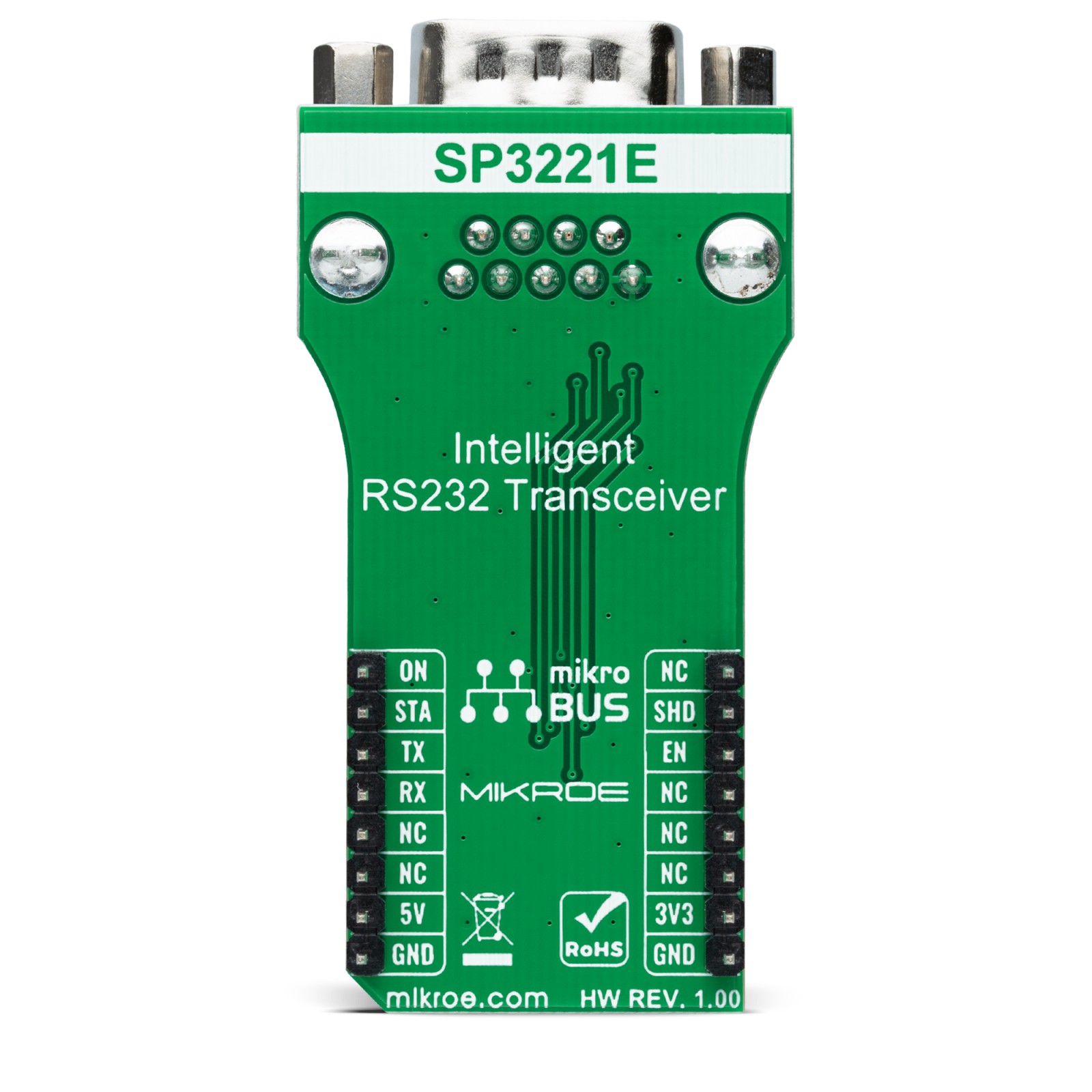
This table shows how the pinout on RS232 3 Click corresponds to the pinout on the mikroBUS™ socket (the latter shown in the two middle columns).
Onboard settings and indicators
Label | Name | Default | Description |
---|---|---|---|
LD1 | PWR | – | Power LED Indicator |
LD2 | STATUS | – | Valid RS232 Signal LED Indicator |
JP1 | VCC SEL | Left | Logic Level Voltage Selection 3V3/5V: Left position 3V3, Right position 5V |
RS232 3 Click electrical specifications
Description | Min | Typ | Max | Unit |
---|---|---|---|---|
Supply Voltage | 3.3 | – | 5 | V |
Data Rate | 250 | – | – | kbps |
Operating Temperature Range | -40 | +25 | +85 | °C |
Software Support
We provide a library for the RS232 3 Click as well as a demo application (example), developed using MikroElektronika compilers. The demo can run on all the main MikroElektronika development boards.
Package can be downloaded/installed directly from NECTO Studio Package Manager(recommended way), downloaded from our LibStock™ or found on Mikroe github account.
Library Description
This library contains API for RS232 3 Click driver.
Key functions
-
rs2323_generic_write
This function writes a desired number of data bytes by using UART serial interface. -
rs2323_generic_read
This function reads a desired number of data bytes by using UART serial interface.
Example Description
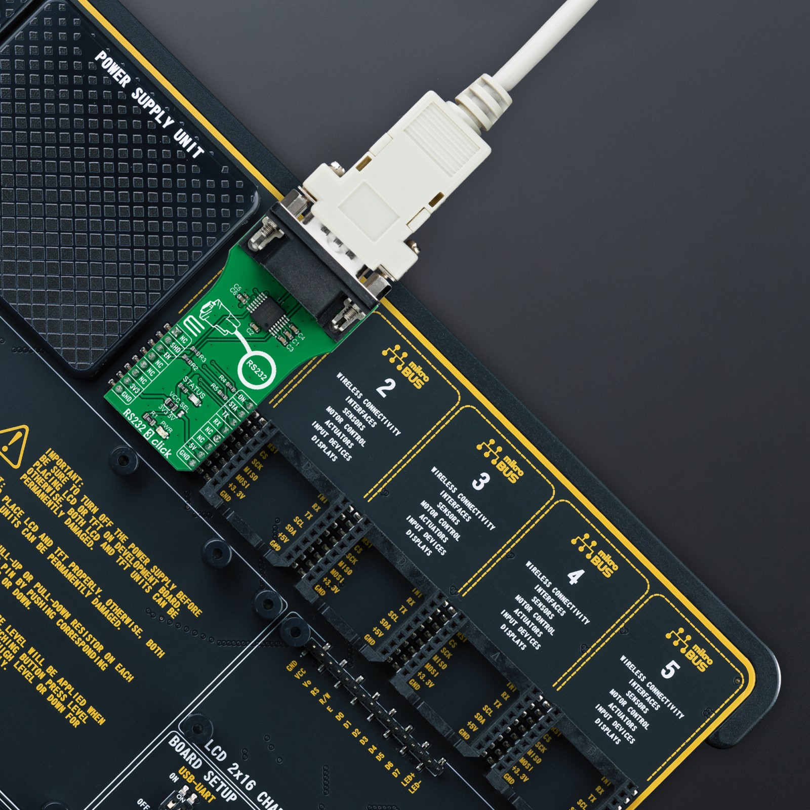
This example demonstrates the use of an RS232 3 Click board™ by showing the communication between the two click board configured as a receiver and transmitter.
void application_task ( void )
{
#ifdef DEMO_APP_TRANSMITTER
rs2323_generic_write( &rs2323, DEMO_TEXT_MESSAGE, strlen( DEMO_TEXT_MESSAGE ) );
log_printf( &logger, "%s", ( char * ) DEMO_TEXT_MESSAGE );
Delay_ms( 3000 );
#else
uint8_t rx_data;
if ( rs2323_generic_read( &rs2323, &rx_data, 1 ) > 0 )
{
log_printf( &logger, "%c", rx_data );
}
#endif
}
The full application code, and ready to use projects can be installed directly from NECTO Studio Package Manager(recommended way), downloaded from our LibStock™ or found on Mikroe github account.
Other Mikroe Libraries used in the example:
- MikroSDK.Board
- MikroSDK.Log
- Click.RS2323
Additional notes and informations
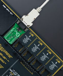
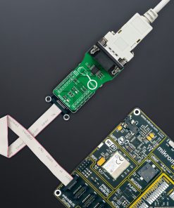
Depending on the development board you are using, you may need USB UART click, USB UART 2 Click or RS232 Click to connect to your PC, for development systems with no UART to USB interface available on the board. UART terminal is available in all MikroElektronika compilers.
mikroSDK
This Click board™ is supported with mikroSDK – MikroElektronika Software Development Kit. To ensure proper operation of mikroSDK compliant Click board™ demo applications, mikroSDK should be downloaded from the LibStock and installed for the compiler you are using.
For more information about mikroSDK, visit the official page.