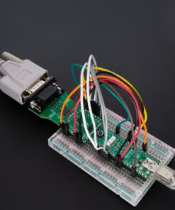
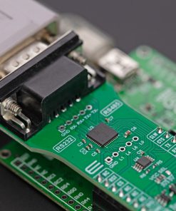
How does it work?
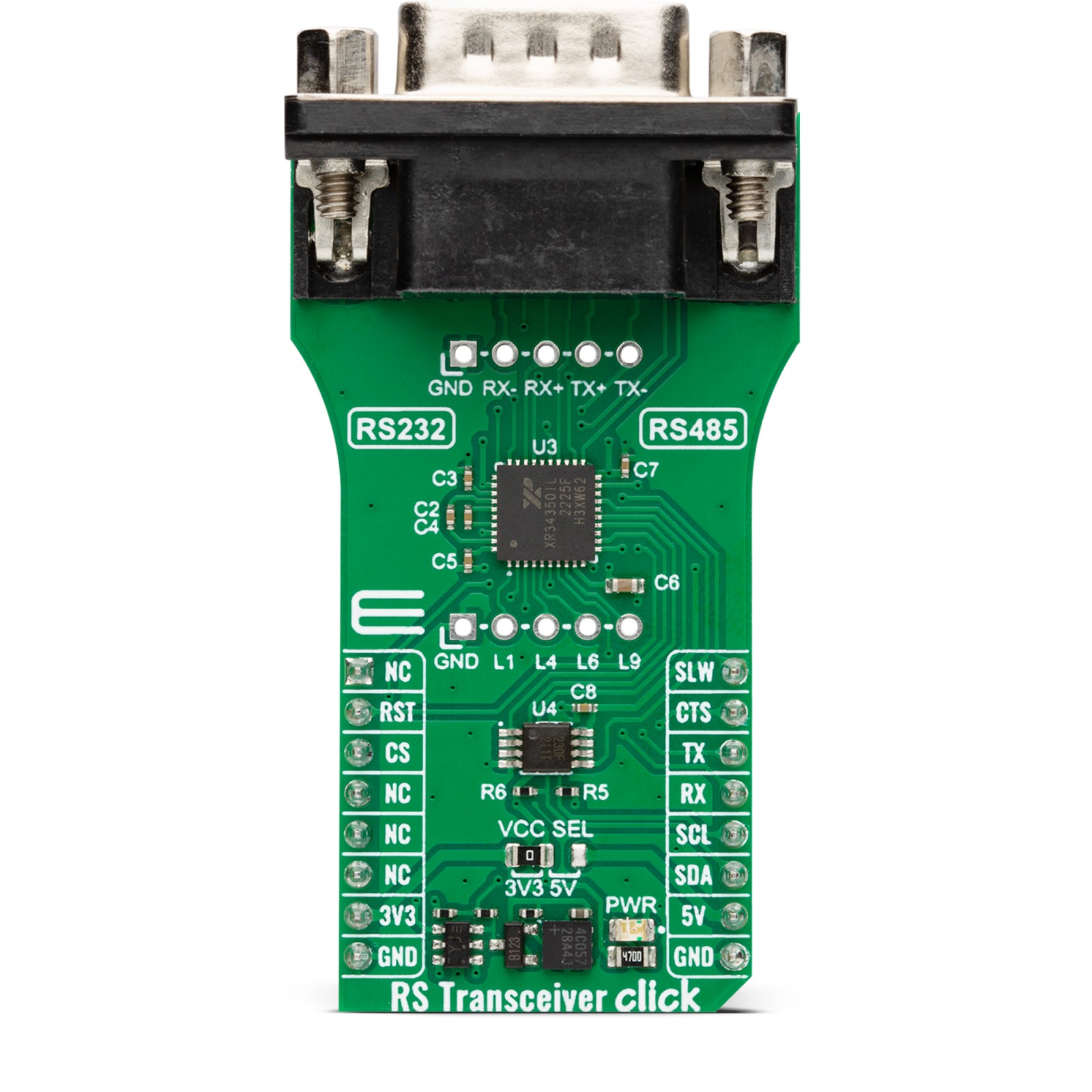
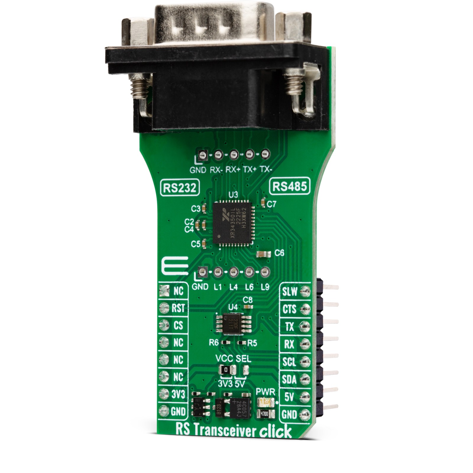
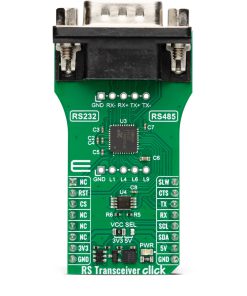
RS Transceiver Click is based on the XR34350, an RS-232/RS-422/RS-485 serial transceiver with internal termination and wide output swing from MaxLinear. It is an advanced multiprotocol transceiver with dual protocol serial ports, RS-232 or RS-485/RS-422. The RS-485/RS-422 modes feature one driver and one receiver (1TX/1RX) in both half and full duplex configurations, where high-speed drivers operate up to 20Mbps. The RS-485 and RS-422 are both 2-Wire protocols, where the RS-485 can have multiple commanding devices and listeners. On the other hand, the RS-422 can have only one commander and multiple listeners.
The RS-232 mode features three drivers and five receivers (3TX/5RX) and provides full support for all eight signals. In the RS-232 mode, it can achieve data rates up to 1Mbps. All transceiver drivers can be slew limited to 250Kbps in any mode, thus minimizing electromagnetic interference. The XR34350 eliminates the need to design a termination resistor when sharing a single connector or a pair of lines across multiple serial protocols. It integrates the terminal resistor and switching control, thus allowing it to be switched in and out of the circuit with a single pin. The RS-485/RS-422 receiver inputs are high impedance, while the RS-232 receiver input is pulled-down, allowing up to 256 devices on a single communication bus.
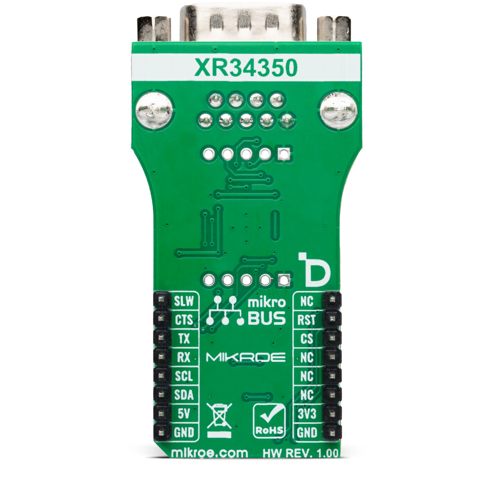
The RS Transceiver uses a standard UART interface to communicate with the host MCU, with commonly used UART RX and TX. In addition, the UART flow control pins CTS and RTS are available on the mikroBUS™ socket. The transceiver can be reset over the RST pin, and limiting can be activated over the SLW pin.
As the mikroBUS™ socket is pin-limited, the RS Transceiver includes the TCA9536, a remote 4-bit IO expander with configuration registers from Texas Instruments, bringing an additional four I/Os to the host MCU. The TCA9536 communicates with the host MCU over the standard I2C serial interface supporting fast mode up to 1MHz. Using this I/O expander, you can set half-duplex or full-duplex mode over the DIR1 pin of the transceiver. There are two mode pins, MODE0 and MODE1, that you can use to select one mode between Loopback Mode, Half-Duplex RS-485 Mode #1, RS-232 Mode, and Full-Duplex RS-485/422 Mode #1. The Term pin only applies in the half-duplex and full-duplex RS-485/RS-422 modes as it enables the internal termination resistor.
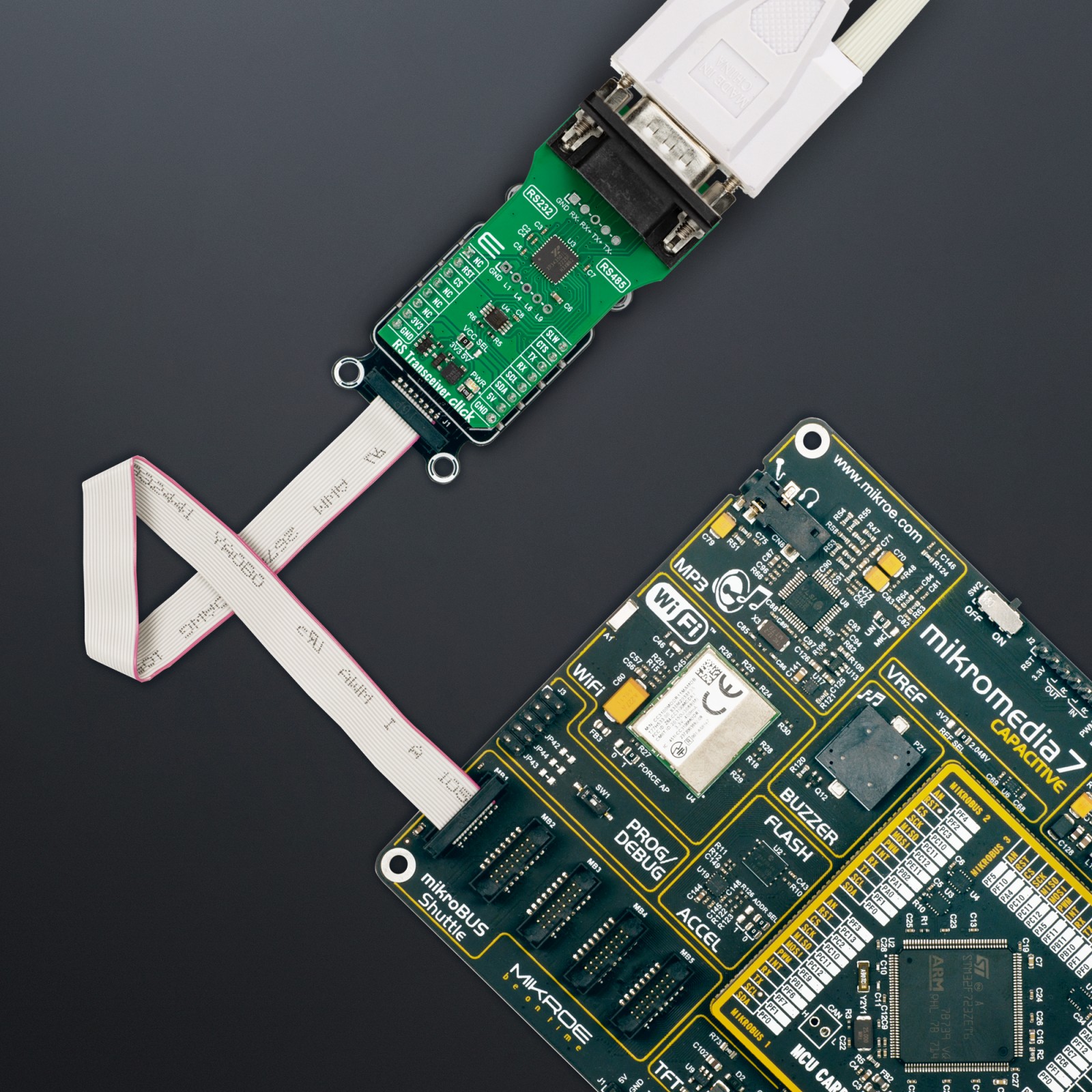
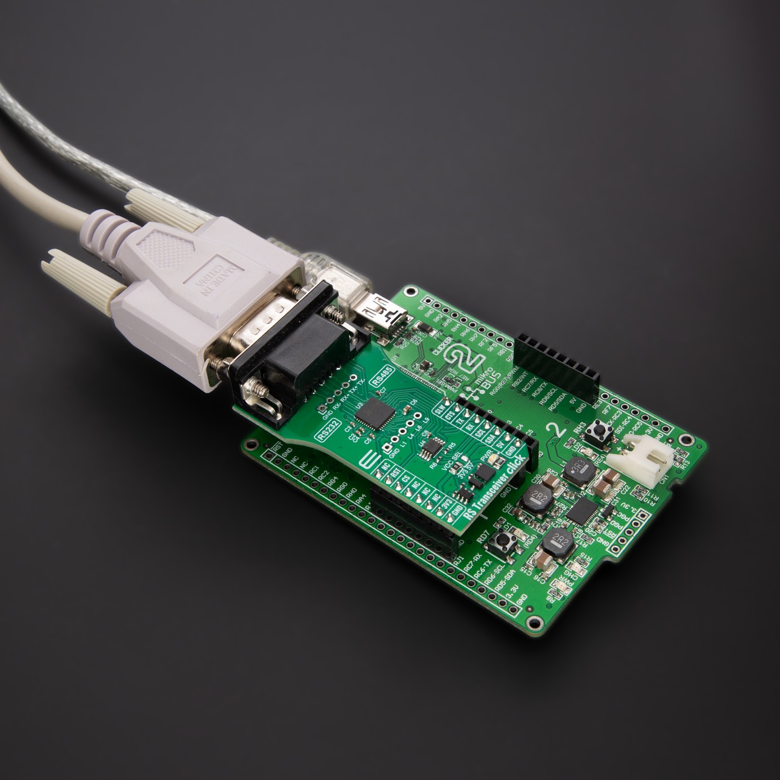
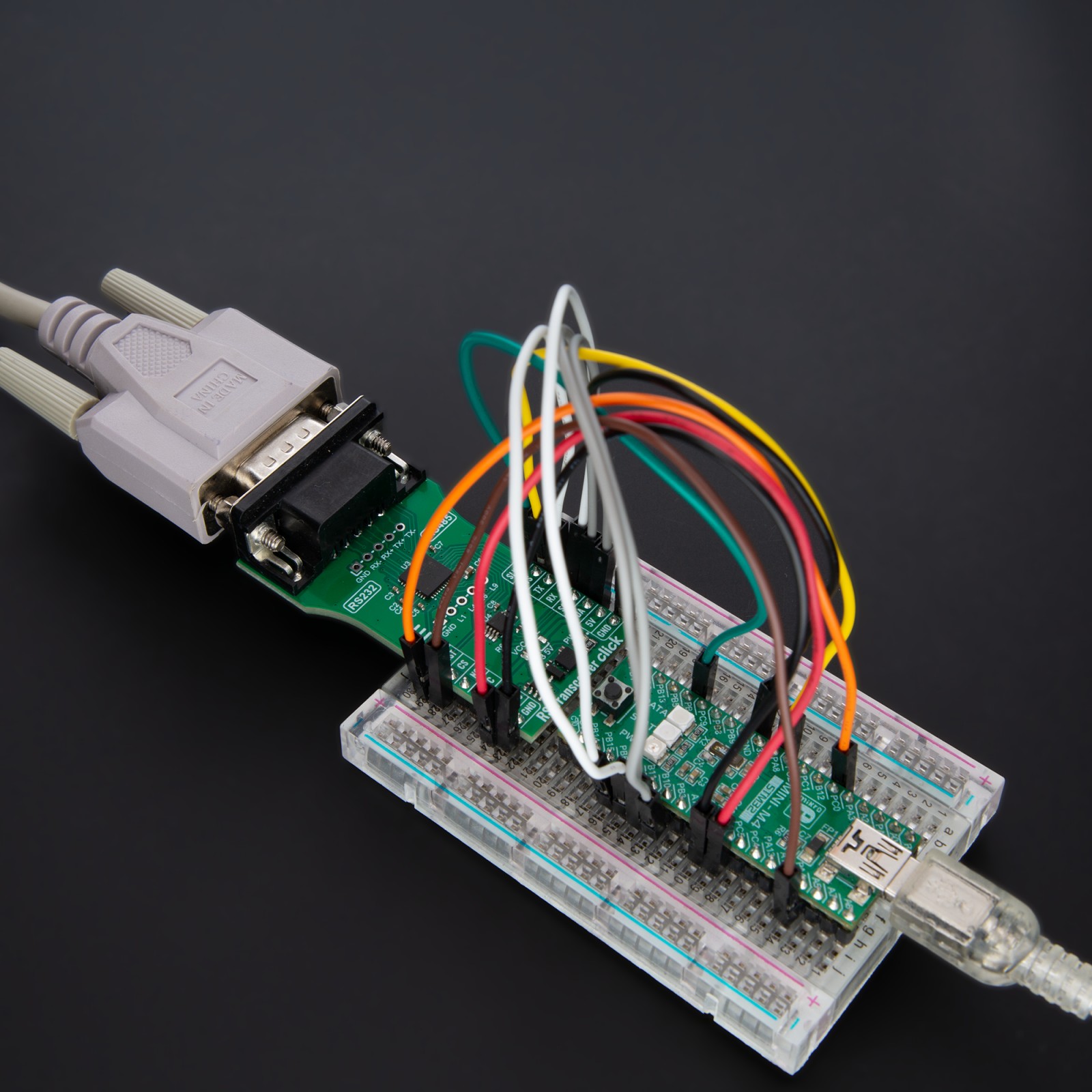
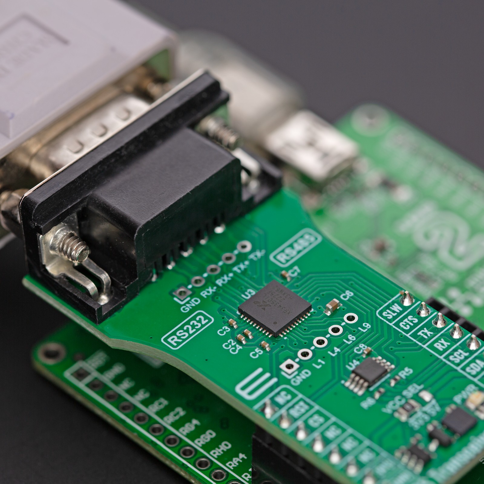
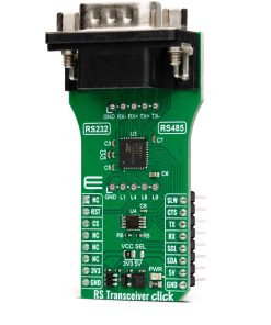
There are two additional headers on this Click board™. The lower one brings GND, L1, L4, L6, and L9 pins from the transceiver, and the RS-485 signals are also available on the upper header for testing purposes of the full and half duplex modes. These signals are also available on the DE-9 connector.
This Click board™ can operate with either 3.3V or 5V logic voltage levels selected via the VCC SEL jumper. This way, both 3.3V and 5V capable MCUs can use the communication lines properly. However, the Click board™ comes equipped with a library containing easy-to-use functions and an example code that can be used, as a reference, for further development.
Specifications
Type
RS232,RS485
Applications
Can be used for the development of low-power serial communications, portable serial devices, point-of-sale equipment, HVAC systems, building automation, and more
On-board modules
XR34350 – RS-232/RS-422/RS-485 serial transceiver with internal termination and wide output swing from MaxLinear
Key Features
Dual protocol serial ports RS232 or RS485/RS422, RS485/RS422 signaling rate up to 20Mbps, RS232 up to 1Mbps, up to 256 nodes, slew limiting to 250Kbps, high swing driver outputs, half/full duplex, loopback mode, internal termination resistor, robust ESD protection, and more
Interface
I2C,UART
Feature
ClickID
Compatibility
mikroBUS™
Click board size
L (57.15 x 25.4 mm)
Input Voltage
3.3V or 5V
Pinout diagram
This table shows how the pinout on RS Transceiver Click corresponds to the pinout on the mikroBUS™ socket (the latter shown in the two middle columns).
Onboard settings and indicators
Label | Name | Default | Description |
---|---|---|---|
LD1 | PWR | – | Power LED Indicator |
JP1 | VCC SEL | Left | Power/Logic Level Voltage Selection 3V3/5V: Left position 3V3, Right position 5V |
RS Transceiver Click electrical specifications
Description | Min | Typ | Max | Unit |
---|---|---|---|---|
Supply Voltage | 3.3 | – | 5 | V |
RS485/RS422 Data Rate | – | 20 | Kbps | |
RS232 Data Rate | – | – | 4 | Mbps |
ESD Protection (HBM) | – | – | ±15 | kV |
Software Support
We provide a library for the RS Transceiver Click as well as a demo application (example), developed using MIKROE compilers. The demo can run on all the main MIKROE development boards.
Package can be downloaded/installed directly from NECTO Studio Package Manager (recommended), downloaded from our LibStock™ or found on Mikroe github account.
Library Description
This library contains API for RS Transceiver Click driver.
Key functions
-
rstransceiver_set_op_mode
RS Transceiver sets the operating mode function. -
rstransceiver_mode_full_duplex
RS Transceiver sets the Full-Duplex mode function. -
rstransceiver_device_enable
RS Transceiver enables the device function.
Example Description
This example reads and processes data from RS Transceiver Click board™. The library also includes a function for selecting the desired operating mode, enabling/disabling the receiver or driver and data writing or reading.
void application_task ( void )
{
if ( rstransceiver_generic_write( &rstransceiver, DEMO_MESSAGE, strlen( DEMO_MESSAGE ) ) )
{
if ( rstransceiver_generic_read( &rstransceiver, app_buf, strlen( DEMO_MESSAGE ) ) )
{
log_printf( &logger, "%s", app_buf );
memset( app_buf, 0, PROCESS_BUFFER_SIZE );
Delay_ms( 2000 );
}
}
}
The full application code, and ready to use projects can be installed directly from NECTO Studio Package Manager (recommended), downloaded from our LibStock™ or found on Mikroe github account.
Other Mikroe Libraries used in the example:
- MikroSDK.Board
- MikroSDK.Log
- Click.RSTransceiver
Additional notes and informations
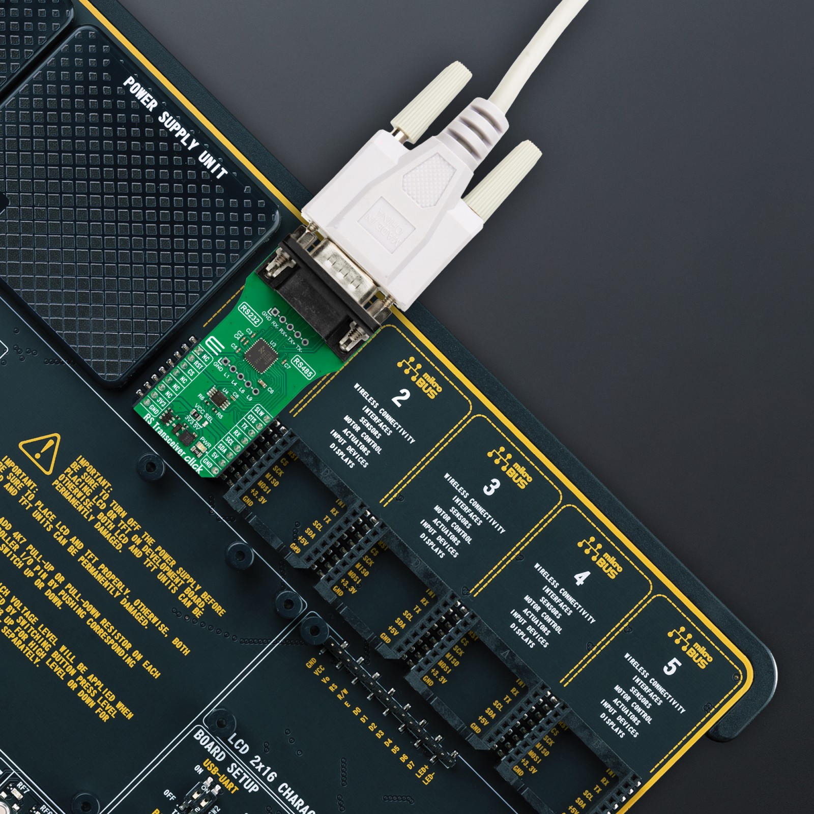
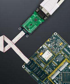
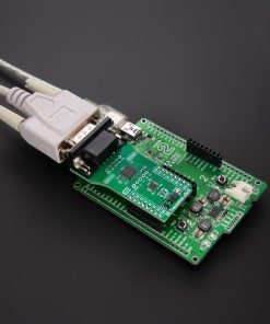
Depending on the development board you are using, you may need USB UART click, USB UART 2 Click or RS232 Click to connect to your PC, for development systems with no UART to USB interface available on the board. UART terminal is available in all MIKROE compilers.
mikroSDK
This Click board™ is supported with mikroSDK – MIKROE Software Development Kit. To ensure proper operation of mikroSDK compliant Click board™ demo applications, mikroSDK should be downloaded from the LibStock and installed for the compiler you are using.
For more information about mikroSDK, visit the official page.