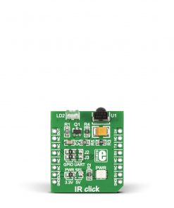
NOTE: If you are interested in Riverdi displays an adapter board that you can use we suggest you our latest RiBUS click board.
How does it work?
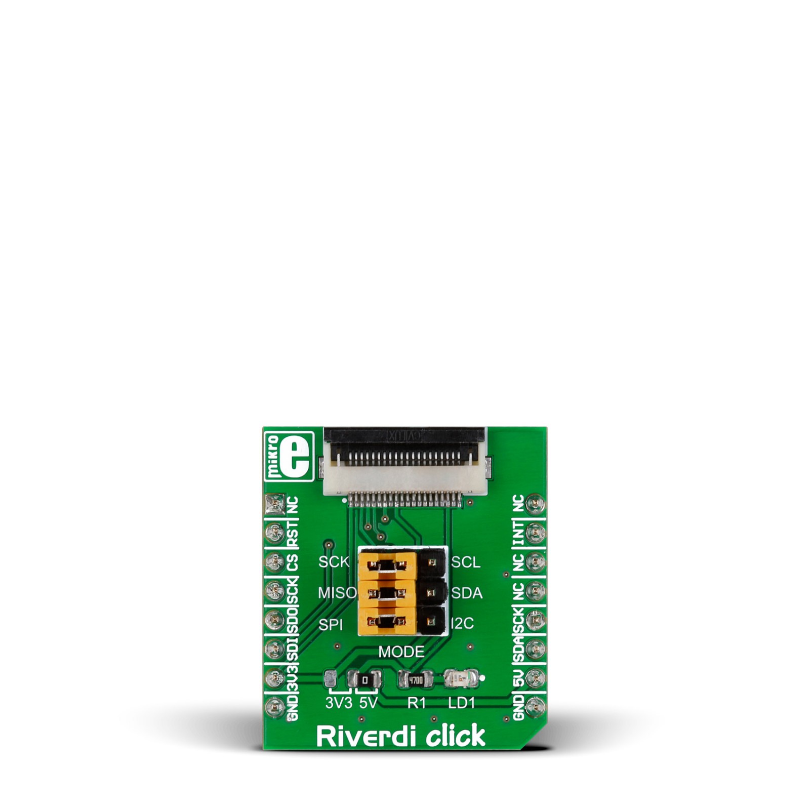
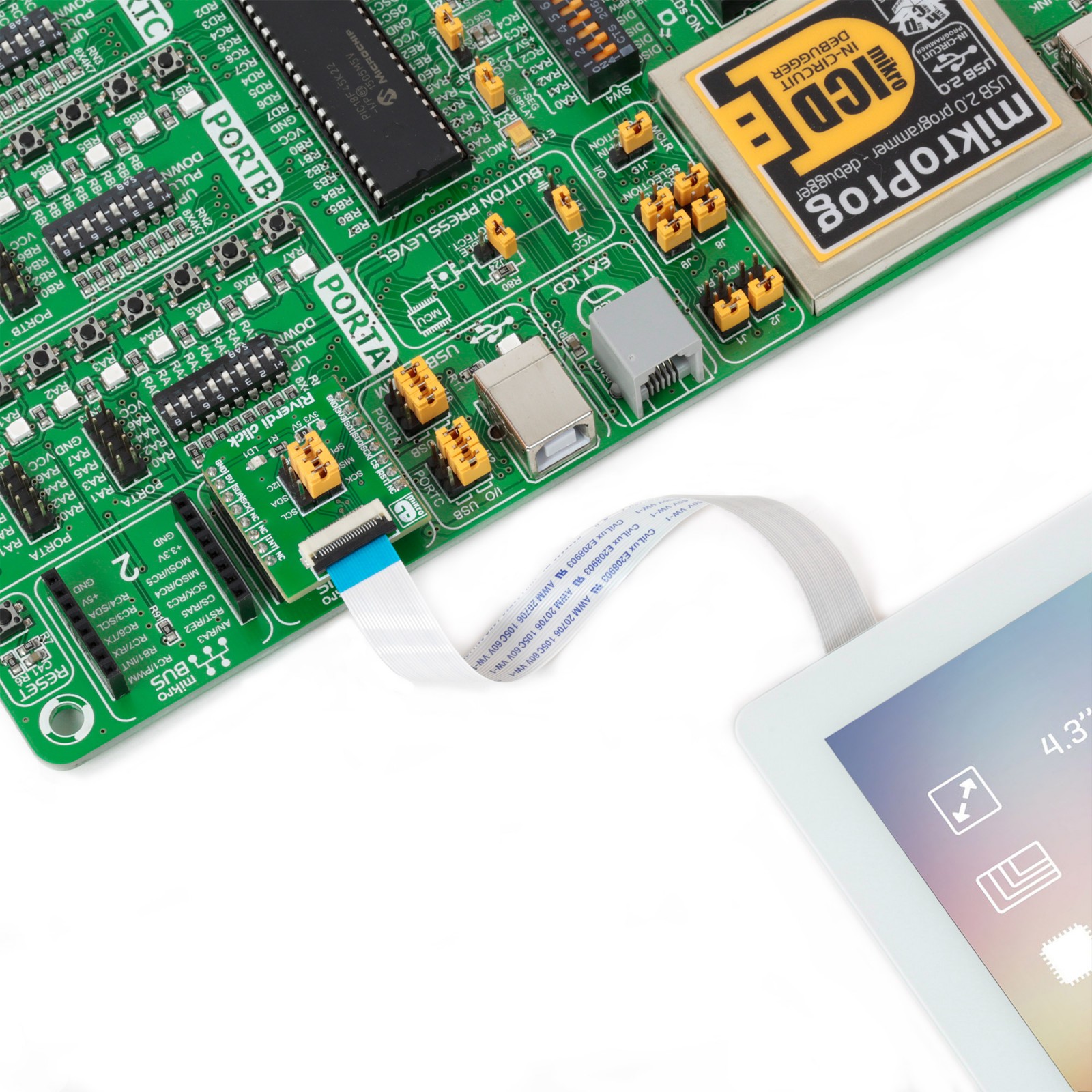
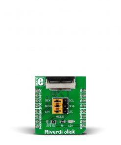
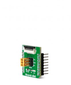
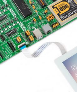
Riverdi Click is based on the ZIF20 connector and necessary circuits for interfacing Riverdi’s displays based on the FT8xx graphic controller. By utilizing the Riverdi Click, it is possible to develop an MCU firmware application that can interact with the graphic objects on the Riverdi Display Module over the mikroBUS™. This significantly simplifies the application design while reducing the processing load on the host MCU, allowing amazing graphically based applications to be created, even with slower 8-bit MCUs. We have more than 20 Riverdi TFT displays available in different sizes, from 7’’ to 2.8’’ screens. Choose from various frames – metal mounting frames for industrial use, white bezels for homes and offices, and many more.
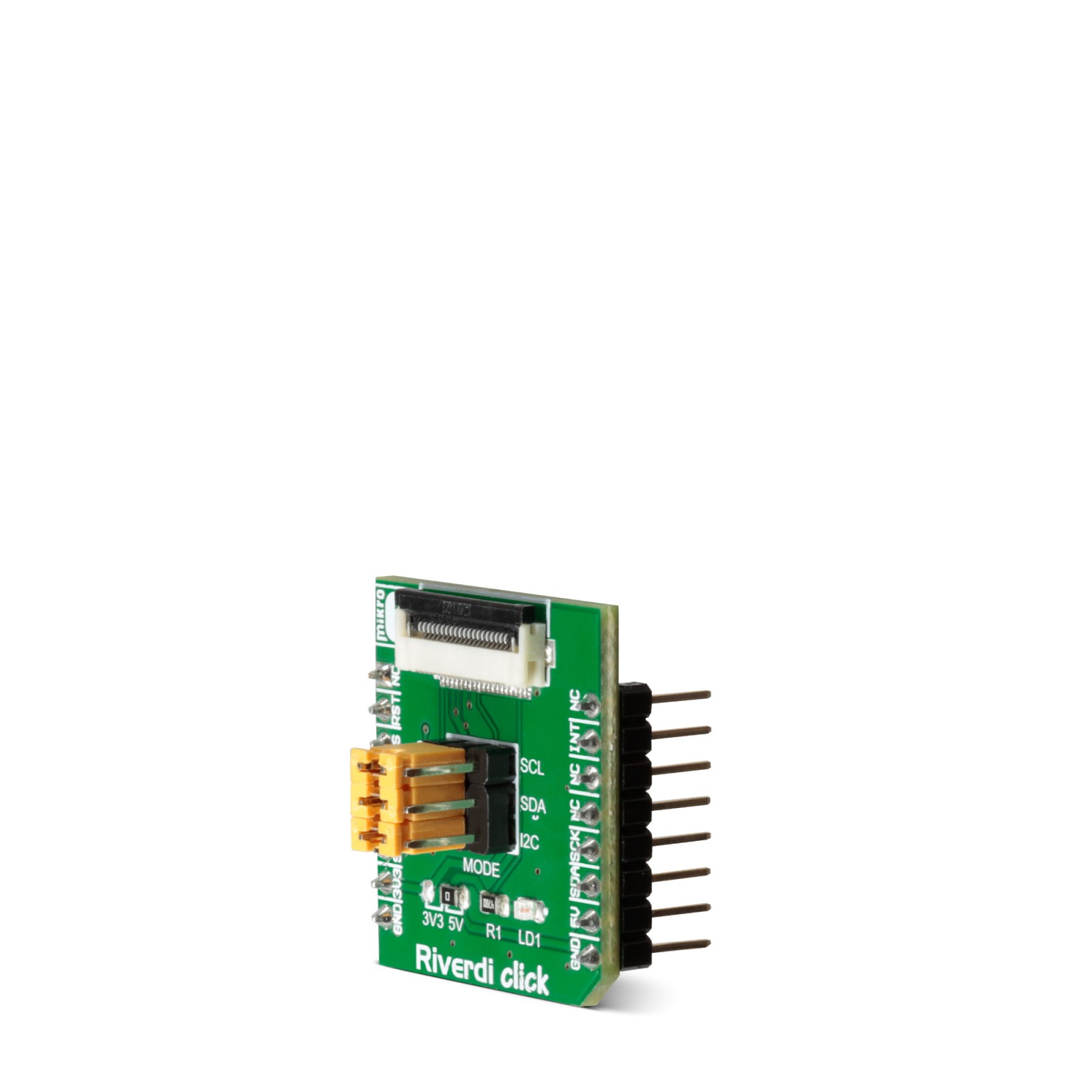
Riverdi Click can use either an I2C or SPI interface to communicate with the host MCU, which depends on the chosen display itself. Riverdi Click is equipped with MODE jumpers to set the required interface. All jumpers should be set in the proper position for the display to work properly. Riverdi Click comes with a flat flexible cable for the onboard YIF20 connector.
This Click board™ can operate with either 3.3V or 5V logic voltage levels selected via the 3V3 5V jumper. This way, both 3.3V and 5V capable MCUs can use the communication lines properly. However, the Click board™ comes equipped with a library containing easy-to-use functions and an example code that can be used as a reference for further development.
Specifications
Type
Adapter,Displays,TFT
Applications
Can be used for the development of graphical user interfaces that are based on Riverdi displays and any of the MCUs we offer
On-board modules
None
Key Features
Selectable SPI/I2C interface of the FT8xx graphic driver of the Riverdi displays, ZIF20 connector for interfacing Riverdi displays
Interface
I2C,SPI
Feature
No ClickID
Compatibility
mikroBUS™
Click board size
S (28.6 x 25.4 mm)
Input Voltage
3.3V or 5V
Pinout diagram
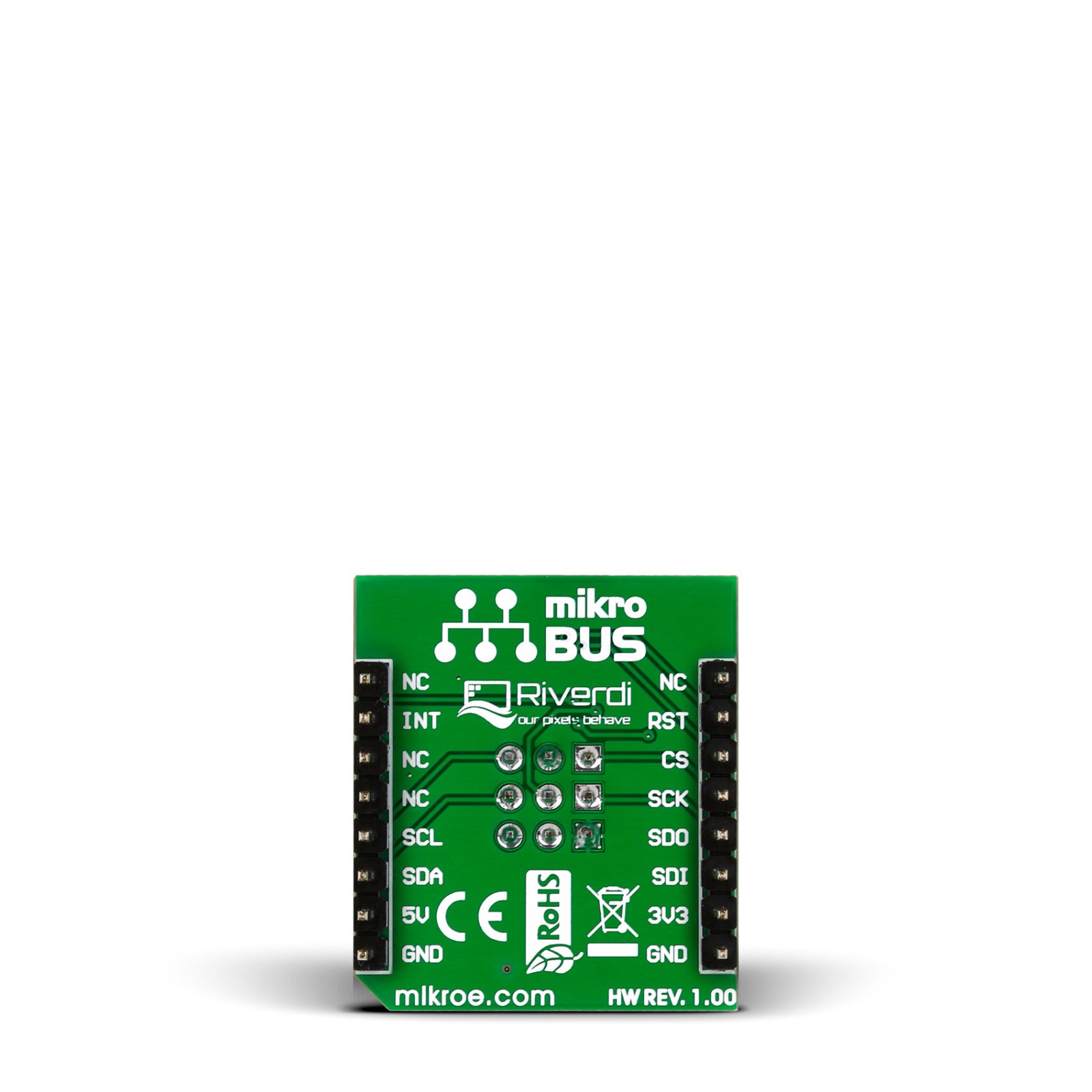
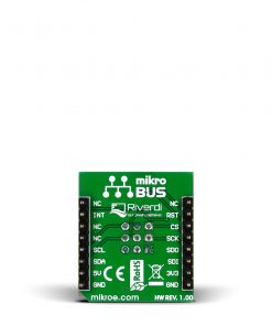
This table shows how the pinout on Riverdi Click corresponds to the pinout on the mikroBUS™ socket (the latter shown in the two middle columns).
Onboard settings and indicators
Label | Name | Default | Description |
---|---|---|---|
LD1 | PWR | – | Power LED Indicator |
J1-J3 | MODE | Left | Communication Interface Selection SPI/I2C: Left position SPI, Right position I2C |
– | – | Left | Power Voltage Level Selection 3V3/5V: Left position 3V3, Right position 5V |
Riverdi Click electrical specifications
Description | Min | Typ | Max | Unit |
---|---|---|---|---|
Supply Voltage | 3.3 | – | 5 | V |