How does it work?
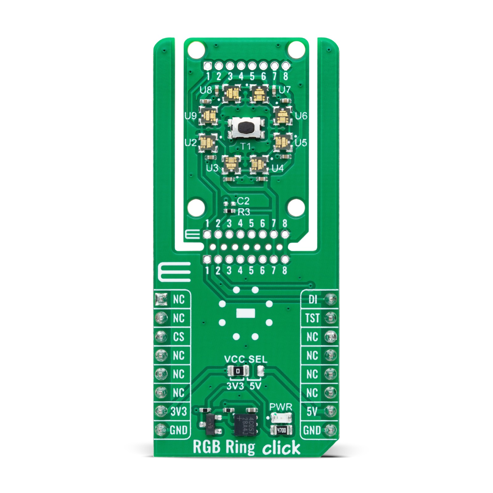
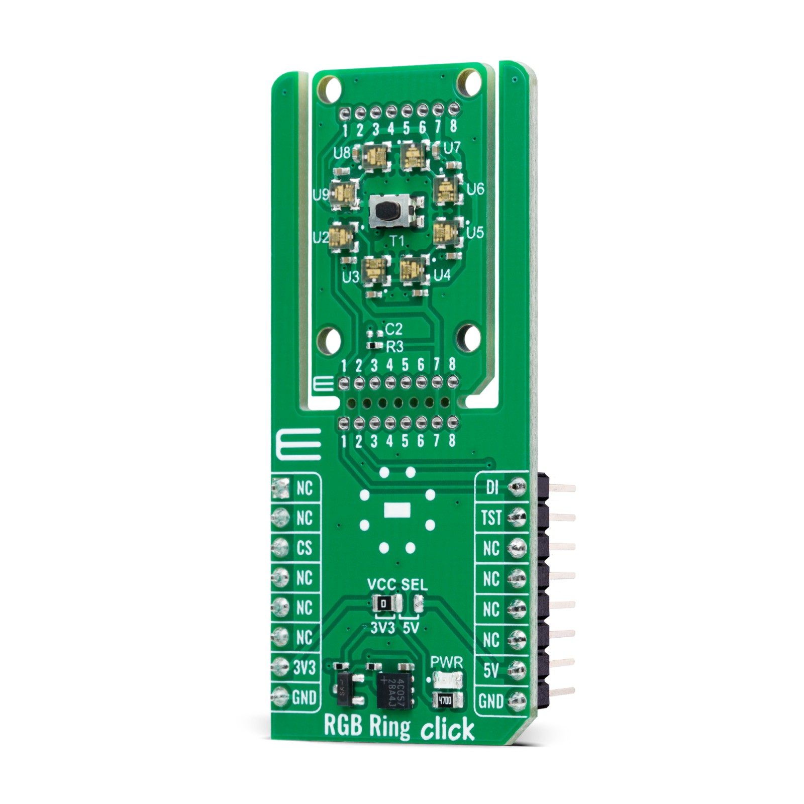
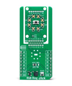
RGB Ring Click is based on a circle of eight RGB LEDs (WL-ICLED 1312020030000) from Würth Elektronik, specially designed for dynamic and colorful lighting applications. These LEDs incorporate an integrated circuit (IC), often called addressable or smart LEDs, allowing for individual control of each diode’s red, green, and blue components through pulse width modulation (PWM). This enables precise control over color mixing, creating a broad spectrum of color outputs. Due to its accurate color management and versatile design, this Click board™ is perfect for use across various consumer electronics and industrial settings like ambient lighting, visual indicators, and many more.
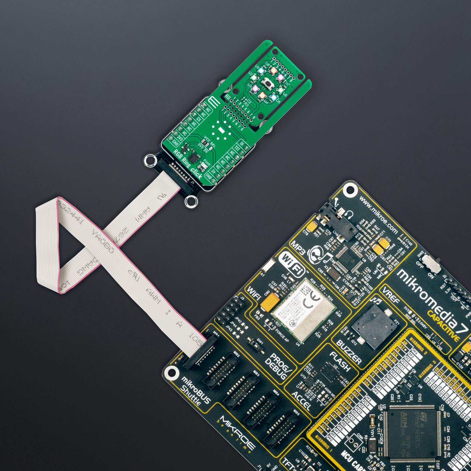
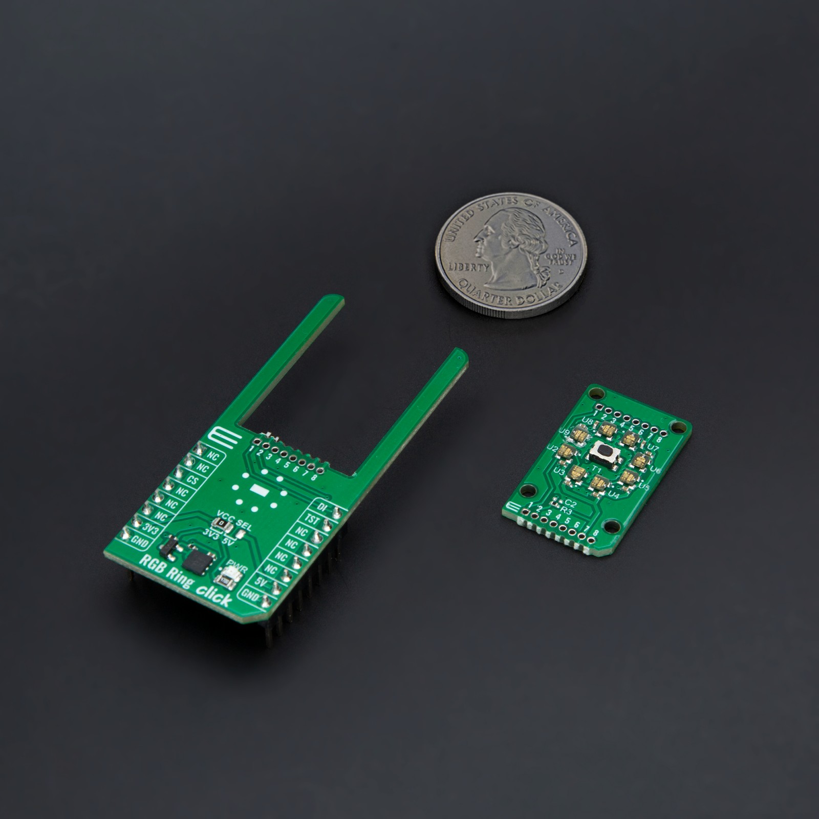
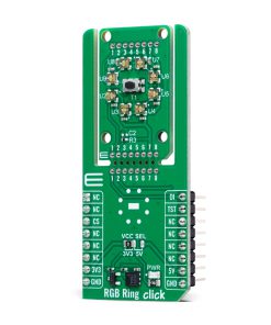
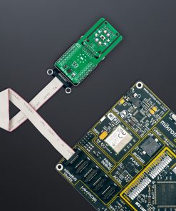
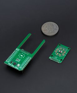
RGB Ring Click is designed in a unique format supporting the newly introduced MIKROE feature called “Click Snap.” Unlike the standardized version of Click boards, this feature allows the main IC area to become movable by breaking the PCB, opening up many new possibilities for implementation. Thanks to the Snap feature, the 1312020030000s can operate autonomously by accessing its signals directly on the pins marked 1-8. Additionally, the Snap part includes a specified and fixed screw hole position, enabling users to secure the Snap board in their desired location.
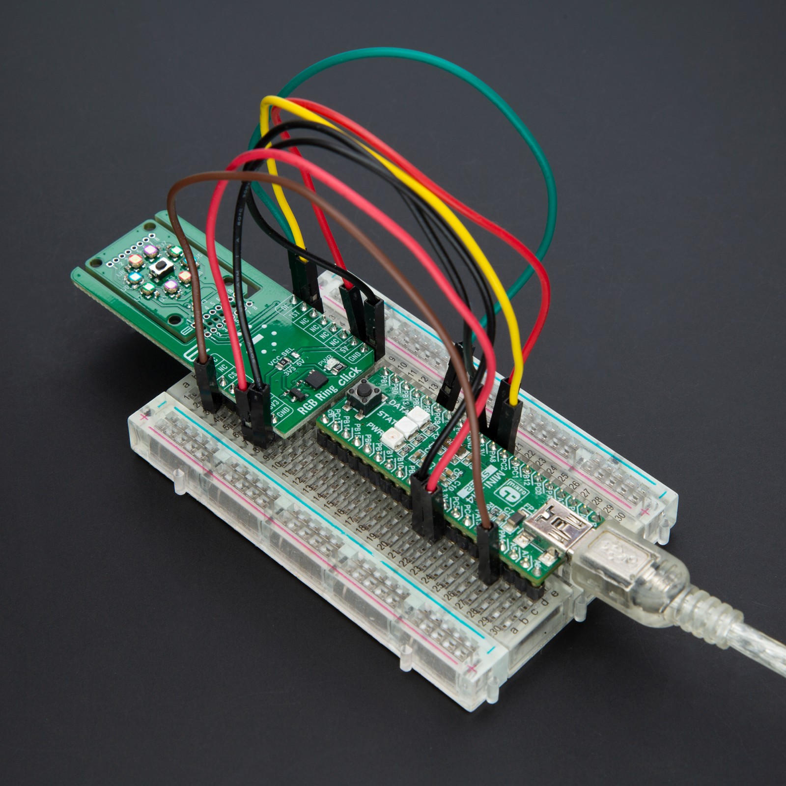
These LEDs are designed to be controlled through a single-wire communication protocol. The control signal with the desired color and brightness is sent from an MCU over the DI pin to the first LED. This information is retransmitted via daisy-chain connection to the following LEDs so that all subsequent components do not require an additional connection to the host MCU.
A special feature of this board is a button T1 located within the circle of RGB LEDs. When using the provided code example from MIKROE, pressing the button triggers the transition to the next color in the array. However, users can also repurpose the button for other functions, adding flexibility for various applications. With the help of the TST pin, it is possible to digitally monitor button presses and use it as an interrupt. In addition, there is also an unpopulated header at the top of the board, allowing for daisy-chaining and control of multiple Snap units in a series.
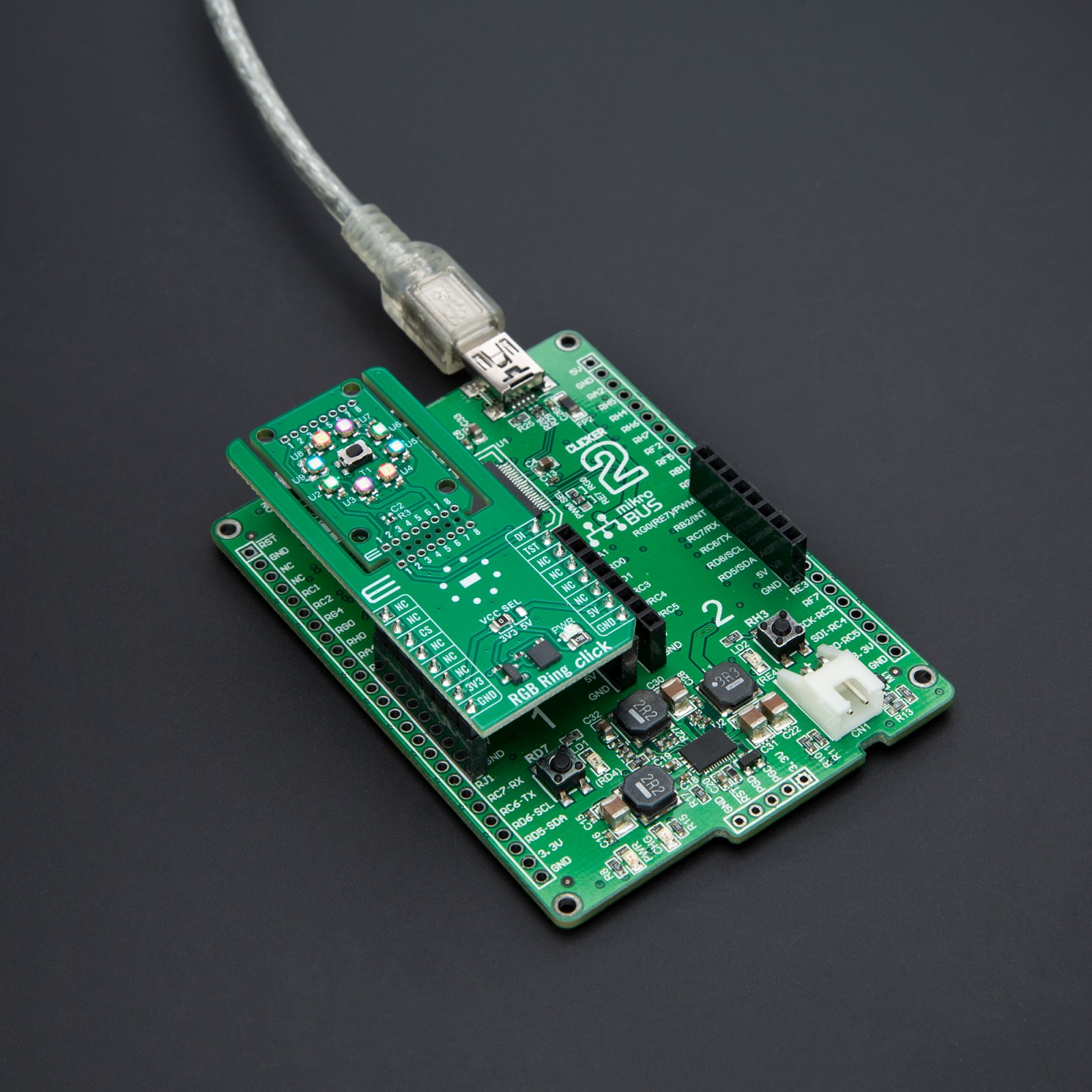
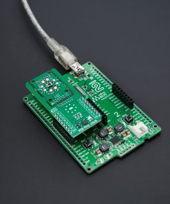
This Click board™ can operate with either 3.3V or 5V logic voltage levels selected via the VCC SEL jumper. This way, both 3.3V and 5V capable MCUs can use the communication lines properly. Also, this Click board™ comes equipped with a library containing easy-to-use functions and an example code that can be used as a reference for further development.
Click Snap
Click Snap is an innovative feature of our standardized Click add-on boards, introducing a new level of flexibility and ease of use. This feature allows for easy detachment of the main sensor area by simply snapping the PCB along designated lines, enabling various implementation possibilities. For detailed information about Click Snap, please visit the official page dedicated to this feature.
Specifications
Type
LED Matrix
Applications
Ideal for ambient lighting, visual indicators, and decorative lighting in consumer electronics and industrial environments
On-board modules
1312020030000 – WL-ICLED integrated controller within LED from Würth Elektronik
Key Features
Individually addressable RGB LEDs with integrated IC, compatibility with both 3.3V and 5V logic systems, single-wire communication protocol, Click Snap feature, header for cascading multiple Snap units, and more
Interface
PWM
Feature
Click Snap,ClickID
Compatibility
mikroBUS™
Click board size
L (57.15 x 25.4 mm)
Input Voltage
3.3V or 5V
Pinout diagram
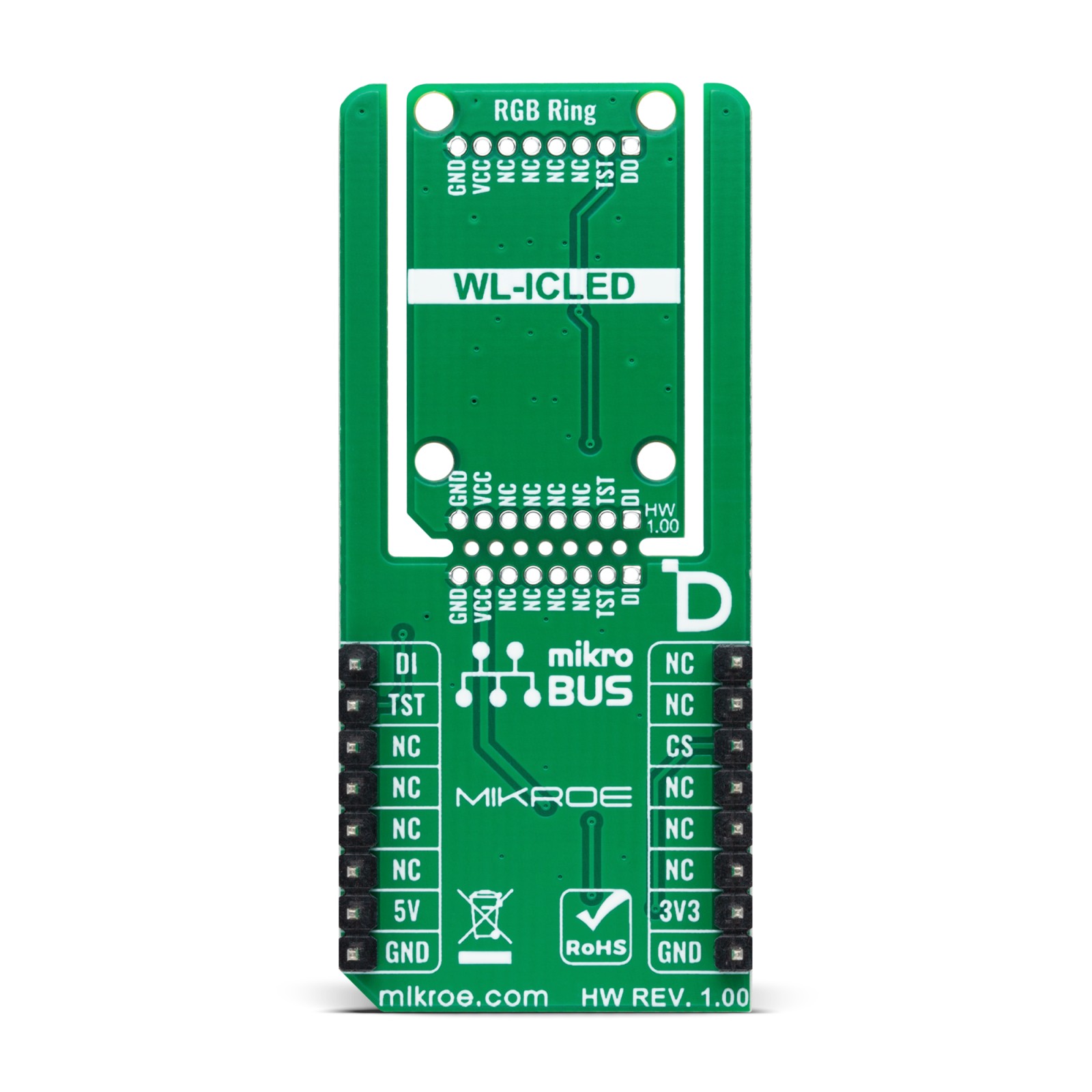
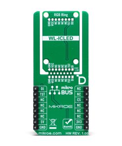
This table shows how the pinout on RGB Ring Click corresponds to the pinout on the mikroBUS™ socket (the latter shown in the two middle columns).
Onboard settings and indicators
Label | Name | Default | Description |
---|---|---|---|
LD1 | PWR | – | Power LED Indicator |
JP1 | VCC SEL | Left | Power Voltage Level Selection 3V3/5V: Left position 3V3, Right position 5V |
RGB Ring Click electrical specifications
Description | Min | Typ | Max | Unit |
---|---|---|---|---|
Supply Voltage | 3.3 | – | 5 | V |
Software Support
We provide a library for the RGB Ring Click as well as a demo application (example), developed using MIKROE compilers. The demo can run on all the main MIKROE development boards.
Package can be downloaded/installed directly from NECTO Studio Package Manager (recommended), downloaded from our LibStock™ or found on MIKROE github account.
Library Description
This library contains API for RGB Ring Click driver.
Key functions
-
rgbring_get_int_pin
This function returns the INT pin logic state. -
rgbring_set_led_color
This function sets the color of the selected LED in the LED matrix. -
rgbring_write_led_matrix
This function writes the LED matrix data from the click context object.
Example Description
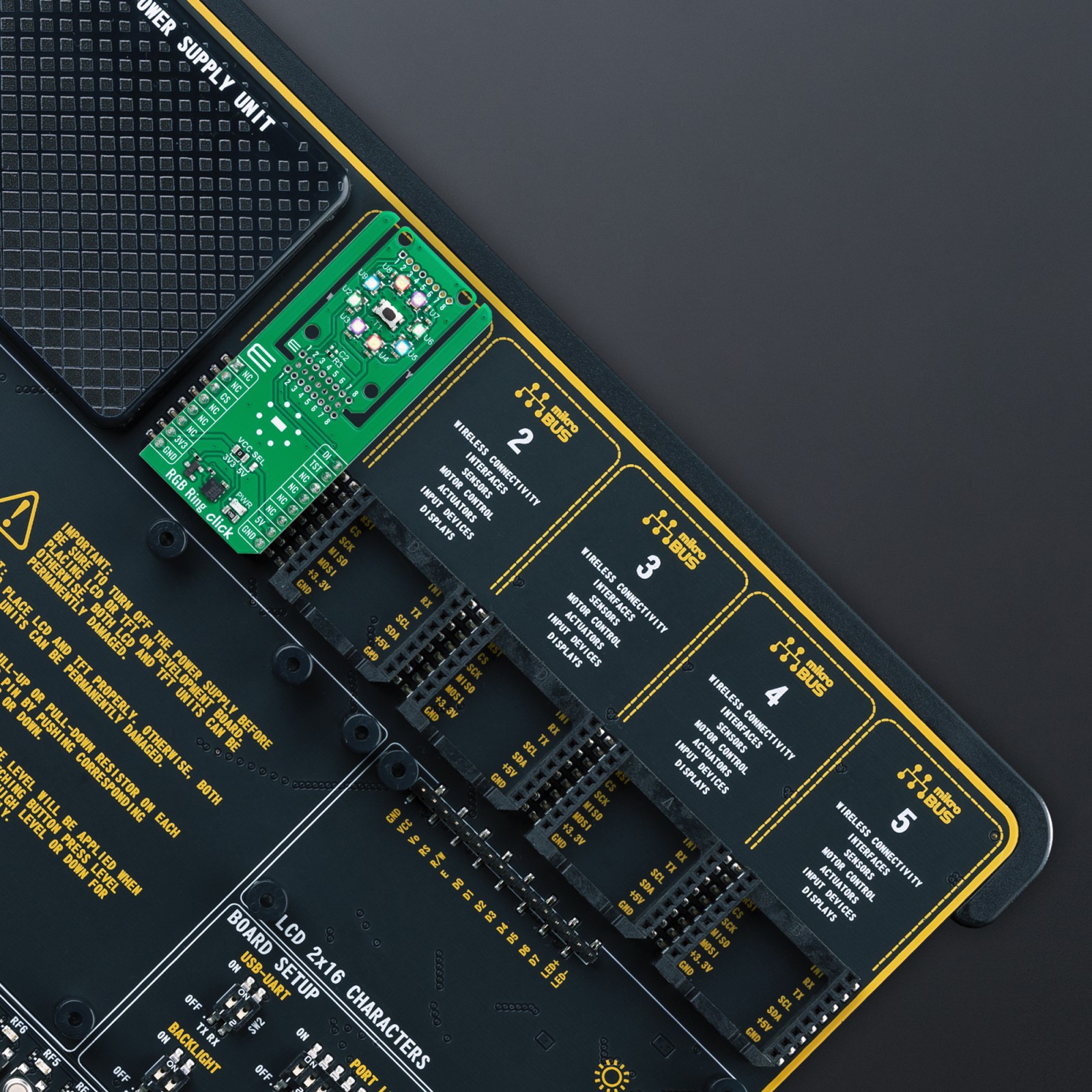
This example demonstrates the use of RGB Ring Click by controling an RGB ring by cycling through a set of predefined colors. Each color is displayed by lighting up the LEDs in sequence around the ring. After the last LED is lit, the code waits for a button press before moving on to the next color in the sequence. The button press triggers the transition to the next color in the array.
void application_task ( void )
{
static uint32_t color_num = 0;
static int8_t led_cnt = 0;
log_printf( &logger, " Color: %s [%.6LX]rn", color[ color_num ].name, color[ color_num ].rgb );
Delay_ms ( 100 );
for ( led_cnt = RGBRING_LED_7; led_cnt >= RGBRING_LED_0; led_cnt-- )
{
rgbring_set_led_color ( &rgbring, led_cnt, color[ color_num ].rgb );
rgbring_write_led_matrix ( &rgbring );
Delay_ms ( 100 );
}
if ( ++color_num >= RGBRING_NUM_COLORS )
{
color_num = 0;
}
log_printf ( &logger, " Press button to change ring colorrnn" );
while ( RGBRING_BUTTON_RELESED == rgbring_get_int_pin ( &rgbring ) );
}
The full application code, and ready to use projects can be installed directly from NECTO Studio Package Manager (recommended), downloaded from our LibStock™ or found on MIKROE github account.
Other MIKROE Libraries used in the example:
- MikroSDK.Board
- MikroSDK.Log
- Click.RGBRing
Additional notes and informations
Depending on the development board you are using, you may need USB UART click, USB UART 2 Click or RS232 Click to connect to your PC, for development systems with no UART to USB interface available on the board. UART terminal is available in all MIKROE compilers.
mikroSDK
This Click board™ is supported with mikroSDK – MIKROE Software Development Kit. To ensure proper operation of mikroSDK compliant Click board™ demo applications, mikroSDK should be downloaded from the LibStock and installed for the compiler you are using.
For more information about mikroSDK, visit the official page.