Qi RX Click
R940.00 ex. VAT
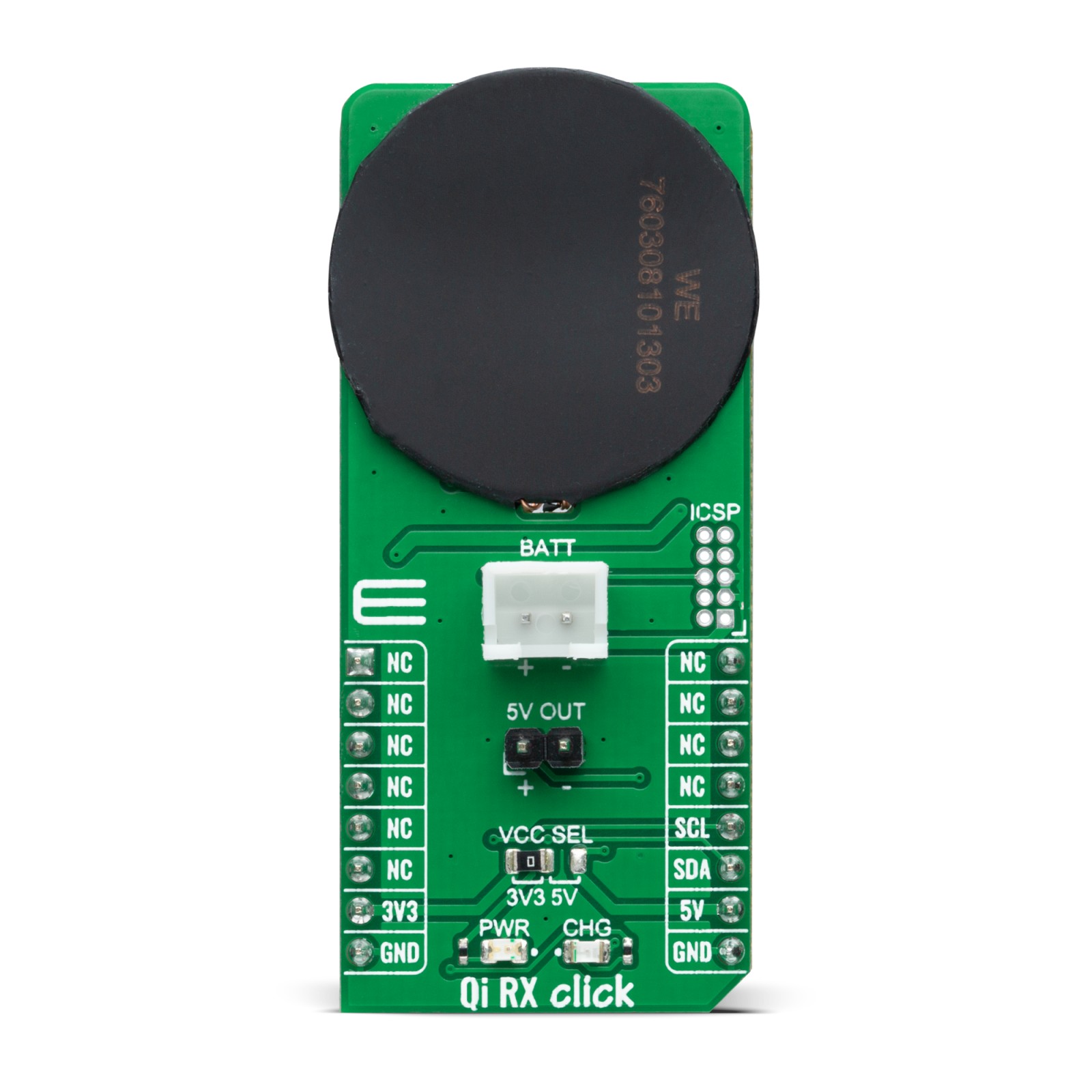
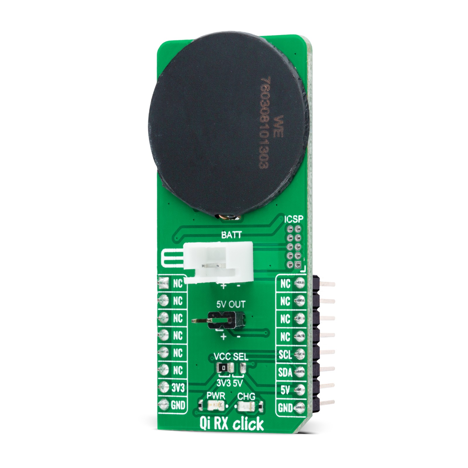
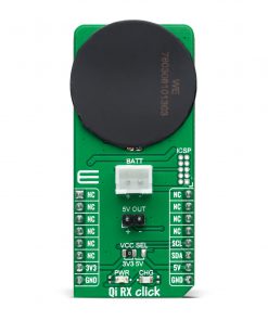
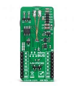
Qi RX Click is a compact add-on board made for the purpose of wireless power transfer. This board features the PIC16F15313, a general-purpose 8-bit MCU that makes a flexible, low-cost alternative to the wireless charging solutions based on ASICs from Microchip. It represents a simple, low-cost implementation of the Qi 1.1 5W wireless charging standard with the added functionality of a fully-featured Li-Ion charging controller. It can extend product life by reducing mechanical failures from connectors allowing the manufacture of devices truly resistant to water and dust. This Click board™ is suitable for wireless charging applications, cell phones, tablets, small hand-held devices, embedded electronics, and more.
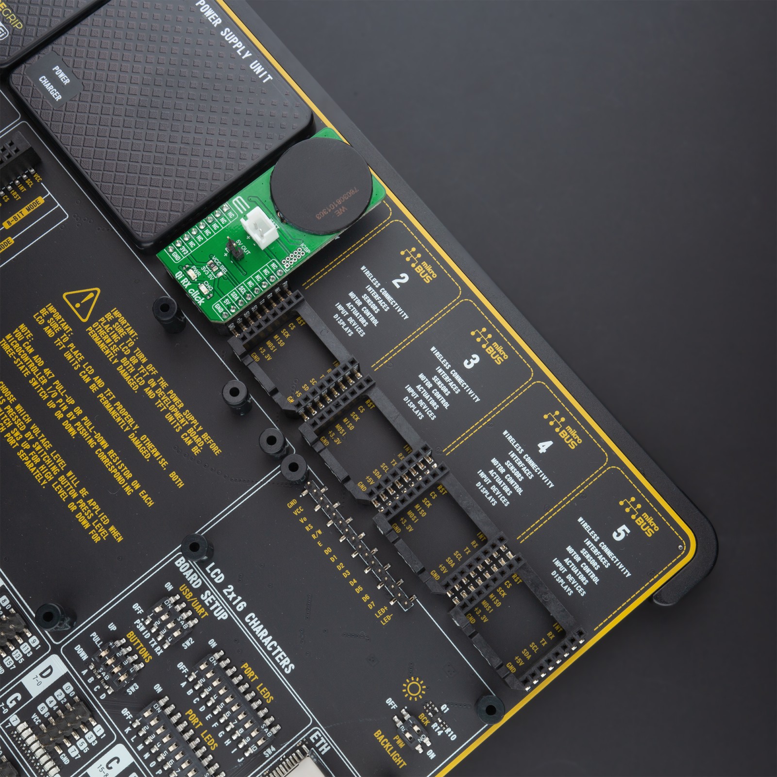
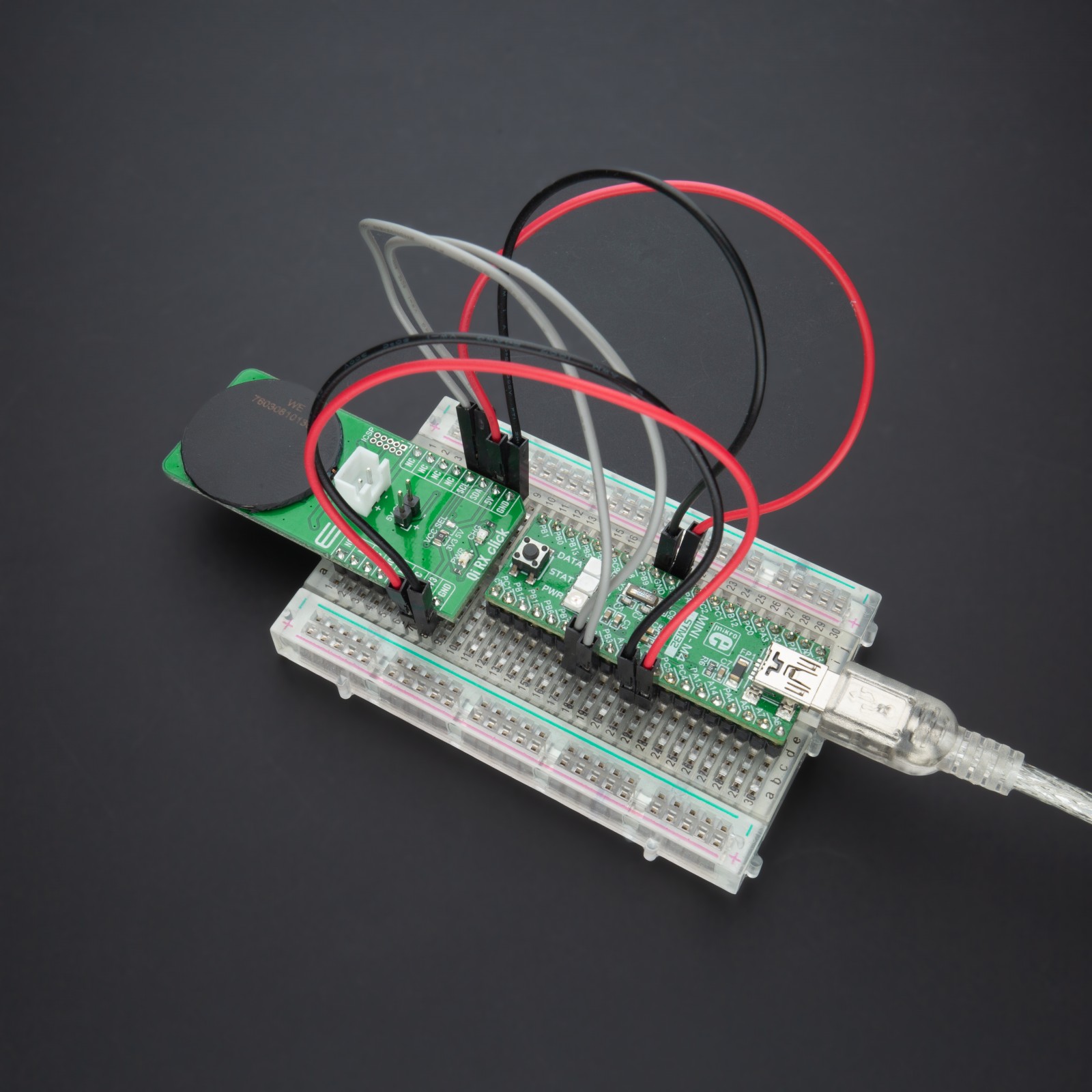
Qi RX Click is supported by a mikroSDK compliant library, which includes functions that simplify software development. This Click board™ comes as a fully tested product, ready to be used on a system equipped with the mikroBUS™ socket.
Stock: Lead-time applicable.
| 5+ | R893.00 |
| 10+ | R846.00 |
| 15+ | R799.00 |
| 20+ | R768.92 |
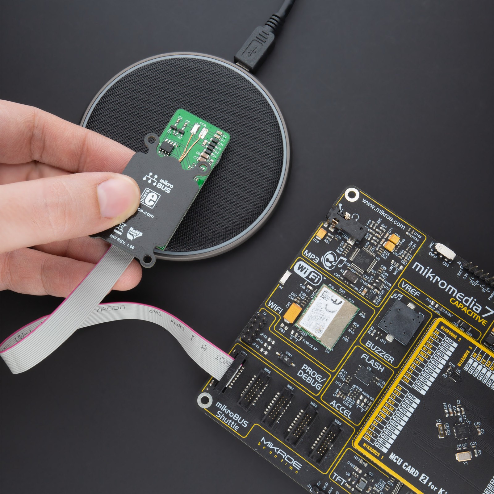
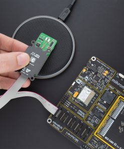
NOTE: Qi RX Click needs to be placed near the suitable Qi Transmitter, also known as the charging pad, to successfully harvest the transmitted power.
How does it work?
Qi RX Click is based on the PIC16F15313, a general-purpose 8-bit MCU that makes a flexible, low-cost alternative to the wireless charging solutions based on ASICs from Microchip. The Qi RX Click allows users to quickly add wireless charging functionality to their projects without dealing with complex specific protocols or state machines. It is implemented using a general-purpose 8-bit MCU compatible with the Qi 1.1 (5W) standard that can be used in conjunction with any Qi 1.1 compatible wireless charging transmitters with the added functionality of a fully-featured Li-Ion charging controller.

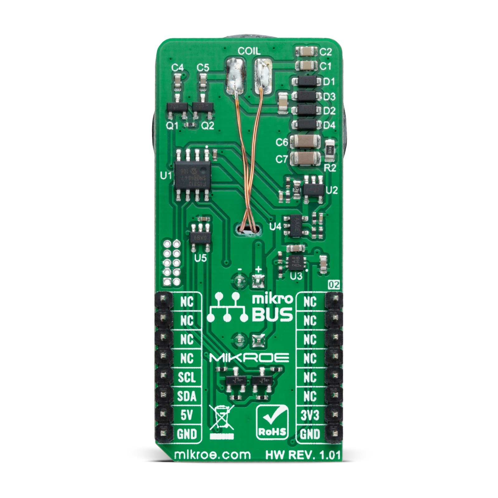
Wireless charging uses the principle of magnetic induction to transfer power, which is similar to a conventional AC transformer where the receiver and the transmitter coils representing the transformer windings. The high-frequency signal of the Receiver Coil is rectified by a simple full-bridge rectifier implemented with four Schottky diodes (D1-D4), which output voltage is then monitored by the PIC16F15313 through a simple resistive divider R4 and R5. The communication with the base transmitter is implemented using Amplitude Shift Keying (ASK), as recommended by the Qi 1.1 standard, with two low-power MOSFETs (Q1 and Q2) and two capacitors (C4 and C5) used to modulate the absorbed power.
The rectified voltage is also applied at the input of the MCP1755, a low drop-out voltage regulator from Microchip, that supplies the 5V voltage for the battery charger and the PIC16F15313 up to 300mA. This LDO is associated with the charge LED indicator labeled as CHG that will indicate the charging progress and turns off once the battery charging is finished. The battery charging functionality is provided by the MCP73830, a single-cell Li-Ion/Li-Polymer battery charge management controller from Microchip.
The input current is measured by the PIC16F15313 using a shunt resistor R2 and the MCP6001, a single general-purpose OpAmp offering rail-to-rail input and output up to 6V from Microchip. The gain of this amplifier is set to 10. Measurement of the input current is necessary to accurately calculate input power and implement Foreign Object Detection (FOD) function using the power loss method.
Qi RX Click communicates with MCU using the MCP3221, a successive approximation A/D converter with a 12-bit resolution from Microchip. This device provides one single-ended input with very low-power consumption, a low maximum conversion current, and a Standby current of 250 μA and 1 μA. Data can be transferred at rates of up to 100 kbit/s in the Standard and 400 kbit/s in the Fast Mode. Also, maximum sample rates of 22.3 kSPS with the MCP3221 are possible in a Continuous-Conversion Mode with a clock rate of 400 kHz.
This Click board™ is designed to operate with both 3.3V and 5V logic voltage levels selected via the VCC SEL jumper. It allows for both 3.3V and 5V capable MCUs to use the I2C communication lines properly. However, the Click board™ comes equipped with a library that contains easy to use functions and an example code which can be used, as a reference, for further development.
Specifications
Type
Wireless Charging
Applications
Can be used for wireless charging applications, cell phones, tablets, small hand-held devices, embedded electronics, and more.
On-board modules
Qi RX Click is based on the PIC16F15313, a general-purpose 8-bit MCU that makes a flexible, low-cost alternative to the wireless charging solutions based on ASICs from Microchip.
Key Features
Fully-featured Li-Ion charging, foreign Object Detection (FOD) feature, integrated 5W Qi wireless power receiver, minimize cost, extend product life, and more.
Interface
I2C
Feature
No ClickID
Compatibility
mikroBUS™
Click board size
L (57.15 x 25.4 mm)
Input Voltage
3.3V or 5V
Pinout diagram
This table shows how the pinout on Qi RX Click corresponds to the pinout on the mikroBUS™ socket (the latter shown in the two middle columns).
Onboard settings and indicators
| Label | Name | Default | Description |
|---|---|---|---|
| LD1 | PWR | – | Power LED Indicator |
| LD2 | CHG | – | Charge LED Indicator |
| JP1 | VCC SEL | Left | Power Supply Voltage Selection 3V3/5V: Left position 3V3, Right position 5V |
| J1 | 5V OUT | Populated | VOUT Header |
| J2 | ICSP | Unpopulated | PROG/DEBUG Header |
Qi RX Click electrical specifications
| Description | Min | Typ | Max | Unit |
|---|---|---|---|---|
| Supply Voltage | -0.3 | – | 6.5 | V |
| RX Coil Output Current | – | – | 1.5 | A |
| Battery Charge Voltage | – | 3.7 | 4.2 | V |
| Baterry Charge Output Current | – | – | 1 | A |
| Operating Temperature Range | -40 | – | +125 | °C |
Software Support
We provide a library for the Qi RX Click on our LibStock page, as well as a demo application (example), developed using MikroElektronika compilers. The demo can run on all the main MikroElektronika development boards.
Library Description
The library covers all the necessary functions that enables the usage of the Qi RX Click board™. It offers reading from output register and calculations that result in relatively accurate measurement of connected batteries voltage.
Key functions:
uint16_t qirx_read_data ( );– Function is used to read raw data from MCP3221.uint16_t qirx_read_voltage ( uint16_t v_ref );– Function is used to calculate voltage of the connected battery.
Examples description
The application is composed of three sections :
- System Initialization – Initializes I2C module and LOG structure.
- Application Initialization – Initalizes I2C driver and makes an initial log.
- Application Task – This example shows the capabilities of the Qi RX Click by measuring voltage of the connected battery. In order to get correct calculations user should change “v_ref” value to his own power supply voltage.
void application_task ( )
{
    voltage = qirx_read_voltage( v_ref );
    WordToStr( voltage, log_txt );
    Ltrim( log_txt );
    mikrobus_logWrite( "Battery voltage: ", _LOG_TEXT );
    mikrobus_logWrite( log_txt, _LOG_TEXT );
    mikrobus_logWrite( "mV", _LOG_LINE );

    mikrobus_logWrite( "-----------------------", _LOG_LINE );
    Delay_ms( 2000 );
}
The full application code, and ready to use projects can be found on our LibStock page.
Other mikroE Libraries used in the example:
- I2C
- UART
- Conversions
Additional notes and informations
Depending on the development board you are using, you may need USB UART click, USB UART 2 click or RS232 click to connect to your PC, for development systems with no UART to USB interface available on the board. The terminal available in all MikroElektronika compilers, or any other terminal application of your choice, can be used to read the message.
mikroSDK
This Click board™ is supported with mikroSDK – MikroElektronika Software Development Kit. To ensure proper operation of mikroSDK compliant Click board™ demo applications, mikroSDK should be downloaded from the LibStock and installed for the compiler you are using.
For more information about mikroSDK, visit the official page.
Resources
Downloads
| Weight | 22 g |
|---|---|
| Brand | MikroElektronika |

