How does it work?
PWM Driver Click is based on the Si8711CC, a 5kV LED emulator input, open collector output isolator from Skyworks. Compared to the optocouplers, the Si8711CC is more resistant to temperature, age, and forward current effects. It has a longer service life, higher common-mode transient immunity, and more. The Si8711CC is based on proprietary CMOS isolation technology for low-power, high-speed operation and is resistant to wear-out effects that, in the case of optocouplers, degrade the performance. The Si8711CC features up to 5000VRMS isolation and 10kV surge protection, making it a perfect isolator. For controlling the devices, it is capable of data rates DC of up to 15Mbps, with a propagation delay of 30ns.
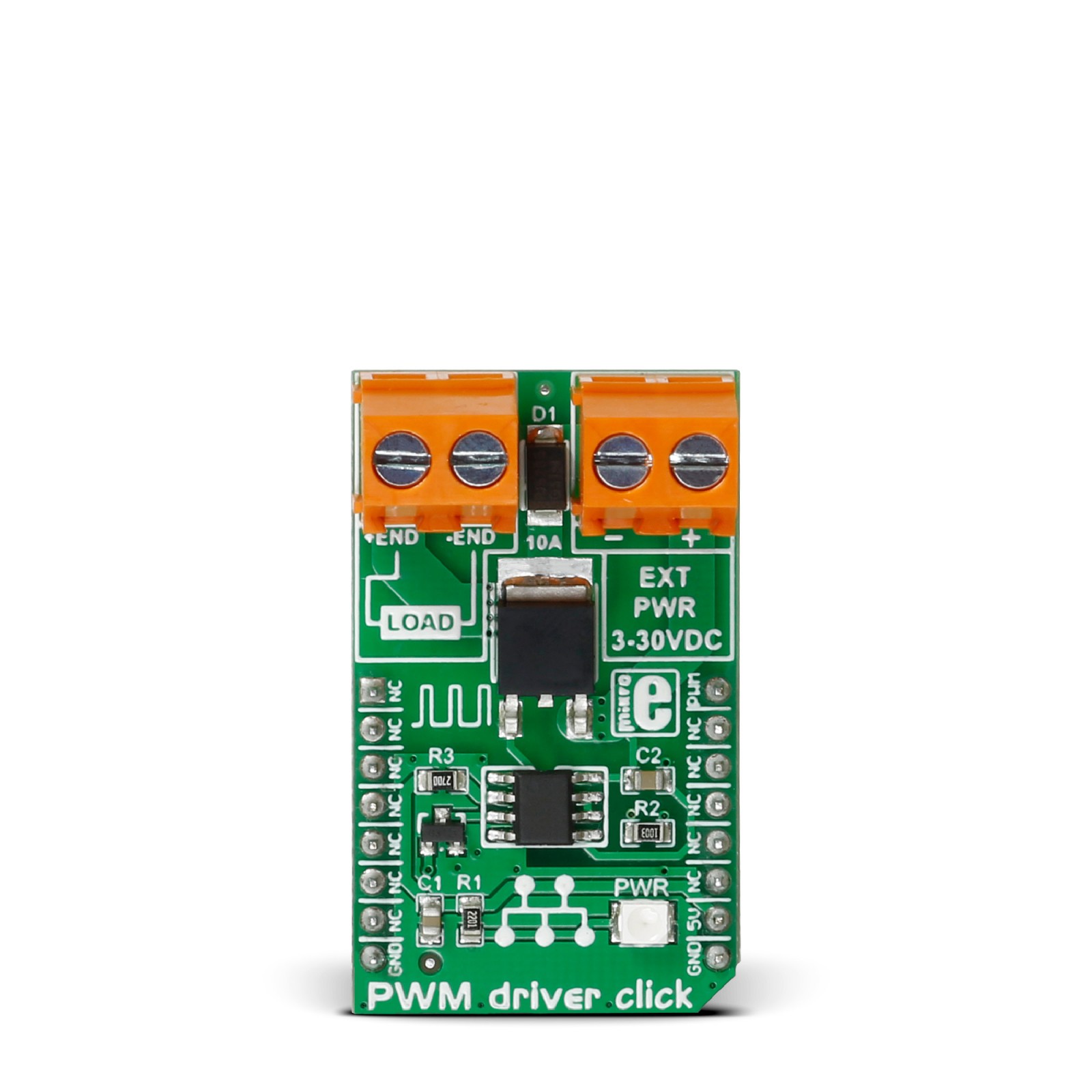
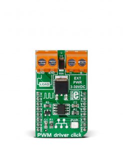
The Si8711CC controls the loads over the DMP3010LK3, a P-channel enhancement mode MOSFET from Diodes Incorporated. This fast-switching diode has ESD protected gate, low input capacitance, and low on-resistance, designed to maintain superior switching performance, making it ideal for high-efficiency power management applications. The PWM Driver Click comes with the screw terminals labeled LOAD (+END, -END) to connect the load, which the Si7811CC controls over the DMP3010LK3 diode, and EXT for external power supply. It is not recommended to use this Click board™ with loads over 50W as the MOSFET can get overheated; this, however, does not apply if the Click board™ is used as an ON/OFF switch.
The PWM Driver Click is controlled by the host MCU by PWM pulses over the PWM pin of the mikroBUS™ socket. The PWM pin does not have direct control over the Si8711CC but rather through the DMG3420U, an N-channel enhancement mode MOSFET from Diodes Incorporated. This diode shares many features with the one mentioned above, such as low on-resistance, low input capacitance, fast switching speed, and more.
This Click board™ can be operated only with a 5V logic voltage level. The board must perform appropriate logic voltage level conversion before using MCUs with different logic levels. However, the Click board™ comes equipped with a library containing functions and an example code that can be used, as a reference, for further development.
Specifications
Type
Brushed
Applications
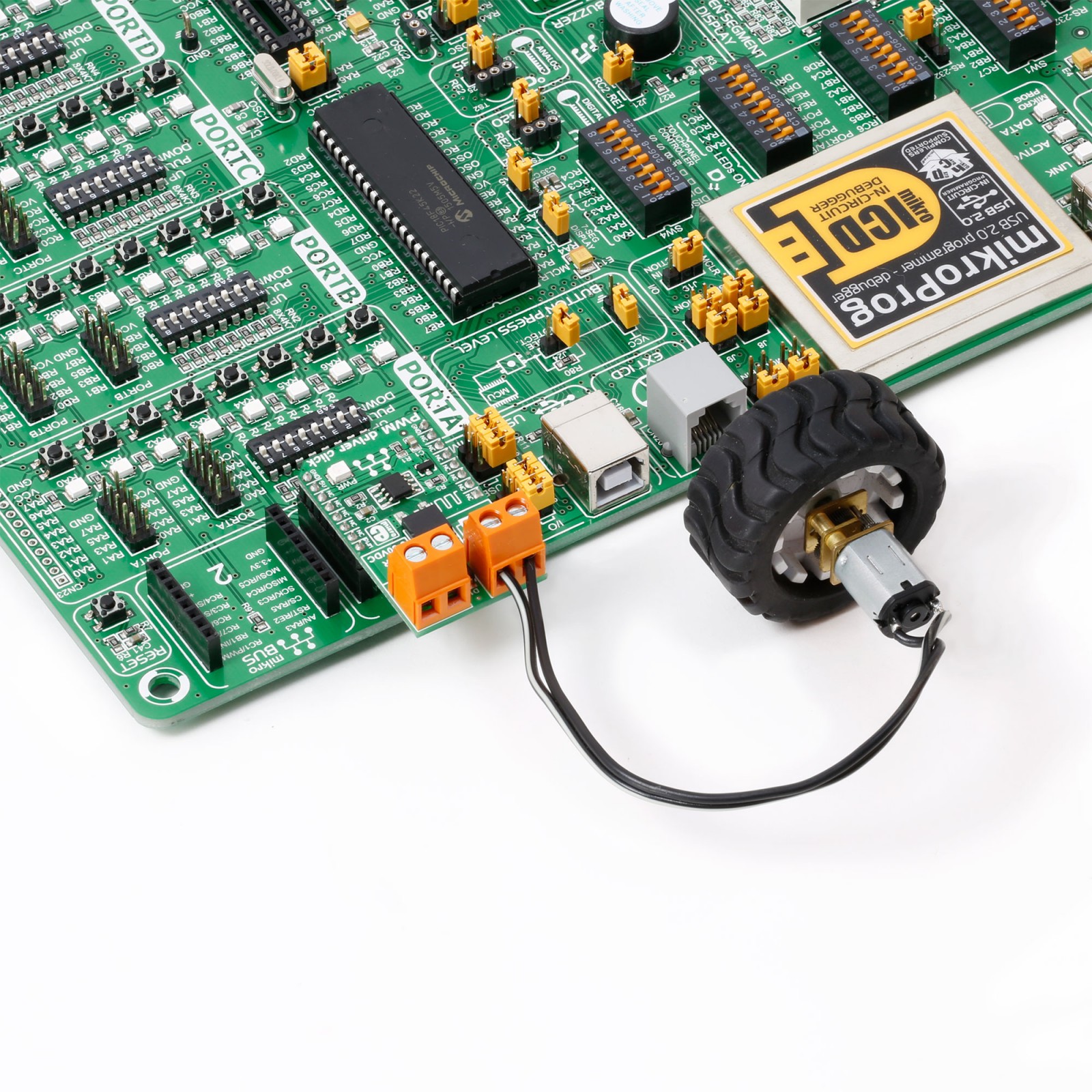
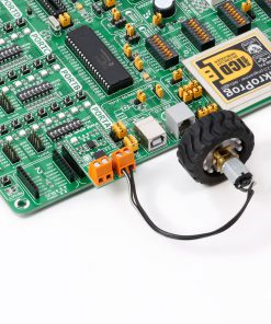
Can be used for the development of applications of controlling the DC motors with loads up to 10A, for electronic ON/OFF switches that control DC load circuits, light intensity control, and more
On-board modules
Si8711CC – 5kV LED emulator input, open collector output isolator from Skyworks
Key Features
Brushed DC motors control with loads up to 10A, and up to 50W, external power supply, ON/OFF DC switches over the 50W, two screw terminals, light intensity control for ambient-light scenarios, performance and reliability, and more
Interface
PWM
Feature
No ClickID
Compatibility
mikroBUS™
Click board size
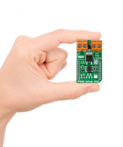
M (42.9 x 25.4 mm)
Input Voltage
5V
Pinout diagram
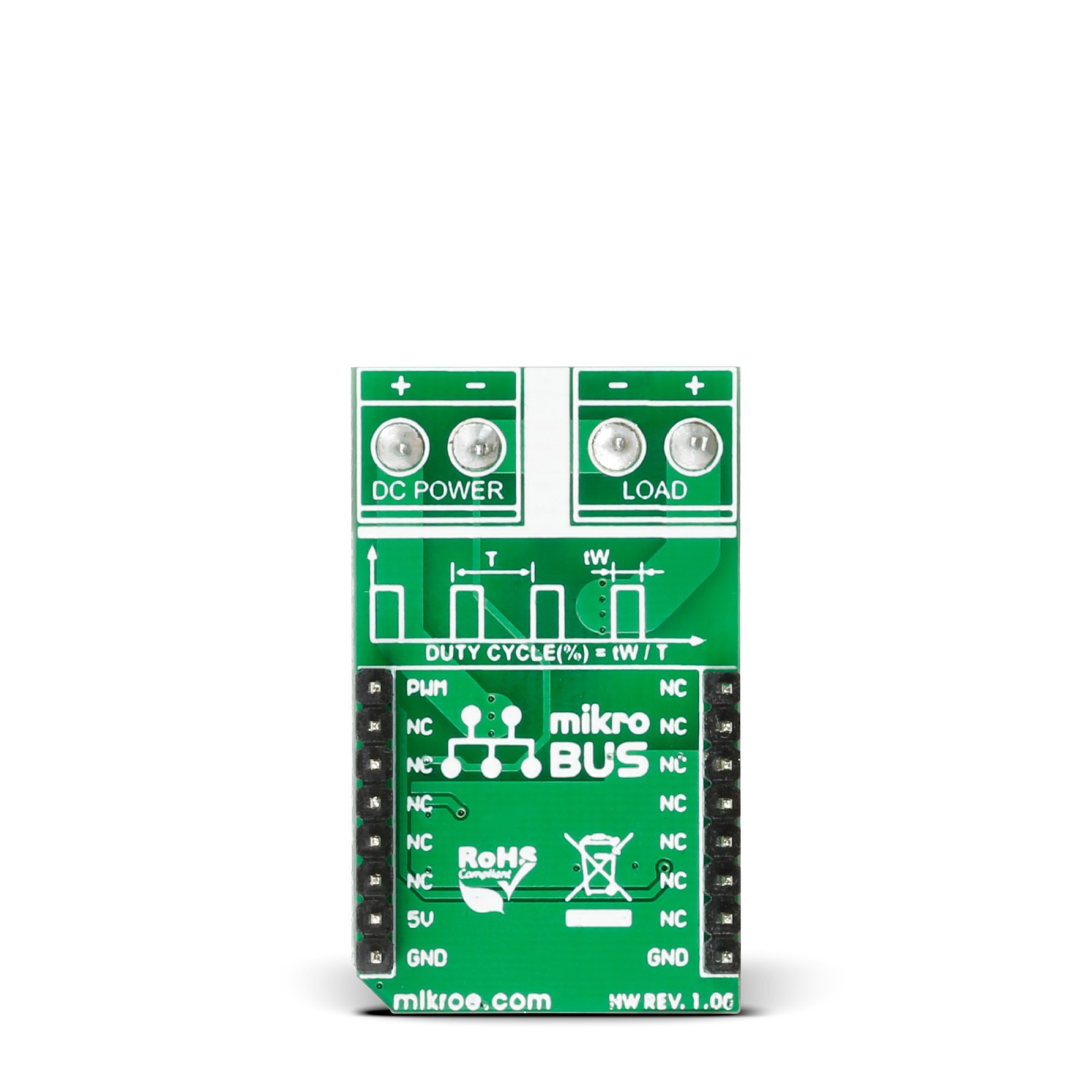
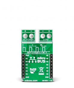
This table shows how the pinout on PWM driver Click corresponds to the pinout on the mikroBUS™ socket (the latter shown in the two middle columns).
Onboard settings and indicators
Label | Name | Default | Description |
---|---|---|---|
LD1 | PWR | – | Power LED Indicator |
Software Support
We provide a library for the Pwm Driver Click as well as a demo application (example), developed using MIKROE compilers. The demo can run on all the main MIKROE development boards.
Package can be downloaded/installed directly from NECTO Studio Package Manager(recommended), downloaded from our LibStock™ or found on Mikroe github account.
Library Description
This library contains API for Pwm Driver Click driver.
Key functions
-
Generic sets PWM duty cycle
-
Stop PWM module.
-
Start PWM module
Example Description
This application is controls the speed DC motors.
void application_task ( void )
{
// Task implementation.
log_printf( &logger," Light Intensity Rising rn " );
Delay_1sec( );
for ( duty_cycle = 0; duty_cycle < 1; duty_cycle += 0.1 )
{
pwmdriver_set_duty_cycle( &pwmdriver,duty_cycle );
log_printf( &logger," > rn " );
Delay_1sec( );
}
log_printf( &logger,"------------------------- rn " );
log_printf( &logger," Light Intensity Falling rn " );
Delay_1sec( );
for ( duty_cycle = 1; duty_cycle > 0; duty_cycle -= 0.1 )
{
pwmdriver_set_duty_cycle( &pwmdriver,duty_cycle );
log_printf( &logger," < rn " );
Delay_1sec( );
}
log_printf( &logger," rn " );
log_printf( &logger,"--------------------- rn " );
Delay_1sec( );
}
The full application code, and ready to use projects can be installed directly from NECTO Studio Package Manager (recommended), downloaded from our LibStock™ or found on Mikroe github account.
Other Mikroe Libraries used in the example:
- MikroSDK.Board
- MikroSDK.Log
- Click.PwmDriver
Additional notes and informations
Depending on the development board you are using, you may need USB UART click, USB UART 2 Click or RS232 Click to connect to your PC, for development systems with no UART to USB interface available on the board. UART terminal is available in all MIKROE compilers.
mikroSDK
This Click board™ is supported with mikroSDK – MIKROE Software Development Kit. To ensure proper operation of mikroSDK compliant Click board™ demo applications, mikroSDK should be downloaded from the LibStock and installed for the compiler you are using.
For more information about mikroSDK, visit the official page.