How does it work?
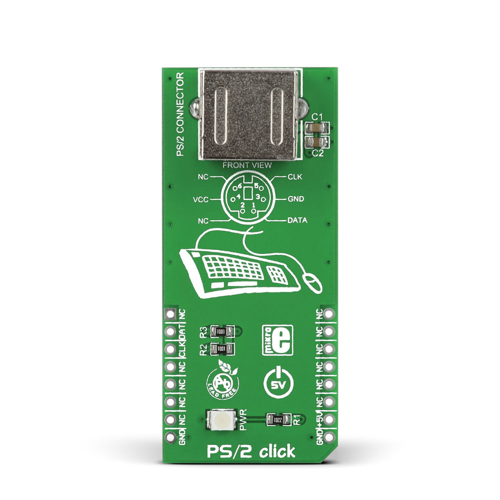
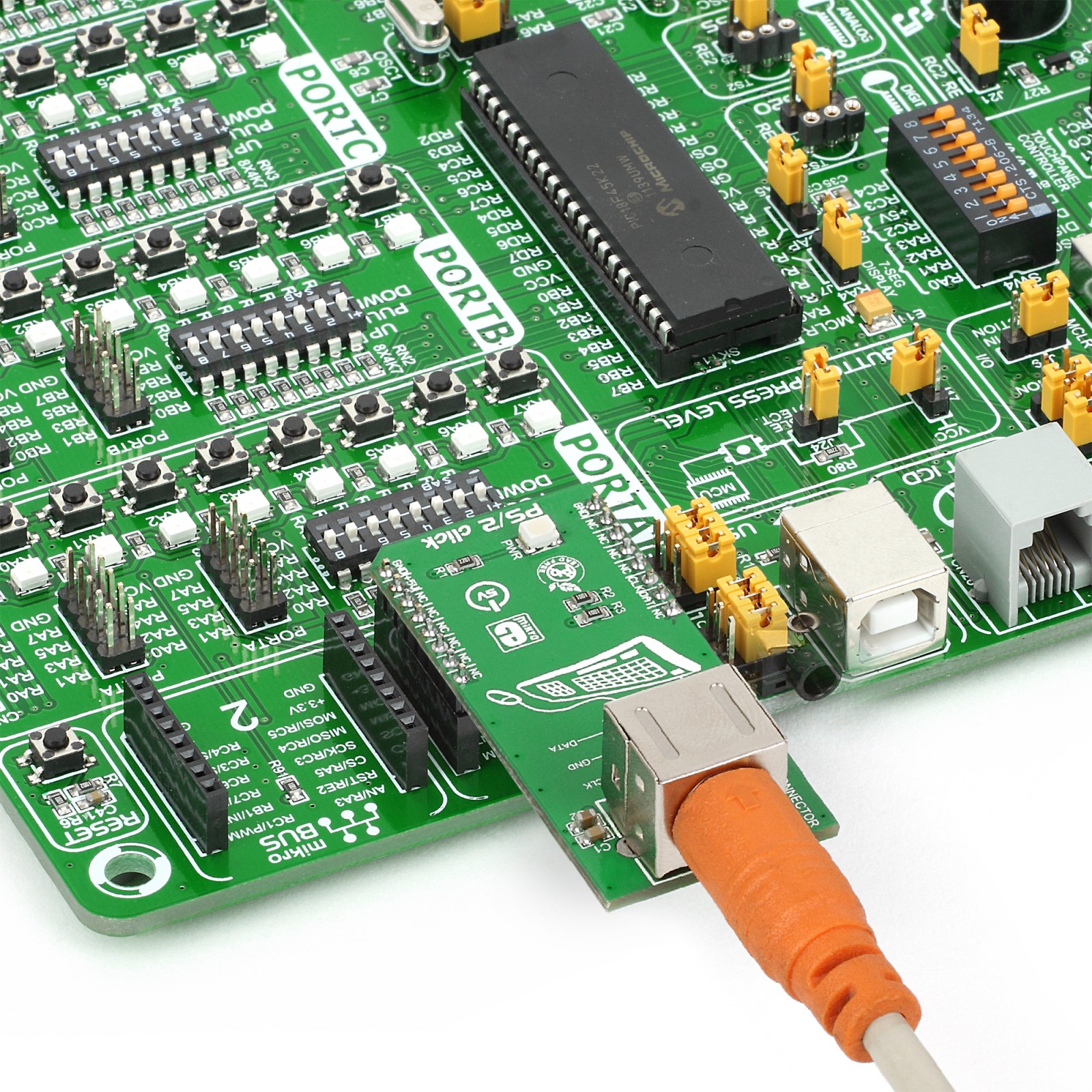
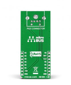
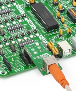
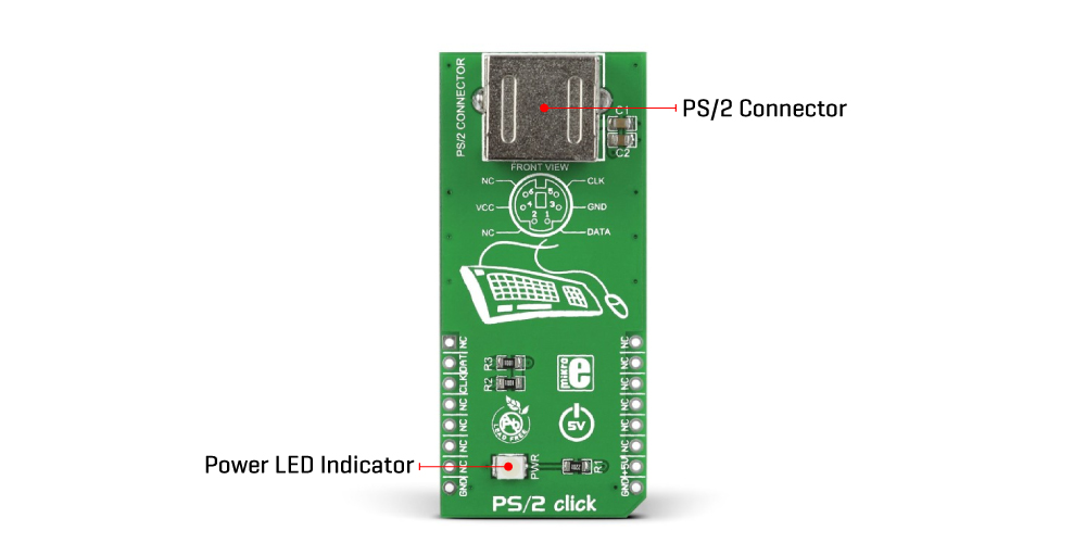
PS/2 Click is an adapter Click board™ based on the standard 6-pin Mini-DIN PS/2 connector. It is an alternative to the USB connector for modern peripherals and implements a bidirectional synchronous serial protocol. The PS/2 Click supports a standard PS/2 keyboard or a standard PS/2 mouse as a device, and it should be noted that it is not recommended to hot-plug any of the devices to the host microcontroller.
To communicate with the host microcontroller, this Click board™ uses the CLK, the SCLK or the clock line, and the DAT, the SDATA or data line. The PS/2 mouse and keyboard implement a bidirectional synchronous serial protocol. The bus is “Idle” when both lines are high (open-collector). The idle state is the only state where the keyboard/mouse is allowed to begin transmitting data. The host has ultimate control over the bus and may inhibit communication anytime by pulling the clock line low.
The PS/2 device generates all clock signals on the SCLK pin for both host-to-device and device-to-host transfers. During device-to-host transfers, the device controls both SCLK and SDATA. The device maintains a consistent SCLK cycle between 10kHz and 14.6kHz, updates SDATA while SCLK is high, and the host sample SDATA when SCLK is low. If the host wants to send data, it must first inhibit communication from the device by pulling the clock low. The host then pulls data low and releases the clock. This is the “Request-to-Send” state and signals the device to start generating clock pulses.
This Click board™ can only be operated with a 5V logic voltage level. The board must perform appropriate logic voltage level conversion before using MCUs with different logic levels. However, the Click board™ comes equipped with a library containing functions and an example code that can be used, as a reference, for further development.
Specifications
Type
Adapter
Applications
Can be used for connecting PS/2 keyboards and mouse to your target device
Key Features
5V power supply according to the PS/2 standard, supports both keyboards and mouse connection, two main signal lines: data and clock, not recommended to hot-plug, and more
Interface
GPIO
Feature
No ClickID
Compatibility
mikroBUS™
Click board size
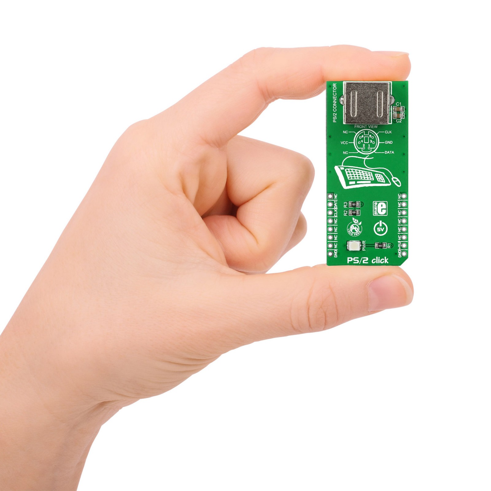
L (57.15 x 25.4 mm)
Input Voltage
5V
Pinout diagram
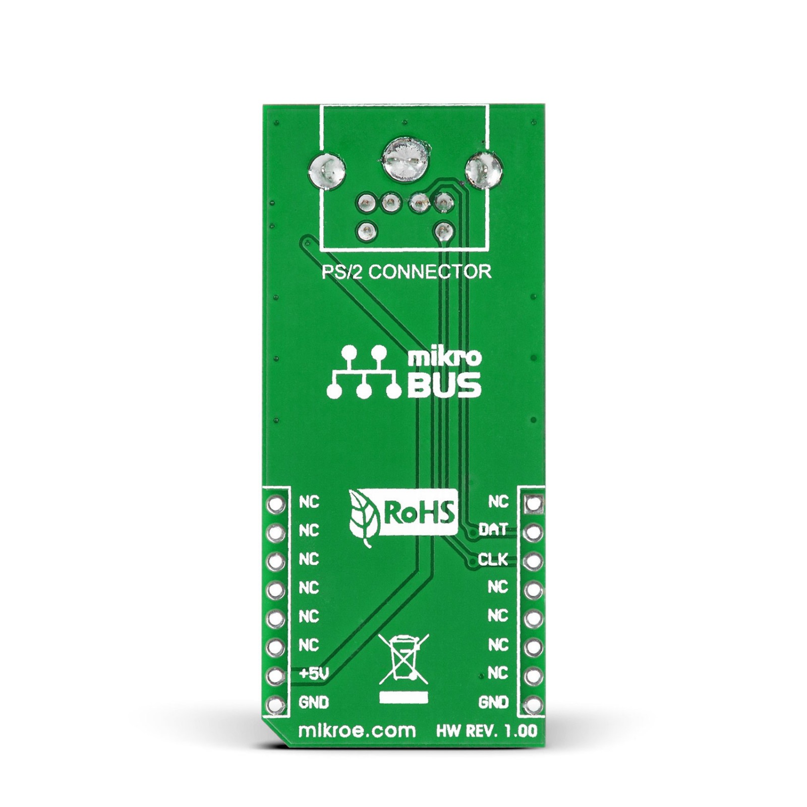
This table shows how the pinout on PS/2 Click corresponds to the pinout on the mikroBUS™ socket (the latter shown in the two middle columns).
Onboard settings and indicators
Label | Name | Default | Description |
---|---|---|---|
LD1 | PWR | – | Power LED Indicator |
PS/2 Click electrical specifications
Description | Min | Typ | Max | Unit |
---|---|---|---|---|
Supply Voltage | – | 5 | – | V |
Software Support
We provide a library for the PS 2 Click on our LibStock page, as well as a demo application (example), developed using MikroElektronika compilers. The demo can run on all the main MikroElektronika development boards.
Library Description
The library covers all the necessary functions to control PS/2 click board.
Key functions:
void ps2_gpioDriverInit(T_PS2_P gpioObj)
– Function initializes GPIO driver for the desired MIKROBUS1.
Examples description
The application is composed of three sections :
- System Initialization – Initializes GPIO and start to write log.
- Application Initialization – Initialization driver enables – GPIO, also display logs.
- Application Task – (code snippet) This is an example which demonstrates the use of PS/2 Click board. In this example, key(s) pressed on the PS/2 keyboard are read and transferred to the PC through serial port connection. Various basic keyboard activities are tested: “normal” keys, keys with pressed, keys with pressed, numerical keypad ON/OFF and keys. Results are being sent to the Usart Terminal where you can track their changes.
void applicationTask() { char logText; if ( Ps2_Key_Read( &logText, &specialFlag, &pressedState ) ) { if ( pressedState ) { if ( logText == _PS2_BACKSPACE ) { mikrobus_logWrite( " <- Backspace", _LOG_LINE ); } if ( logText == _PS2_ENTER ) { mikrobus_logWrite( "", _LOG_LINE ); } if ( !specialFlag && logText ) { mikrobus_logWrite( &logText, _LOG_BYTE ); } } } Delay_1ms(); }
The full application code, and ready to use projects can be found on our LibStock page.
Other mikroE Libraries used in the example:
- PS2
- UART
Additional notes and informations
Depending on the development board you are using, you may need USB UART click, USB UART 2 click or RS232 click to connect to your PC, for development systems with no UART to USB interface available on the board. The terminal available in all MikroElektronika compilers, or any other terminal application of your choice, can be used to read the message.
mikroSDK
This Click board™ is supported with mikroSDK – MikroElektronika Software Development Kit. To ensure proper operation of mikroSDK compliant Click board™ demo applications, mikroSDK should be downloaded from the LibStock and installed for the compiler you are using.
For more information about mikroSDK, visit the official page.