How does it work?
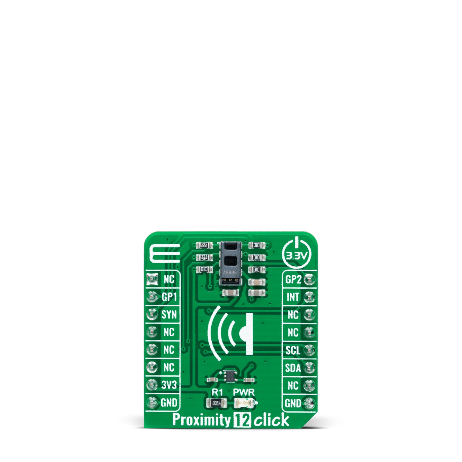
Proximity 12 Click as its foundation uses the TMD3719, an optical sensor that integrates ambient light sensing, proximity detection, and flicker detection sensing from AMS-AG. The ambient light and color sensing function provide six concurrent ambient light sensing channels: Red, Green, Blue, Clear, Leakage, and Wideband, which accurately measure ambient light and calculate illuminance, chromaticity, and color temperature. The TMD3719 also integrates direct detection of ambient light flicker for four selectable frequency bins, executed parallel with ambient light and color sensing.
The proximity function synchronizes IR emission and detection to sense nearby objects. This function features self-maximizing dynamic range, ambient light subtraction, and advanced cross-talk cancelation. The proximity engine recognizes detect/release events and produces a configurable interrupt, routed to the INT pin of the mikroBUS™ socket, whenever the proximity result crosses upper or lower threshold settings.
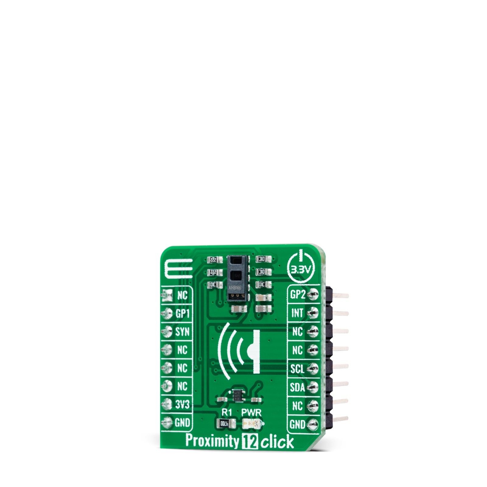
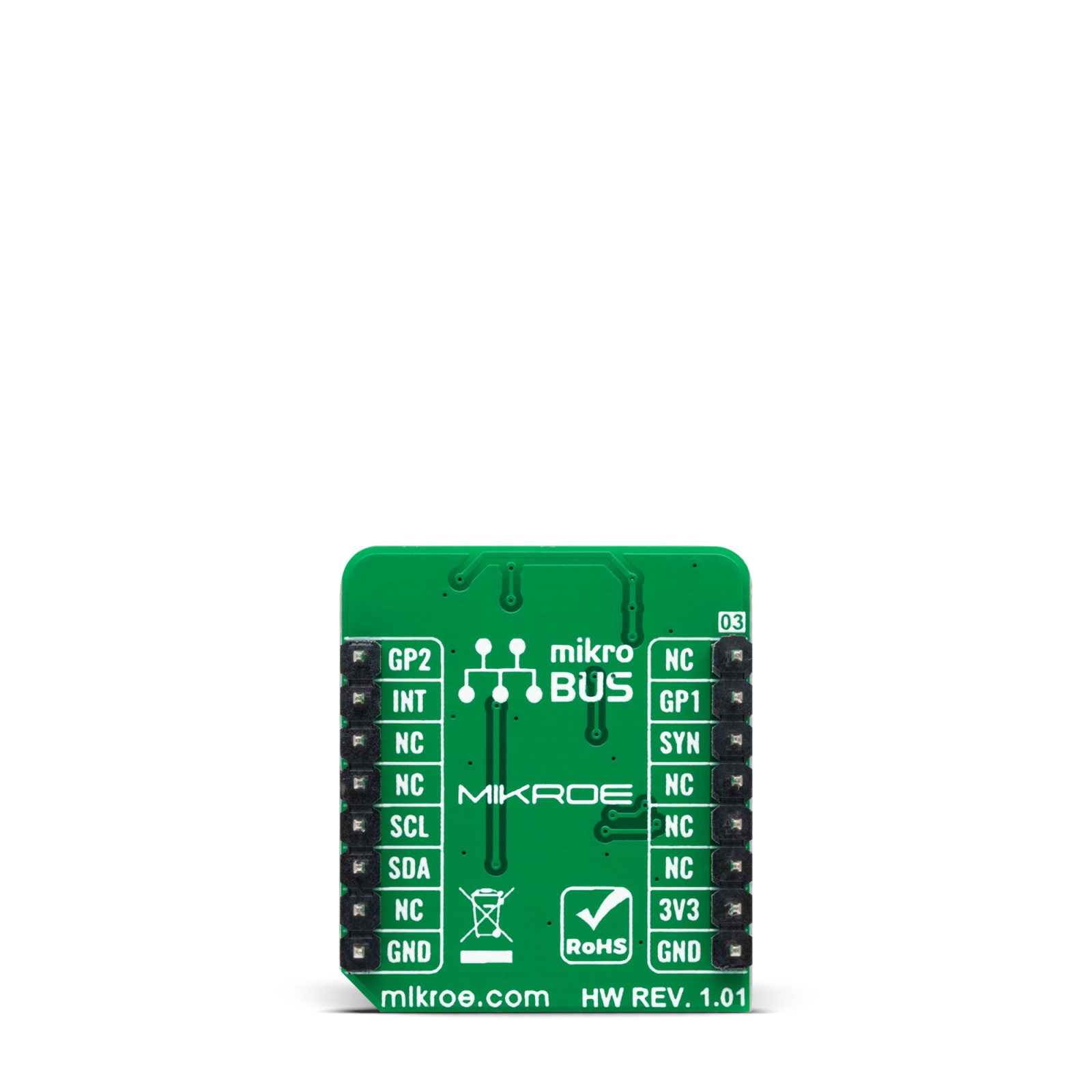
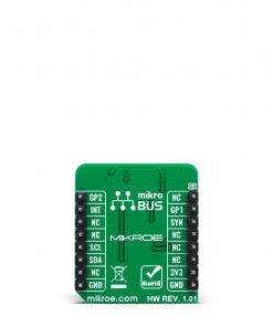
Proximity 12 Click communicates with MCU using the standard I2C 2-Wire interface with a maximum clock frequency of up to 400kHz. In addition to I2C communication, several GPIO pins connected to the mikroBUS™ socket pins are also used. The SYN pin, routed to the CS pin of the mikroBUS™ socket, is used to synchronize data and allows the start of the classic ambient light, proximity sensing, and flicker detection with every new SYN signal instead of immediately. It also has two pins labeled GP1 and GP2, routed on the RST and PWM pins of the mikroBUS™ socket, used as general-purpose pins, more precisely, GP1 as open-drain general purpose input/output and GP2 only as an input pin.
The TMD3719 requires a supply voltage of 1.8V to work correctly. Therefore, a small regulating LDO is used, the BH18PB1WHFV from Rohm Semiconductor, providing a 1.8V out of 3.3V mikroBUS™ rail. The LDO cut power consumption by lowering its current consumption to approximately 2μA when the application is operating in the Standby state.
This Click board™ can be operated only with a 3.3V logic voltage level. The board must perform appropriate logic voltage level conversion before use with MCUs with different logic levels. However, the Click board™ comes equipped with a library containing functions and an example code that can be used, as a reference, for further development.
Specifications
Type
Proximity
Applications
Can be used for consumer and industrial applications such as brightness and color management, flicker-immune operations, and many more
On-board modules
TMD3719, an optical sensor that integrates ambient light sensing, proximity detection, and flicker detection sensing from AMS-AG
Key Features
Low power consumption, synchronized proximity function, high sensitivity, improved lux accuracy, RGB sensing, flicker detection, and more
Interface
I2C
Feature
No ClickID
Compatibility
mikroBUS™
Click board size
S (28.6 x 25.4 mm)
Input Voltage
3.3V
Pinout diagram
This table shows how the pinout on Proximity 12 Click corresponds to the pinout on the mikroBUS™ socket (the latter shown in the two middle columns).
Onboard settings and indicators
Label | Name | Default | Description |
---|---|---|---|
LD1 | PWR | – | Power LED Indicator |
Proximity 12 Click electrical specifications
Description | Min | Typ | Max | Unit |
---|---|---|---|---|
Supply Voltage | – | 3.3 | – | V |
Operating Range | – | – | 20 | cm |
Peak Wavelenght | – | 940 | – | nm |
Operating Temperature Range | -30 | +25 | +85 | °C |
Software Support
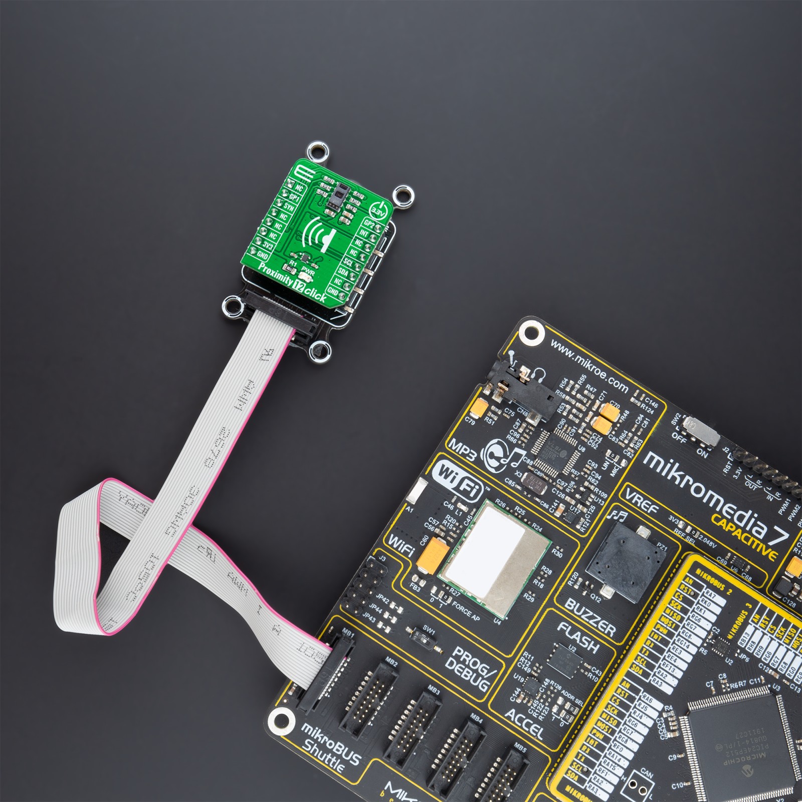
We provide a library for the Proximity 12 Click as well as a demo application (example), developed using MikroElektronika compilers. The demo can run on all the main MikroElektronika development boards.
Package can be downloaded/installed directly from NECTO Studio Package Manager(recommended way), downloaded from our LibStock™ or found on Mikroe github account.
Library Description
This library contains API for Proximity 12 Click driver.
Key functions:
proximity12_cfg_setup
– Config Object Initialization function.proximity12_init
– Initialization function.proximity12_default_cfg
– Click Default Configuration function.
Examples description
This function demonstrates the use of Proximity 12 click board.
void application_task ( void ) { uint16_t prox_data = 0; proximity12_als_data_t als; err_t error_flag = proximity12_read_proximity ( &proximity12, &prox_data ); error_flag |= proximity12_read_als ( &proximity12, &als ); if ( PROXIMITY12_OK == error_flag ) { log_printf( &logger, " - Proximity data -rn" ); log_printf( &logger, " Proximity: %urn", prox_data ); log_printf( &logger, " - ALS data -rn" ); log_printf( &logger, " Clear: %lu - Red: %lu - Green: %lu - Blue: %lurn", als.clear, als.red, als.green, als.blue ); log_printf( &logger, " Leakage: %lu - Wideband: %lu - IR1: %lu - IR2: %lurnrn", als.leakage, als.wideband, als.ir1, als.ir2 ); } Delay_ms( 100 ); }
The full application code, and ready to use projects can be installed directly from NECTO Studio Package Manager(recommended way), downloaded from our LibStock™ or found on Mikroe github account.
Other mikroE Libraries used in the example:
- MikroSDK.Board
- MikroSDK.Log
- Click.Proximity12
Additional notes and informations
Depending on the development board you are using, you may need USB UART click, USB UART 2 click or RS232 click to connect to your PC, for development systems with no UART to USB interface available on the board. The terminal available in all MikroElektronika compilers, or any other terminal application of your choice, can be used to read the message.
mikroSDK
This Click board™ is supported with mikroSDK – MikroElektronika Software Development Kit. To ensure proper operation of mikroSDK compliant Click board™ demo applications, mikroSDK should be downloaded from the LibStock and installed for the compiler you are using.
For more information about mikroSDK, visit the official page.