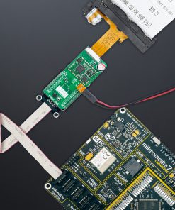
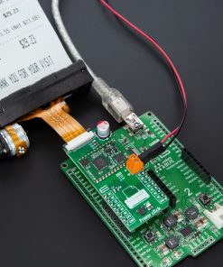
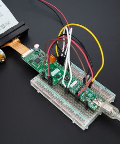
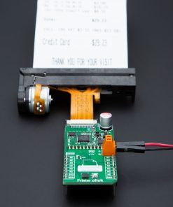
How does it work?
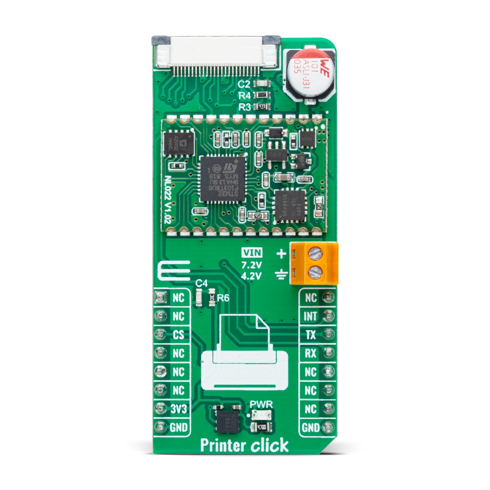
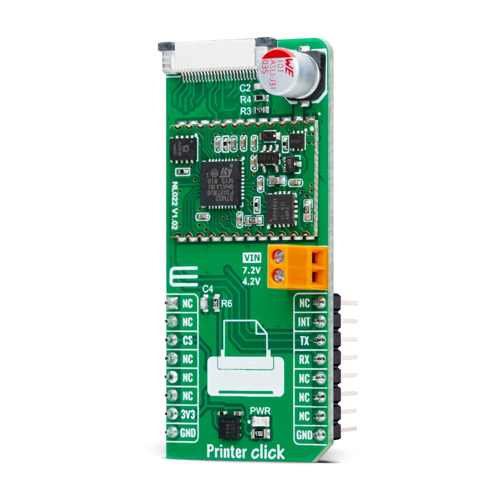
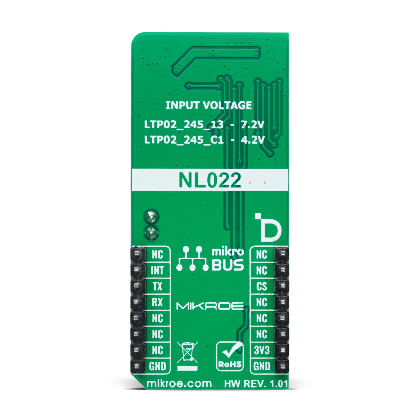
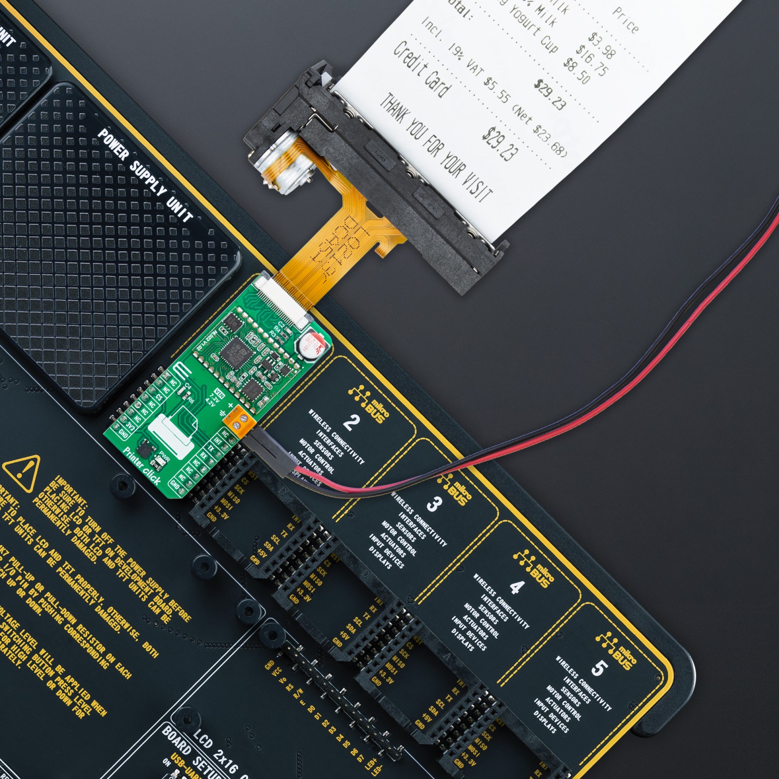
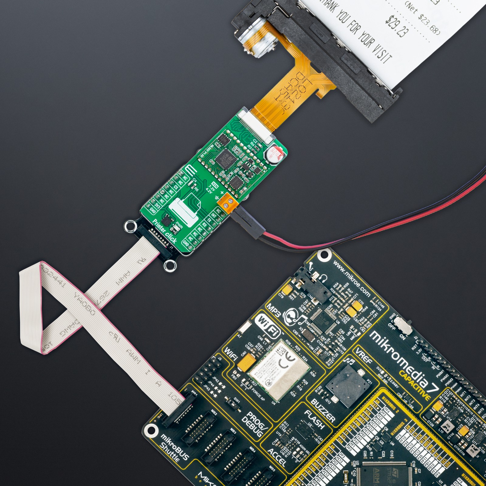
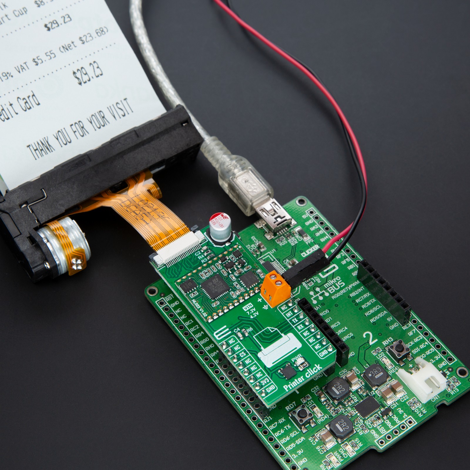
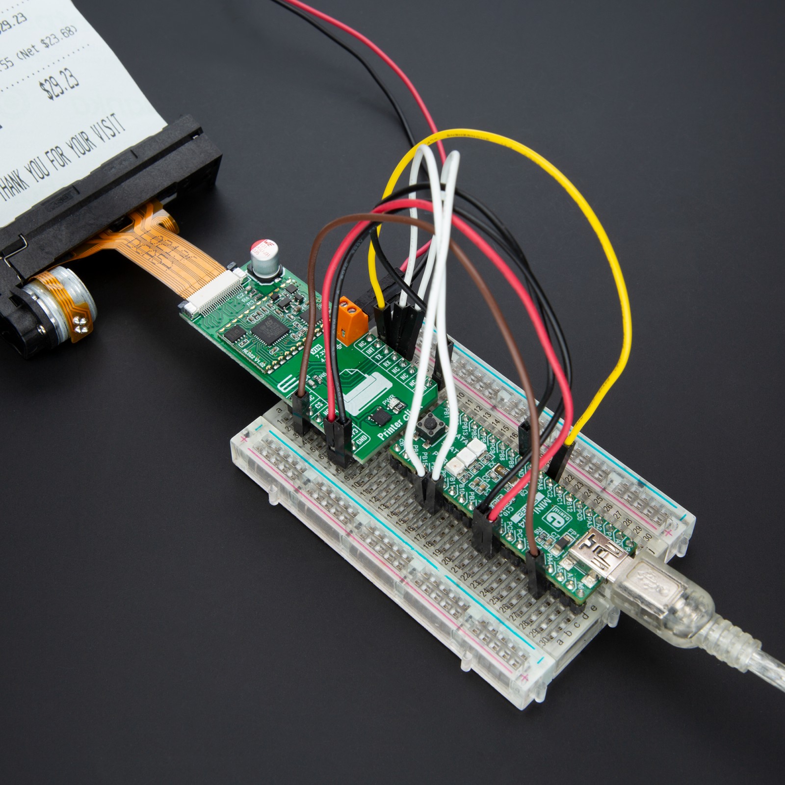
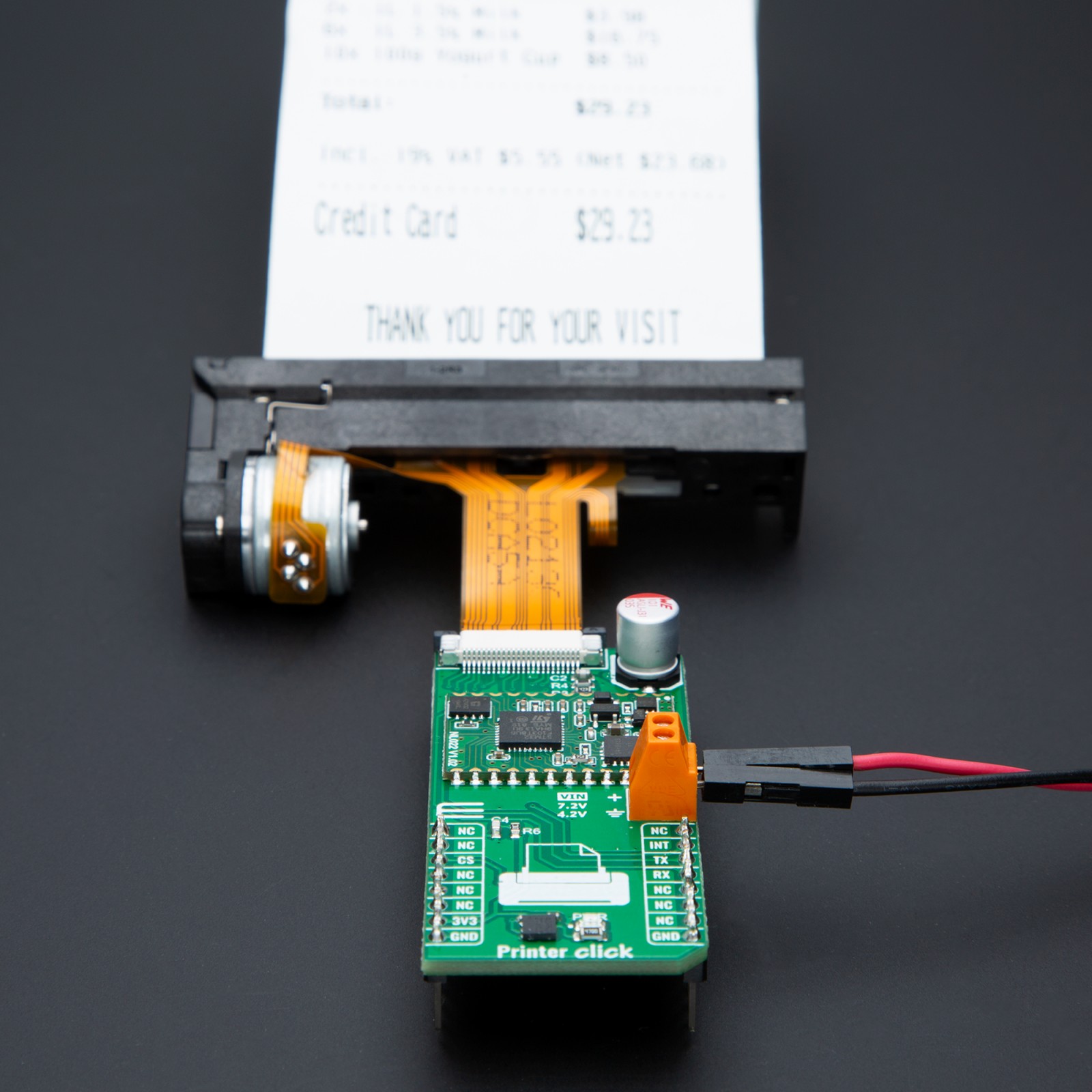
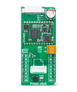
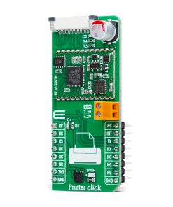
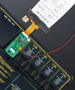
Printer Click is based on the NL022, a thermal printer head controller from Norden Logic designed for high-performance control of thermal printer heads, such as Seiko’s LTP02_245 series, including models like LTP02_245_13 with a 7.2V supply and LTP02_245_C1 with a 4.2V supply, but also LTP02-245-A, M23-DH-H69, JX-2R-17, TP2V MTP02, QJ02-245-13W, YAEN208, and M23-SX. The board receives power through the VIN terminal, which provides a stable and configurable input voltage to accommodate different thermal print heads, ensuring reliable operation across various supply requirements. This advanced controller communicates with the host MCU via the UART interface and adheres to the widely used ESC/POS programming standard, making it a highly adaptable solution for various printing applications, including medical devices, taxi meters, ticket machines, handheld POS terminals, industrial meters, and cash registers.
The NL022 excels due to its ARM-based architecture, offering vast RAM and Flash memory, real-time head temperature monitoring, and a responsive paper-out detection system. It supports user-definable flash storage and incorporates an extensive selection of built-in language fonts covering 170 languages, including UTF-8 and UTF-16 character encoding, as well as Chinese and Japanese script support. Custom font management and compatibility with ESC commands allow users to tailor text and print output to specific requirements.
NOTE: It is highly recommended to verify that your module is running firmware version 1.22. If it is not, you will need to upgrade the firmware to version 1.22 to ensure improved functionality and access to newly supported printer heads. For detailed documentation and the latest updates regarding firmware releases, please visit the Norden Logic support page.
The NL022 also supports a wide range of font attributes such as double width, double height, bold, italic, reverse, underline, and normal styles, ensuring customizable print output. It enables seamless 1D barcode printing, including formats like UPC-A, UPC-E, EAN-13, EAN-8, CODE39, CODE93, ITF25, CODABAR, and CODE128-A, while 2D barcodes, such as QR codes, can be generated directly on-chip using ESC commands. Additionally, the NL022 integrates essential real-time monitoring functionalities, including an overheat monitor for thermal head protection, a paper-out detection system to prevent printing errors, and a platen-out monitor for smooth operation.
As previously mentioned, this board communicates with the host MCU through the UART interface, using the TX and RX pins with a default baud rate of 115200bps for efficient data exchange. In addition to interface pins, the board also uses the INT pin, which functions as a ready-to-send signal. When the INT pin is in a LOW state, the NL022 controller is ready to receive and process data, whereas a HIGH state indicates that the controller is busy and cannot accept new data at that moment.
This Click board™ can be operated only with a 3.3V logic voltage level. The board must perform appropriate logic voltage level conversion before using MCUs with different logic levels. It also comes equipped with a library containing functions and example code that can be used as a reference for further development.
Specifications
Type
Printer
Applications
Ideal for applications such as medical devices, taxi meters, ticket machines, handheld POS terminals, industrial meters, and cash registers
On-board modules
NL022 – thermal printer head controller from Norden Logic
Key Features
Supported printer heads with various voltage ratings and diverse flat cable widths, 24-pin MOLEX connector, UART interface, ready-to-send signal, font and barcode (1D and 2D) support, overheat monitor, paper-out detection, platen-out detection, 170 languages including UTF-8, UTF-16, Chinese, and Japanese scripts, and more
Interface
UART
Feature
ClickID
Compatibility
mikroBUS™
Click board size
L (57.15 x 25.4 mm)
Input Voltage
3.3V,External
Pinout diagram
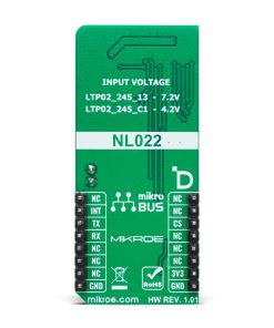
This table shows how the pinout on Printer Click corresponds to the pinout on the mikroBUS™ socket (the latter shown in the two middle columns).
Onboard settings and indicators
Label | Name | Default | Description |
---|---|---|---|
LD1 | PWR | – | Power LED Indicator |
Printer Click electrical specifications
Description | Min | Typ | Max | Unit |
---|---|---|---|---|
Supply Voltage | – | 3.3 | – | V |
Printer Head External Power Supply | 4.2 / 7.2 | V |
Software Support
Printer Click demo application is developed using the NECTO Studio, ensuring compatibility with mikroSDK‘s open-source libraries and tools. Designed for plug-and-play implementation and testing, the demo is fully compatible with all development, starter, and mikromedia boards featuring a mikroBUS™ socket.
Example Description
This example demonstrates the use of Printer Click board by providing user interaction with a thermal printer, allowing the user to check paper status, display commands, and execute various printing tasks based on user commands through a UART interface.
Key Functions
printer_cfg_setup
Config Object Initialization function.printer_init
Initialization function.printer_default_cfg
Click Default Configuration function.printer_get_status
This function reads the paper status and temperature of the printer and stores results in ctx->status string buffer.printer_get_fw_info
This function reads the firmware information of the printer and stores results in ctx->fw_info string buffer.printer_print_string_lf
This function prints a string message with line feed.
Application Init
Initializes the driver, performs the Click default configuration, and displays the list of supported commands on the USB UART.
Application Task
Checks the paper status and processes user commands.
Application Output
This Click board can be interfaced and monitored in two ways:
- Application Output - Use the “Application Output” window in Debug mode for real-time data monitoring. Set it up properly by following this tutorial.
- UART Terminal - Monitor data via the UART Terminal using a USB to UART converter. For detailed instructions, check out this tutorial.
Additional Notes and Information
The complete application code and a ready-to-use project are available through the NECTO Studio Package Manager for direct installation in the NECTO Studio. The application code can also be found on the MIKROE GitHub account.