Power Step 2 Click
R1,000.00 ex. VAT
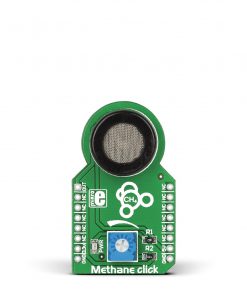
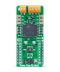
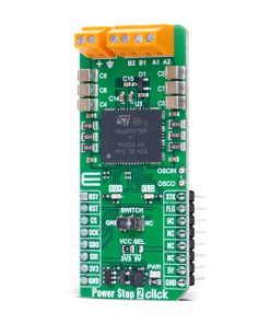
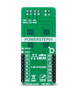
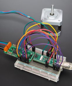
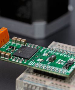
Power Step 2 Click is a compact add-on board for precise motion control applications. It is based on the powerSTEP01, a powerful 1/128 microstepping controller from STMicroelectronics, that integrates eight N-channel MOSFETs with ultra-low RDS(on). This board operates at voltages up to 85V, delivering up to 10A RMS output current while supporting both voltage mode driving and advanced current control. It features a high-speed 5MHz SPI interface, multiple safety protections, and additional control pins for enhanced functionality, including step clock input and motor initialization. The board also provides LED indicators for quick status monitoring and supports external clock synchronization. With its robust design and precise microstepping capabilities, Power Step 2 Click is ideal for industrial automation, medical equipment, robotics, antenna positioning, CCTV and security systems, and dome cameras.
Power Step 2 Click is fully compatible with the mikroBUS™ socket and can be used on any host system supporting the mikroBUS™ standard. It comes with the mikroSDK open-source libraries, offering unparalleled flexibility for evaluation and customization. What sets this Click board™ apart is the groundbreaking ClickID feature, enabling your host system to seamlessly and automatically detect and identify this add-on board.
Stock: Lead-time applicable.
| 5+ | R950.00 |
| 10+ | R900.00 |
| 15+ | R850.00 |
| 20+ | R818.00 |
How does it work?
Power Step 2 Click is based on the powerSTEP01, an a power 1/128 microstepping controller from STMicroelectronics. This system-in-package solution integrates eight N-channel MOSFETs with an ultra-low RDS(on) of just 16mΩ, enabling precise control of stepper motors operating at voltages up to 85V while delivering a maximum output current of 10A RMS. The board is designed to offer full digital motion control, using an SPI-programmable interface for speed profile generation and accurate positioning. With its powerful combination of high voltage handling, precise microstepping control, and an extensive safety feature set, the Power Step 2 Click is an ideal solution for applications requiring precise motor control, including industrial process automation, medical analysis equipment, robotics, antenna positioning, CCTV and security systems, and dome camera mechanisms.

At the core of the powerSTEP01 is its capability to support both voltage mode driving and advanced current control, making it adaptable to a variety of motor control applications. With its embedded dual full-bridge configuration and non-dissipative overcurrent protection, it ensures reliability even in demanding environments. The digital control engine allows users to define custom motion profiles, including acceleration, deceleration, speed, and target positioning, all of which can be conveniently programmed through a dedicated register set via the high-speed 5MHz SPI interface. Safety and robustness are key aspects of the powerSTEP01 architecture. It includes a comprehensive set of protection features such as thermal shutdown, low bus voltage detection, overcurrent protection, and motor stall detection, ensuring uninterrupted and secure operation under all conditions.
In addition to the SPI interface pins, Power Step 2 Click uses several additional control pins for enhanced functionality. The RST pin serves as both a standby and reset control, where pulling it to a LOW logic level places the device in standby mode and resets its logic. The STK pin acts as the step clock input, allowing precise motor motion control in step-clock mode. Each rising edge of the step-clock signal applied to this pin advances the motor by one microstep in the programmed direction while simultaneously updating the absolute position. Furthermore, the board features a SWITCH, which plays a crucial role in motor initialization. Since the initial position of the stepper motor is often undefined at power-up, an initialization sequence is required to move it to a known position. The GoUntil and ReleaseSW commands, in conjunction with this switch, makes a straightforward method for setting the motor’s reference position.
This Click board™ also includes two important status pins for monitoring device operation. The FLG pin serves as a status flag output whenever a programmed alarm condition is triggered. These conditions may include step loss, overcurrent detection (OCD), thermal pre-warning or shutdown, undervoltage lockout (UVLO), invalid commands, or non-performable commands. The BSY pin, on the other hand, is primarily used to indicate when the device is actively executing a command by default. However, it can also be configured to generate a synchronization signal if required. Both of these signals are accompanied by dedicated LED indicators – a red LED for FLG and a yellow LED for BSY – providing clear visual feedback for quick status monitoring and troubleshooting.
The Power Step 2 Click also includes two unpopulated pins, OSCIN and OSCO, which allow for the connection of an external oscillator or clock source. When an external clock is not used, the internal oscillator provides a configurable clock signal through the OSCO pin, which can output frequencies of 2MHz, 4MHz, 8MHz, or 16MHz, depending on the selected settings. This flexibility enables users to synchronize the motor driver with other system components or optimize performance based on specific application requirements.
This Click board™ can operate with either 3.3V or 5V logic voltage levels selected via the VCC SEL jumper. This way, both 3.3V and 5V capable MCUs can use the communication lines properly. Also, this Click board™ comes equipped with a library containing easy-to-use functions and an example code that can be used as a reference for further development.
Specifications
Type
Stepper
Applications
Ideal for industrial automation, medical equipment, robotics, antenna positioning, CCTV and security systems, and dome cameras
On-board modules
powerSTEP01 – power 1/128 microstepping controller from STMicroelectronics
Key Features
Stepper motor driver with 1/128 microstepping resolution, integrated eight N-channel MOSFETs with ultra-low RDS(on), supports both voltage mode driving and advanced current control, SPI-programmable interface, dual full-bridge architecture with non-dissipative overcurrent protection, safety features, additional control pins for step clock input, standby/reset, and motor initialization, and more
Interface
SPI
Feature
ClickID
Compatibility
mikroBUS™
Click board size
L (57.15 x 25.4 mm)
Input Voltage
3.3V or 5V,External
Pinout diagram
This table shows how the pinout on Power Step 2 Click corresponds to the pinout on the mikroBUS™ socket (the latter shown in the two middle columns).
| Notes | Pin | Pin | Notes | ||||
|---|---|---|---|---|---|---|---|
| Busy Status / Synchronization | BSY | 1 | AN | PWM | 16 | STK | Step-Clock Signal |
| Reset / ID SEL | RST | 2 | RST | INT | 15 | FLG | Fault Indicator |
| SPI Select / ID COMM | CS | 3 | CS | RX | 14 | NC | |
| SPI Clock | SCK | 4 | SCK | TX | 13 | NC | |
| SPI Data OUT | SDO | 5 | MISO | SCL | 12 | NC | |
| SPI Data IN | SDI | 6 | MOSI | SDA | 11 | NC | |
| Power Supply | 3.3V | 7 | 3.3V | 5V | 10 | 5V | Power Supply |
| Ground | GND | 8 | GND | GND | 9 | GND | Ground |
Onboard settings and indicators
| Label | Name | Default | Description |
|---|---|---|---|
| LD1 | PWR | – | Power LED Indicator |
| LD2 | FLG | – | Fault LED Indicator |
| LD3 | BSY | – | Busy Flag / Synchronization LED Indicator |
| JP1 | VCC SEL | Left | Power Voltage Level Selection 3V3/5V: Left position 3V3, Right position 5V |
| SW1 | SWITCH | Left | Motor Position Initialization Switch |
Power Step 2 Click electrical specifications
| Description | Min | Typ | Max | Unit |
|---|---|---|---|---|
| Supply Voltage | 3.3 | – | 5 | V |
| External Power Supply | 7.5 | – | 85 | V |
| Output Current (RMS) | – | – | 10 | A |
Software Support
Power Step 2 Click demo application is developed using the NECTO Studio, ensuring compatibility with mikroSDK‘s open-source libraries and tools. Designed for plug-and-play implementation and testing, the demo is fully compatible with all development, starter, and mikromedia boards featuring a mikroBUS™ socket.
Example Description
This example demonstrates the use of the Power Step 2 Click board for precise control of stepper motors. The application showcases various step modes, directions, and speeds while demonstrating the board’s ability to control motors using different operation modes.
Key Functions
powerstep2_cfg_setupConfig Object Initialization function.powerstep2_initInitialization function.powerstep2_default_cfgClick Default Configuration function.powerstep2_set_step_modeThis function sets the step mode (microstepping level) of the Power Step 2 device.powerstep2_set_speedThis function sets the minimum and maximum speeds for motor movement.powerstep2_moveThis function moves the motor a specified number of steps in a given direction.
Application Init
Initializes the logger and configures the Power Step 2 Click board. The default settings are applied to prepare the device for motor control operations.
Application Task
Demonstrates motor control with various configurations. The example alternates between multiple step modes (1/8, 1/16, 1/32, 1/4), directions (CW, CCW), speeds, and control modes (voltage, current). Each configuration is applied sequentially, with the motor driven through specified steps before switching to the next configuration.
Application Output
This Click board can be interfaced and monitored in two ways:
- Application Output – Use the “Application Output” window in Debug mode for real-time data monitoring. Set it up properly by following this tutorial.
- UART Terminal – Monitor data via the UART Terminal using a USB to UART converter. For detailed instructions, check out this tutorial.
Additional Notes and Information
The complete application code and a ready-to-use project are available through the NECTO Studio Package Manager for direct installation in the NECTO Studio. The application code can also be found on the MIKROE GitHub account.
Resources
Downloads
| Weight | 22 g |
|---|---|
| Brand | MikroElektronika |