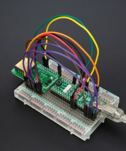
How does it work?
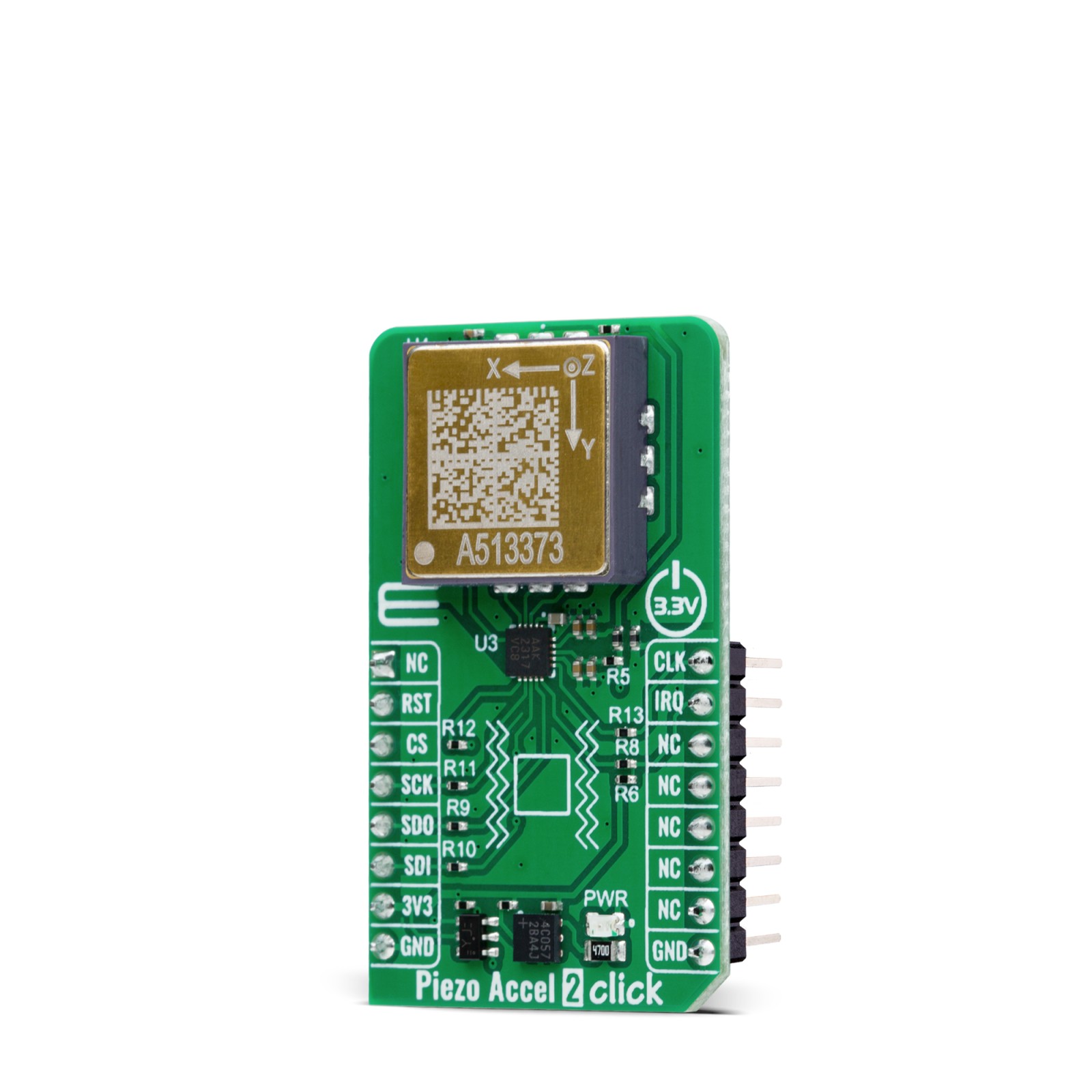
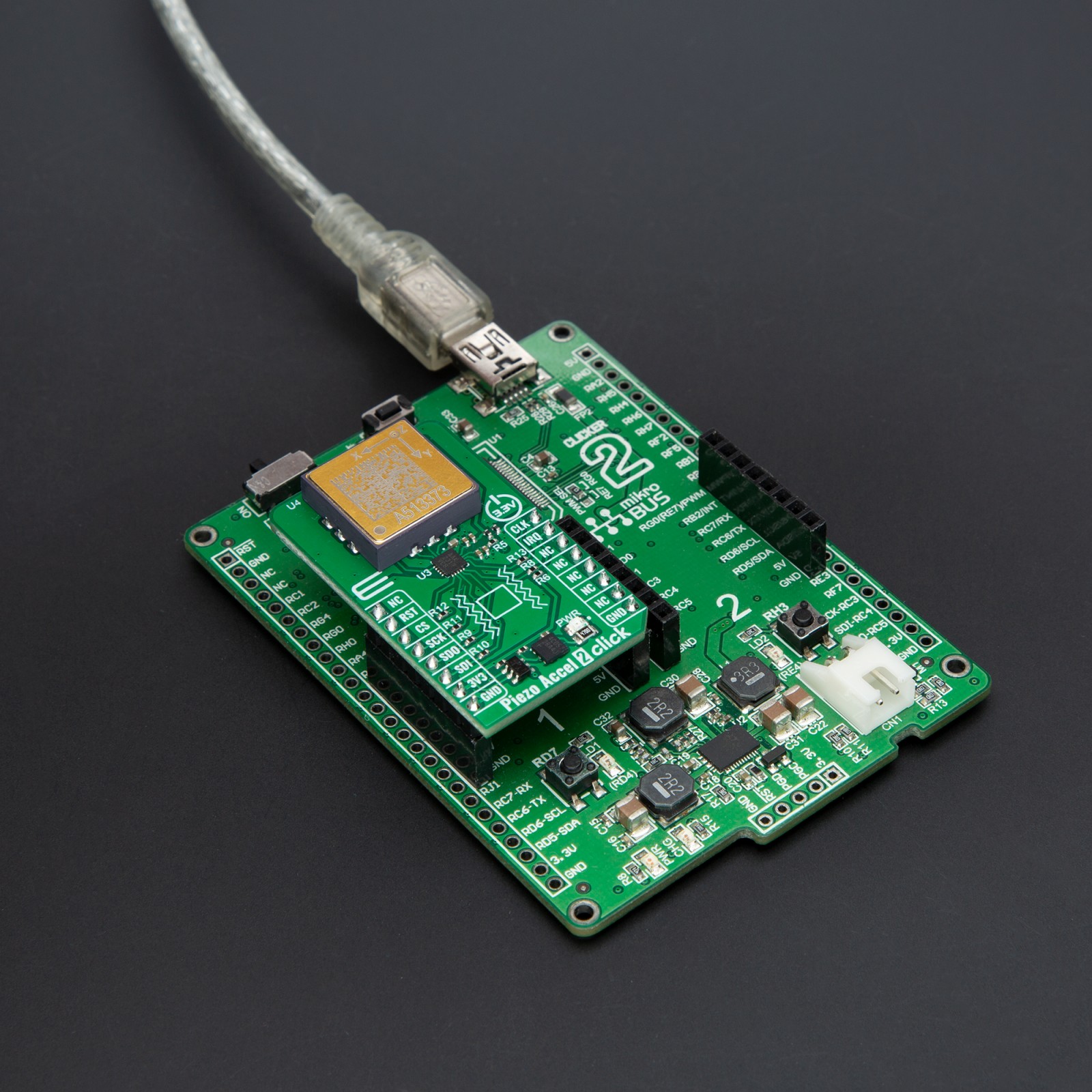
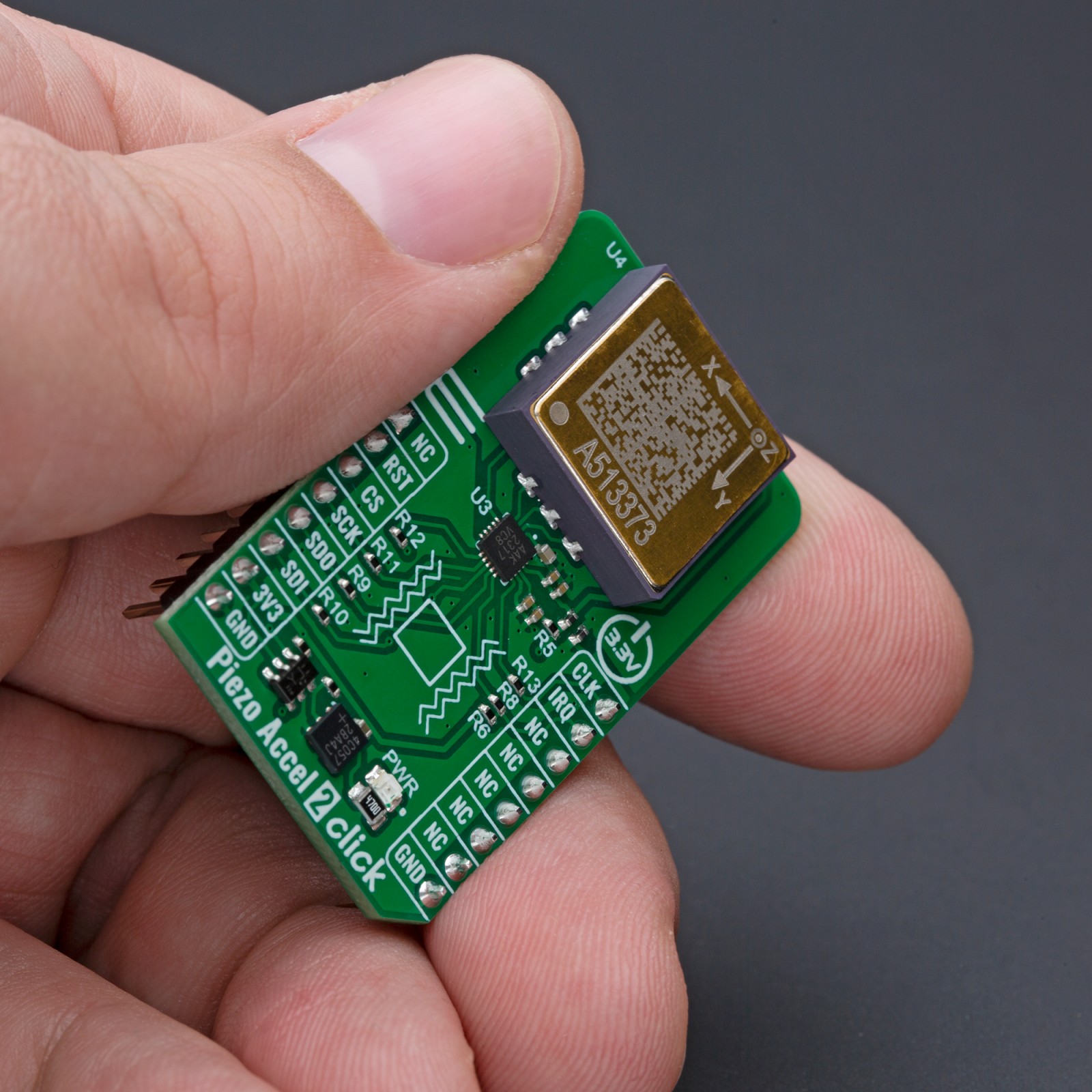
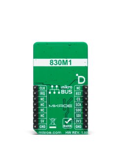
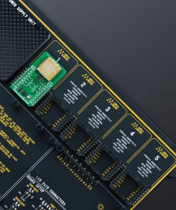
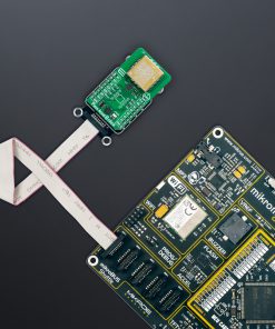
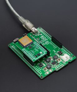
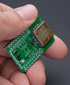
Piezo Accel 2 Click – 50g is based on the 830M1-0050, a triaxial piezoelectric accelerometer from TE Connectivity, capable of detecting motion and acceleration along all three orthogonal axes (X, Y, Z). The 830M1-0050 provides accurate and stable motion and acceleration measurements. It offers analog voltage outputs proportional to the magnitude of acceleration along the X, Y, and Z axes, with a range of ±50g and a sensitivity of 25mV/g. This sensor leverages proven piezoelectric technology for exceptional resolution, dynamic range, and bandwidth, outperforming traditional MEMS devices in demanding environments. Additionally, it features an integrated RTD temperature sensor, enabling simultaneous vibration and temperature data acquisition for comprehensive condition monitoring. Its high sensitivity, reliable performance, and compatibility with embedded systems make it ideal for applications like machine health monitoring, predictive maintenance, impact and shock monitoring, and security systems.
Piezo Accel 2 Click communicates with a host MCU through the onboard MCP3562R, a 24-bit low-noise delta-sigma Analog-to-Digital Converter (ADC). This ADC digitizes the analog outputs from the 830M1-0050 sensor, providing high-resolution data with a programmable data rate of up to 153.6kSPS. The MCP3562R features an internal voltage reference, oscillator, temperature sensor, and burnout sensor detection, further enhancing its functionality. Communication with the host MCU is made via the SPI interface, operating at a maximum frequency of 20MHz.
In addition to the SPI communication pins, the MCP3562R also uses CLK and IRQ pins. The CLK pin functions as either a master clock input or an analog master clock output, depending on the configuration of the ADC’s CONFIG register. This clock is distinct from the SPI clock and is essential for continuous ADC operation during signal conversion. The IRQ pin serves as an interrupt output for various ADC events, such as conversion start, data readiness, power-on reset (POR), and CRC errors in the register map configuration. Furthermore, this pin can also function as a modulator data output, providing synchronized output with the analog master clock.
This Click board™ can be operated only with a 3.3V logic voltage level. The board must perform appropriate logic voltage level conversion before using MCUs with different logic levels. Also, it comes equipped with a library containing functions and an example code that can be used as a reference for further development.
Specifications
Type
Motion
Applications
Ideal for applications like machine health monitoring, predictive maintenance, impact and shock monitoring, and security systems
On-board modules
830M1-0050 – triaxial piezoelectric accelerometer from TE Connectivity
Key Features
±50g with a sensitivity of 25mV/g, integrated RTD temperature sensor for simultaneous vibration and temperature monitoring, ADC converter with SPI interface for connection with the host MCU, pin for master clock input/output and interrupt/modulator data output, and more
Interface
SPI
Feature
ClickID
Compatibility
mikroBUS™
Click board size
M (42.9 x 25.4 mm)
Input Voltage
3.3V
Pinout diagram
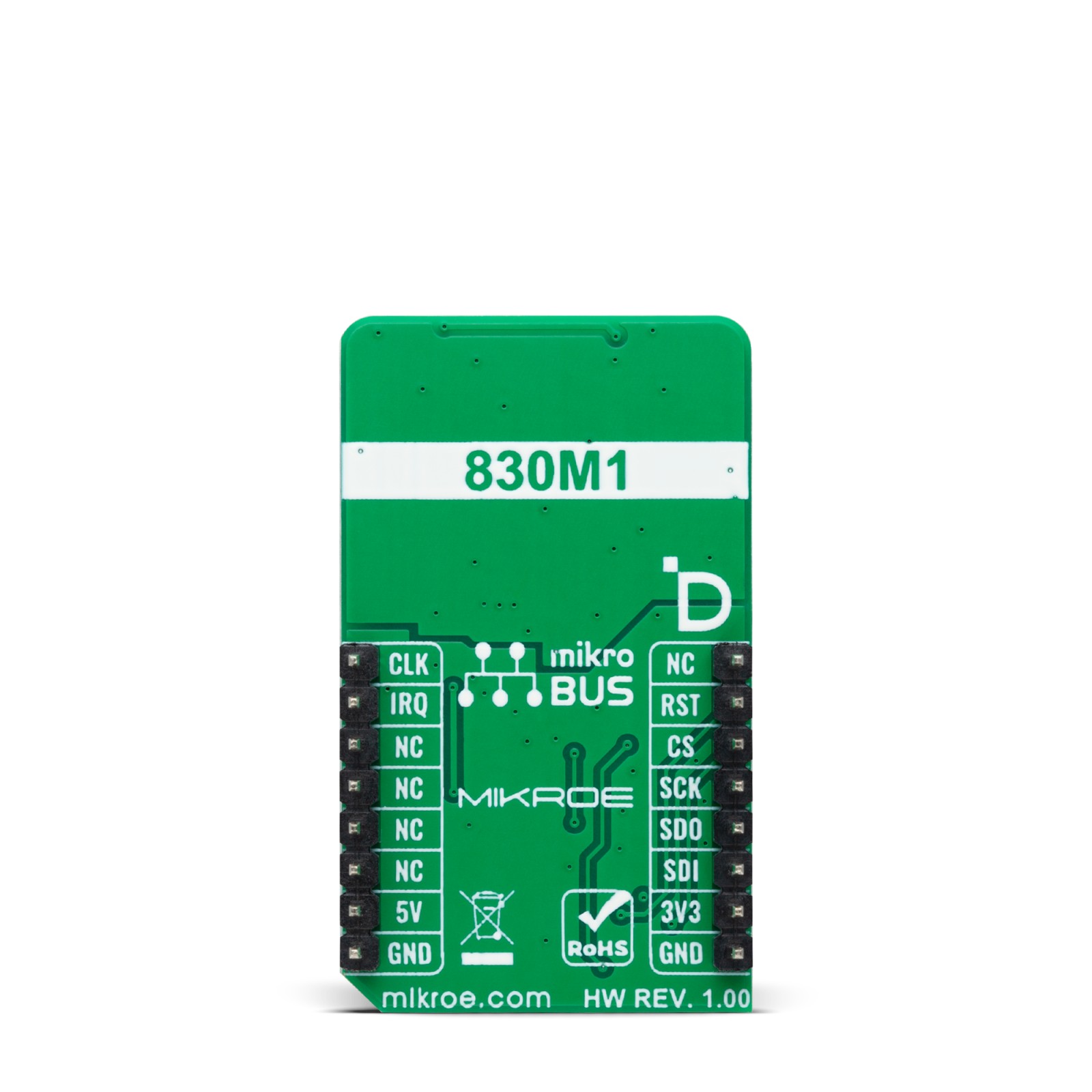
This table shows how the pinout on Piezo Accel 2 Click corresponds to the pinout on the mikroBUS™ socket (the latter shown in the two middle columns).
Onboard settings and indicators
Label | Name | Default | Description |
---|---|---|---|
LD1 | PWR | – | Power LED Indicator |
Piezo Accel 2 Click electrical specifications
Description | Min | Typ | Max | Unit |
---|---|---|---|---|
Supply Voltage | – | 3.3 | – | V |
Measurement Range | -50 | – | +50 | g |
Sensitivity | – | 25 | – | mV/g |
Software Support
We provide a library for the Piezo Accel 2 Click as well as a demo application (example), developed using MIKROE compilers. The demo can run on all the main MIKROE development boards.
Package can be downloaded/installed directly from NECTO Studio Package Manager (recommended), downloaded from our LibStock™ or found on MIKROE github account.
Library Description
This library contains API for Piezo Accel 2 Click driver.
Key functions
-
piezoaccel2_read_adc_data
This function reads raw ADC values of X, Y, and Z axis, and the internal temperature sensor measurements. -
piezoaccel2_fast_cmd_write
This function writes the selected fast command by using SPI serial interface. -
piezoaccel2_reg_read_multi
This function reads a desired number of data bytes starting from the selected register by using SPI serial interface.
Example Description
This example demonstrates the use of Piezo Accel 2 Click by reading and displaying the ADC values of X, Y, and Z axis, and the internal temperature sensor measurements.
Those data can be visualized on the SerialPlot application.
void application_task ( void )
{
piezoaccel2_adc_data_t adc_data;
if ( PIEZOACCEL2_OK == piezoaccel2_read_adc_data ( &piezoaccel2, &adc_data ) )
{
log_printf ( &logger, "%lu;%lu;%lu;%lu;rn", adc_data.raw_x, adc_data.raw_y,
adc_data.raw_z, adc_data.raw_temp );
}
}
The full application code, and ready to use projects can be installed directly from NECTO Studio Package Manager (recommended), downloaded from our LibStock™ or found on MIKROE github account.
Other MIKROE Libraries used in the example:
- MikroSDK.Board
- MikroSDK.Log
- Click.PiezoAccel2
Additional notes and informations
Depending on the development board you are using, you may need USB UART click, USB UART 2 Click or RS232 Click to connect to your PC, for development systems with no UART to USB interface available on the board. UART terminal is available in all MIKROE compilers.
mikroSDK
This Click board™ is supported with mikroSDK – MIKROE Software Development Kit. To ensure proper operation of mikroSDK compliant Click board™ demo applications, mikroSDK should be downloaded from the LibStock and installed for the compiler you are using.
For more information about mikroSDK, visit the official page.