USB connector
The USB-B port can be used to access the onboard programmer and ICD debugger.

mikroICD and programmer
Onboard fast USB 2.0 programmer and in-circuit debugger for testing and debugging programs on PIC devices.

Power Supply
The USB-B port can be used to access the onboard programmer and ICD debugger.

Optocoupler connectors
Screw terminals for optocouplers. All optocouplers are also linked to one common OCVCC connector.

Fast optocouplers
HP2630 optocouplers with Schmitt trigger galvanically isolate high-voltage signals brought to the MCU inputs.

Microphone
Screw terminals for connecting a microphone to the GSM module.

Speaker
Screw terminals for connecting speakers to the GSM module.

RS485
These enables the system to be connected to 485 network.

RS_232
MAX202C IC handles RS-232 communications with a PC or MCU.

GSM/GPRS connector
Used for connecting Telit’s GL865-QUAD GSM module via GSM booster card.

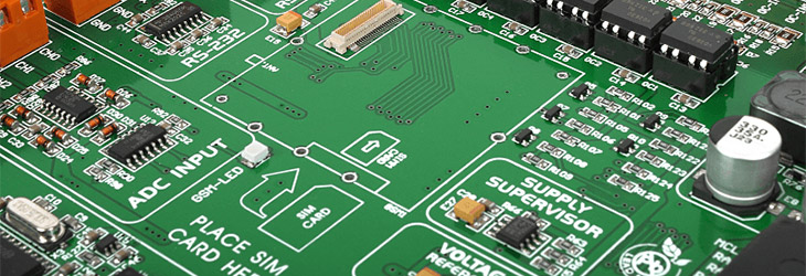
ADC
A/D converter MCP3204 is used for precise analog input measurement.

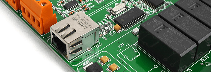
Ethernet connector
Serial ethernet communications are established through this port.

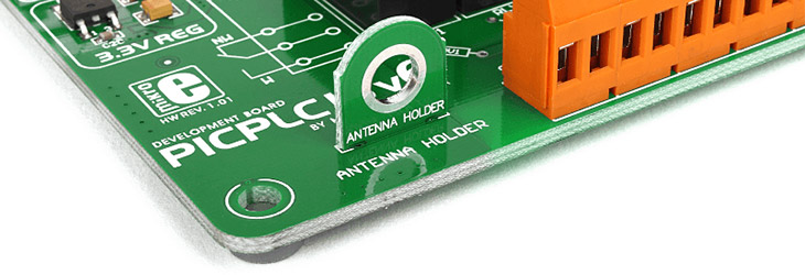
3.3V Voltage regulator
Used to provide a stable power supply to the serial ethernet module.

ENC28J60
A 28-pin, 10BASE-T stand-alone Ethernet Controller with SPI interface.

Antenna holder
This antenna holder is for fixing the external antenna from the GSM module (if it’s connected).

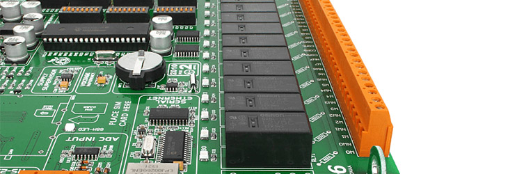
Relay Screw Terminal
There are 20 screw terminals. 16 for each relay, and four additional contacts—COMA, COMB, COMC and COMD—for connecting a group of four relays to a single contact.

16 Relays
Each relay has a LED for optical signalization and is designed for currents of up to 16 amps.

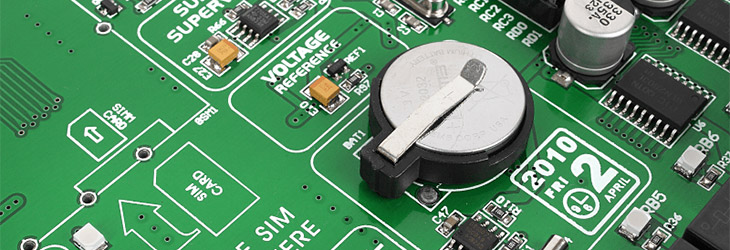
Real-time clock (RTC)
DS1307 with a battery supply keeps track of time, including weekdays, dates, and leap year corrections.

Voltage reference
Voltage reference for ADC can be either VCC (5V) or 4.096V.

Supply Supervisor
TL7700A is a supply voltage supervisor IC that functions as a reset controller.

PIC18F4520
The default MCU controlling PICPLC16 v6. Replacable with other 8-bit PICs in DIP-40 packaging.

Onboard jumpers
These jumpers are used for pull-up/pull-down configuration of each of the four ports.

IDC10 connectors
All pins are connected to IDC10 connectors, you can use them for further expansion and connectivity.

DIP switch
Use these switches to easily separate port pins from pull-up/pull-down resistors.