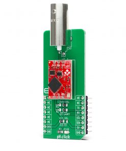
pH Click
R1,850.00 ex. VAT
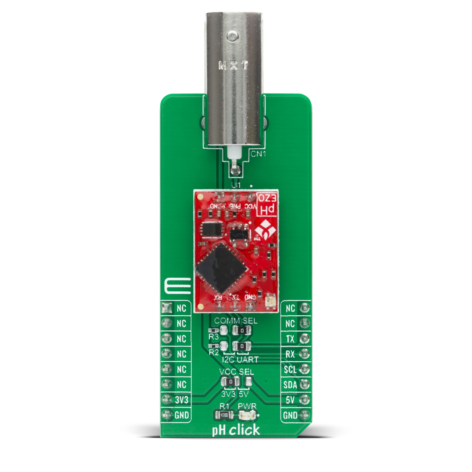
pH Click is a compact add-on board that provides an opportunity for the user to read pH with the same accuracy and capabilities as with some other expensive solutions. This board features the pH EZO™, a 6th generation embedded pH circuit that offers the highest level of stability and accuracy from AtlasScientific. With an easy to use data protocol, simple command structure, and flexible calibration protocol this Click board™ works with any off-the-shelf pH probe. It has temperature-dependent or independent readings with a full range of pH readings from 0.001 to 14.000. This Click board™ makes an excellent choice for applications where users want to add high accuracy pH readings to their future projects.
pH Click is supported by a mikroSDK compliant library, which includes functions that simplify software development. This Click board™ comes as a fully tested product, ready to be used on a system equipped with the mikroBUS™ socket.
Stock: Lead-time applicable.
| 5+ | R1,757.50 |
| 10+ | R1,665.00 |
| 15+ | R1,572.50 |
| 20+ | R1,513.30 |
NOTE: pH Probe does not come with this Click board™, if you are interested you can find Plastic pH Electrode BNC connector in our shop. Or you can buy the full package here.
How does it work?
pH Click is based on the pH EZO™, a 6th generation embedded pH circuit that offers the highest level of stability and accuracy from AtlasScientific. With an easy to use UART data protocol (with additional I2C serial interface), simple command structure and flexible calibration protocol that supports single-point, two-point, or three-point calibration, this Click board™ works well with any off-the-shelf pH probe. It has temperature-dependent or independent readings with a full range of pH readings from 0.001 to 14.000. Additional thorough and pictorial explanations of any of the calibration methods can be found in the attached datasheet.
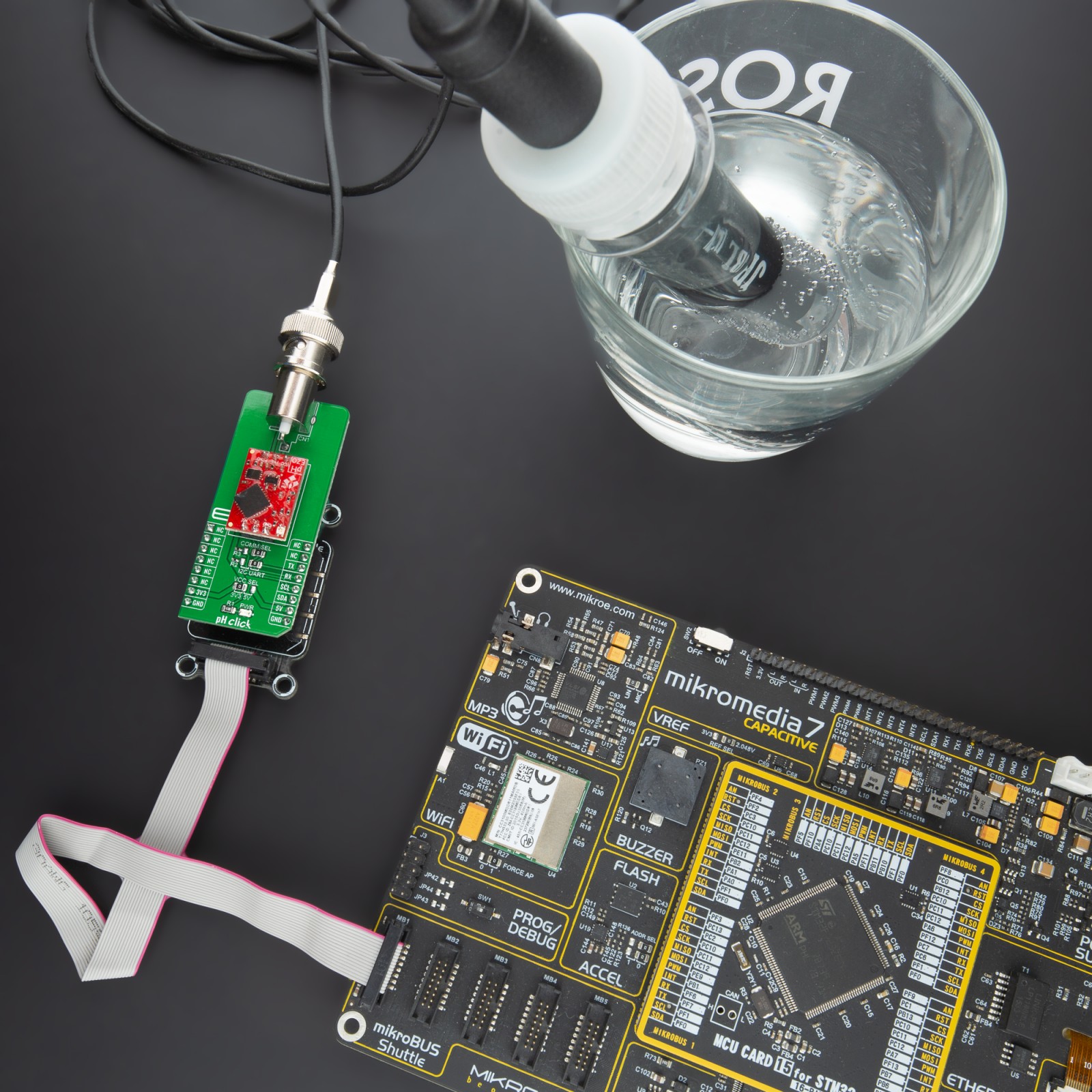
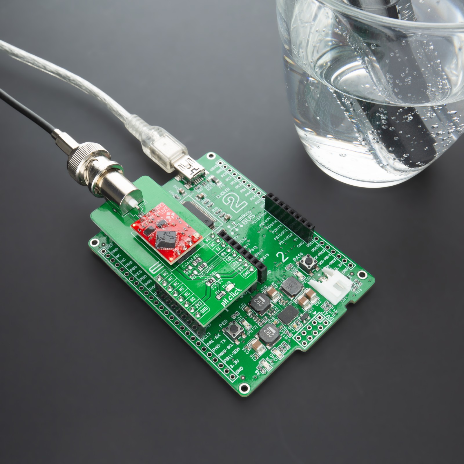
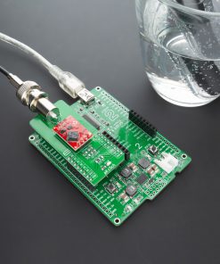
The pH EZO™ circuit is characterized by great sensitivity that gives its accuracy. When electrical noise is interfering with the pH readings, it is common to see rapidly fluctuating readings or readings that are consistently off. To verify that electrical noise is causing inaccurate readings, place the pH probe in a cup of water by itself. The pH readings should stabilize quickly, confirming that electrical noise was the issue.
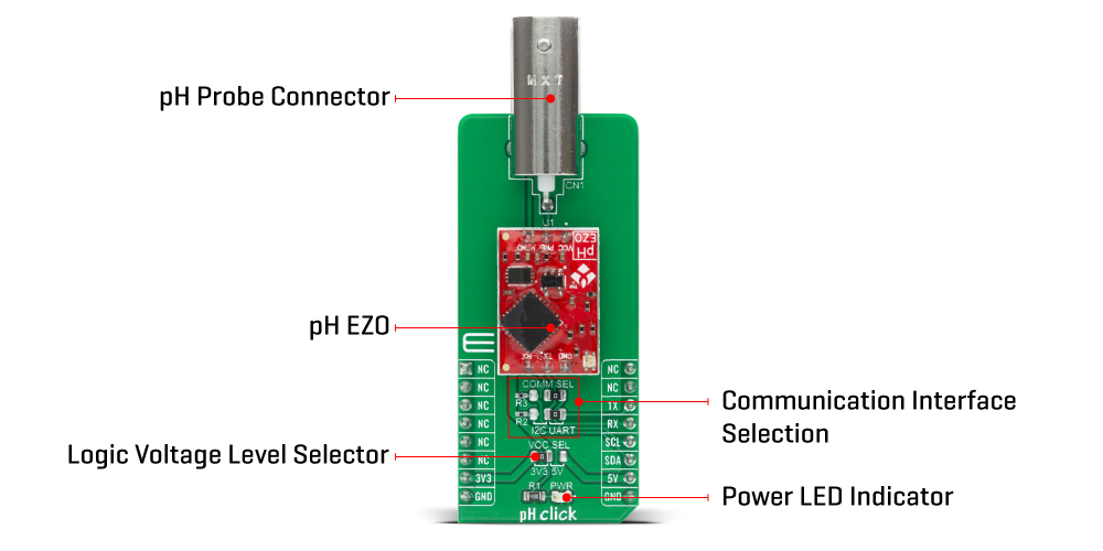
This Click Board™ uses the UART communication interface as its default communication protocol that supports all standard baud rates up to 115.200 but also provides the possibility of using the I2C serial interface. The selection can be performed by positioning SMD jumpers labeled as COMM SEL to an appropriate position. Note that all jumpers must be placed to the same side, or else the Click board™ may become unresponsive.
This Click Board™ uses the UART communication interface as its default communication protocol that supports all standard baud rates up to 115.200 but also provides the possibility of using the I2C serial interface. The selection can be performed by positioning SMD jumpers labeled as COMM SEL to an appropriate position. Note that all jumpers must be placed to the same side, or else the Click board™ may become unresponsive.
Also, the pH EZO™ circuit contains an LED indicator that informs the user about the current state of the pH circuit at any time with a specified color. The green color indicates Standby Mode, the yellow color indicates sent pH data, while the blue color indicates pH data being read. Besides, there is a purple color that signals a change in the Baud rate, a red color that represents an invalid command given by the user, and a white color that the LED flashes when a device is connected to the circuit.
This Click board™ is designed to operate with both 3.3V and 5V logic voltage levels selected via the VCC SEL jumper. It allows for both 3.3V and 5V capable MCUs to use the UART communication lines properly. However, the Click board™ comes equipped with a library that contains easy to use functions and an example code which can be used, as a reference, for further development.
Specifications
Type
Enviromental
Applications
Can be used for applications where users want to add high accuracy pH readings to their future projects.
On-board modules
pH Click is based on the pH EZO™, a 6th generation embedded pH circuit that offers the highest level of stability and accuracy from AtlasScientific.
Key Features
High stability and accuracy, easy to use data protocol, simple command structure, flexible calibration protocol, works with any off-the-shelf pH probe, and more.
Interface
I2C,UART
Compatibility
mikroBUS
Click board size
L (57.15 x 25.4 mm)
Input Voltage
3.3V or 5V
Pinout diagram
This table shows how the pinout on pH Click corresponds to the pinout on the mikroBUS™ socket (the latter shown in the two middle columns).
Onboard settings and indicators
| Label | Name | Default | Description |
|---|---|---|---|
| LD1 | PWR | – | Power LED Indicator |
| JP1 | VCC SEL | Left | Power Supply Voltage Selection 3V3/5V: Left position 3V3, Right position 5V |
| JP2-JP3 | COMM SEL | Right | Communication Interface Selection: Left position I2C, Right position UART |
pH Click electrical specifications
| Description | Min | Typ | Max | Unit |
|---|---|---|---|---|
| Supply Voltage | 3.3 | – | 5.5 | V |
| pH Measuring Range | 0.001 | – | 14.000 | NU |
| pH Resolution | – | 0.001 | – | NU |
| pH Accuracy | – | ±0.002 | – | NU |
| Operating Temperature Range | -40 | 25 | +85 | °C |
*NU – No Unit
Software Support
We provide a library for the pH Click on our LibStock page, as well as a demo application (example), developed using MikroElektronika compilers. The demo can run on all the main MikroElektronika development boards.
Library Description
The library covers all the functions necessary to control pH Click board™. It initializes and defines the UART drivers, and holds functions that allow full control of the device to the user.
Key functions:
void ph_send_cmd ( char *p_cmd );– Function is used to send command and does not expect response.void ph_perf_calib ( char *point, float flt_val, char *p_resp );– Function is used to perform calibration.ph_response ( char *p_resp );– Function is used to handle collected data.
Examples description
The application is composed of three sections :
- System Initialization – Initializes UART module and LOG structure.
- Application Initialization – Initalizes UART driver, sets up driver up the device, and performs a single point calibration.
- Application Task – This example shows capabilities of pH Click board™ by reading user’s perform single read input from USART terminal and performs reading of pH value of the supstance in which the probe is submerged and displaying readings via USART terminal.
void application_task ( )
{
    char cmd;

    ph_clr_log_buf( &log_txt[ 0 ] );
    if ( UART_Rdy_Ptr() )
    {
        cmd = UART_Rd_Ptr( );
        mikrobus_logWrite( "", _LOG_LINE );
        mikrobus_logWrite( " pH value: ", _LOG_TEXT );
        ph_send_cmd ( PH_CMD_SET_SNGL_READ );
        Delay_ms( 1000 );
        ph_response( &log_txt[ 0 ] );
        mikrobus_logWrite( &log_txt[ 0 ], _LOG_LINE );
    }
}
Additional Functions :
void float_to_str ( uint8_t byte_buf, uint8_t *str )– Wrapper FloatToStr for driver function.void long_word_to_str ( uint32_t long_word_buf, uint8_t *str )– Wrapper LongWordToStr for driver function.void byte_to_str ( uint8_t byte_buf, uint8_t *str )– Wrapper ByteToStr for driver function.
The full application code, and ready to use projects can be found on our LibStock page.
Other mikroE Libraries used in the example:
- UART
- Conversions
Additional notes and informations
Depending on the development board you are using, you may need USB UART click, USB UART 2 click or RS232 click to connect to your PC, for development systems with no UART to USB interface available on the board. The terminal available in all MikroElektronika compilers, or any other terminal application of your choice, can be used to read the message.
mikroSDK
This Click board™ is supported with mikroSDK – MikroElektronika Software Development Kit. To ensure proper operation of mikroSDK compliant Click board™ demo applications, mikroSDK should be downloaded from the LibStock and installed for the compiler you are using.
For more information about mikroSDK, visit the official page.
Resources
Downloads
| Weight | 26 g |
|---|---|
| Brand | MikroElektronika |

