How does it work?
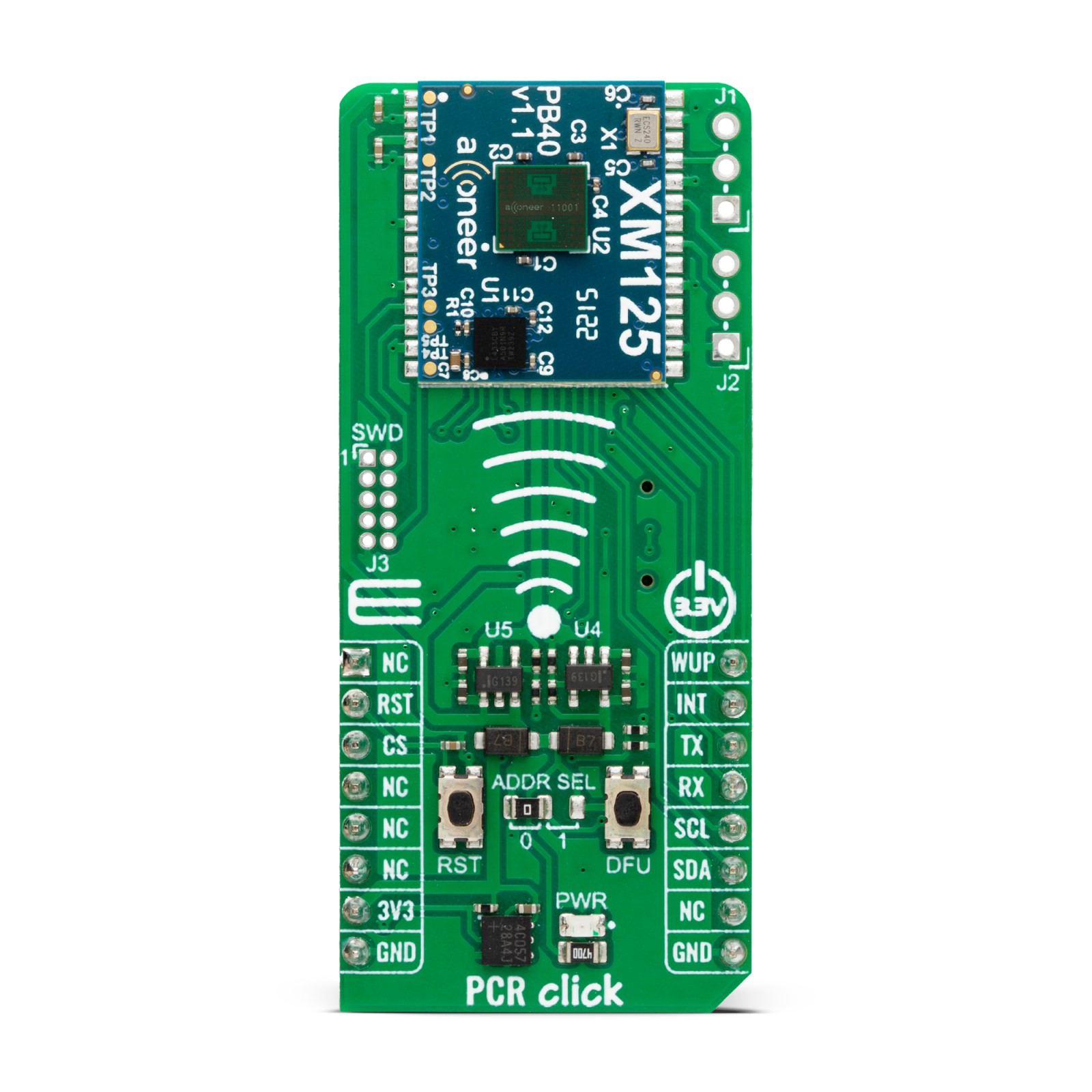
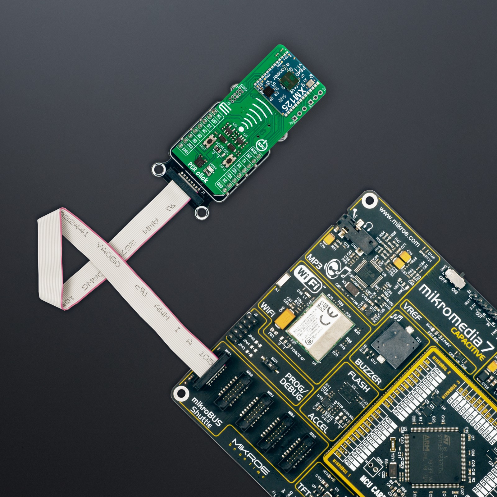
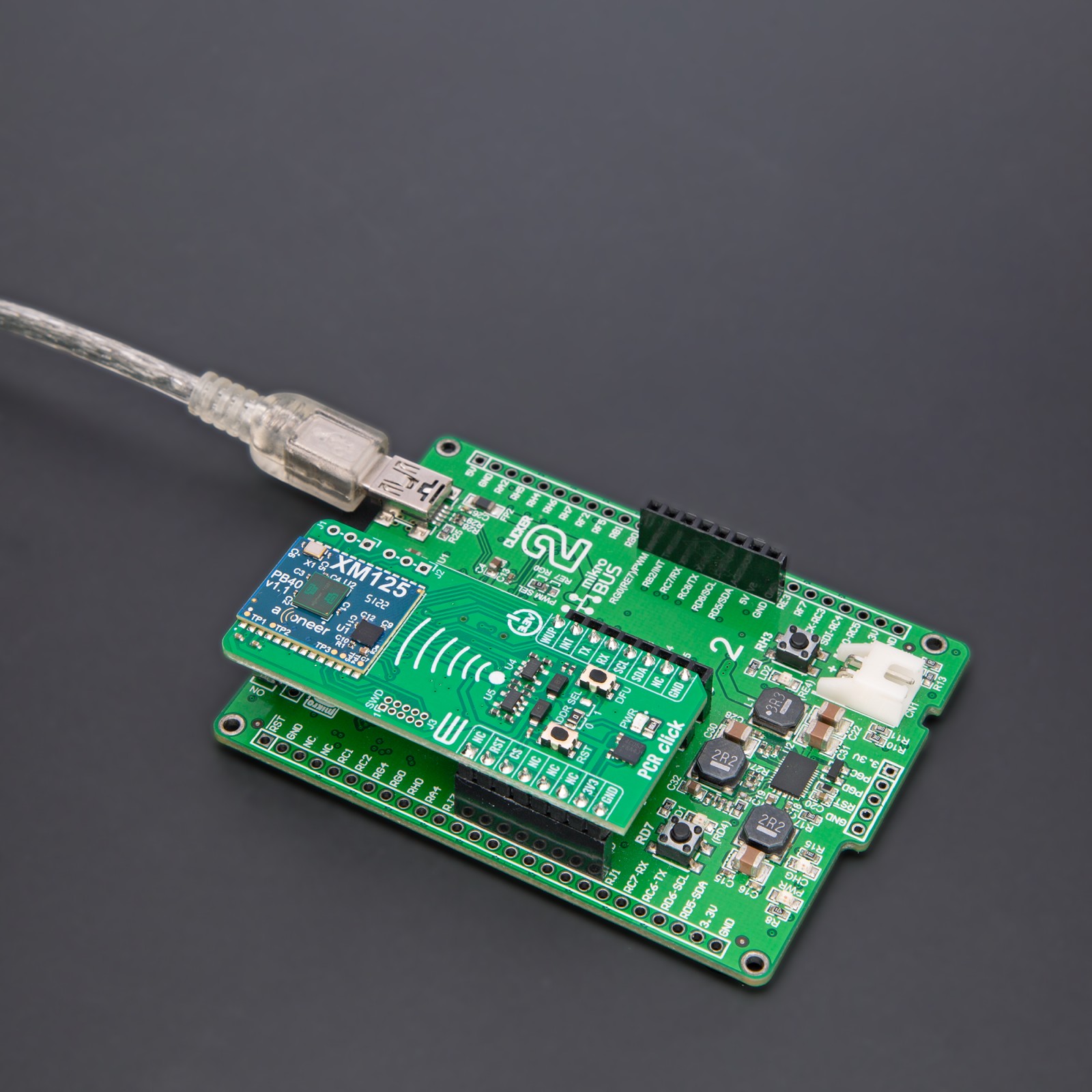
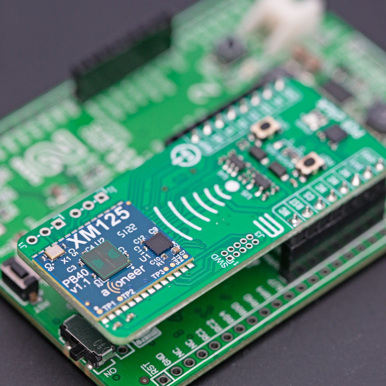
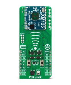
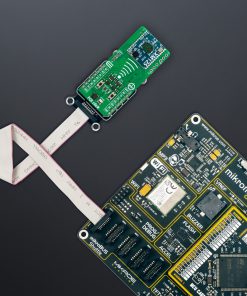
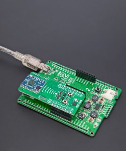
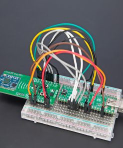
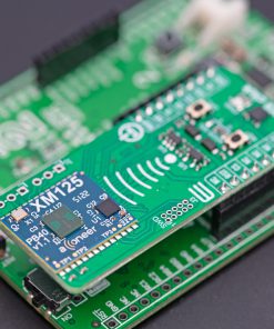
PCR Click is based on the XM125, the Entry+ PCR module from Acconeer. The A121 used in the module works on 60GHz and is optimized for ultra-low power consumption and high performance. It integrates baseband, RF front-end, and antenna. The A121 is unaffected by natural interference, such as dust, noise, color, and direct or indirect light. It can be used for distance and velocity measurements, object tracking, gesture control, monitoring, proximity, motion, and material detection. The radar can measure absolute and relative distance ranges in millimeters and up to 20m of distance.
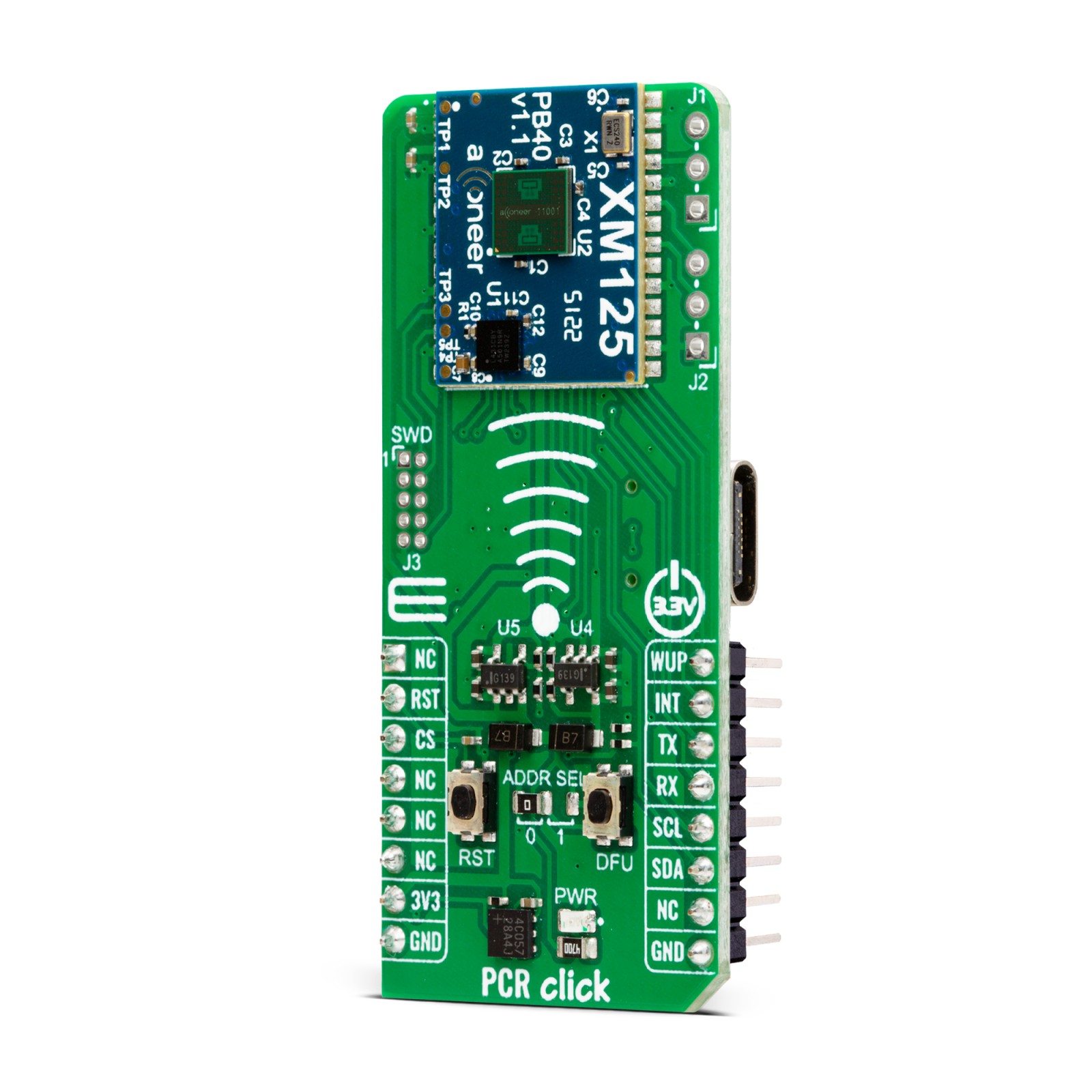
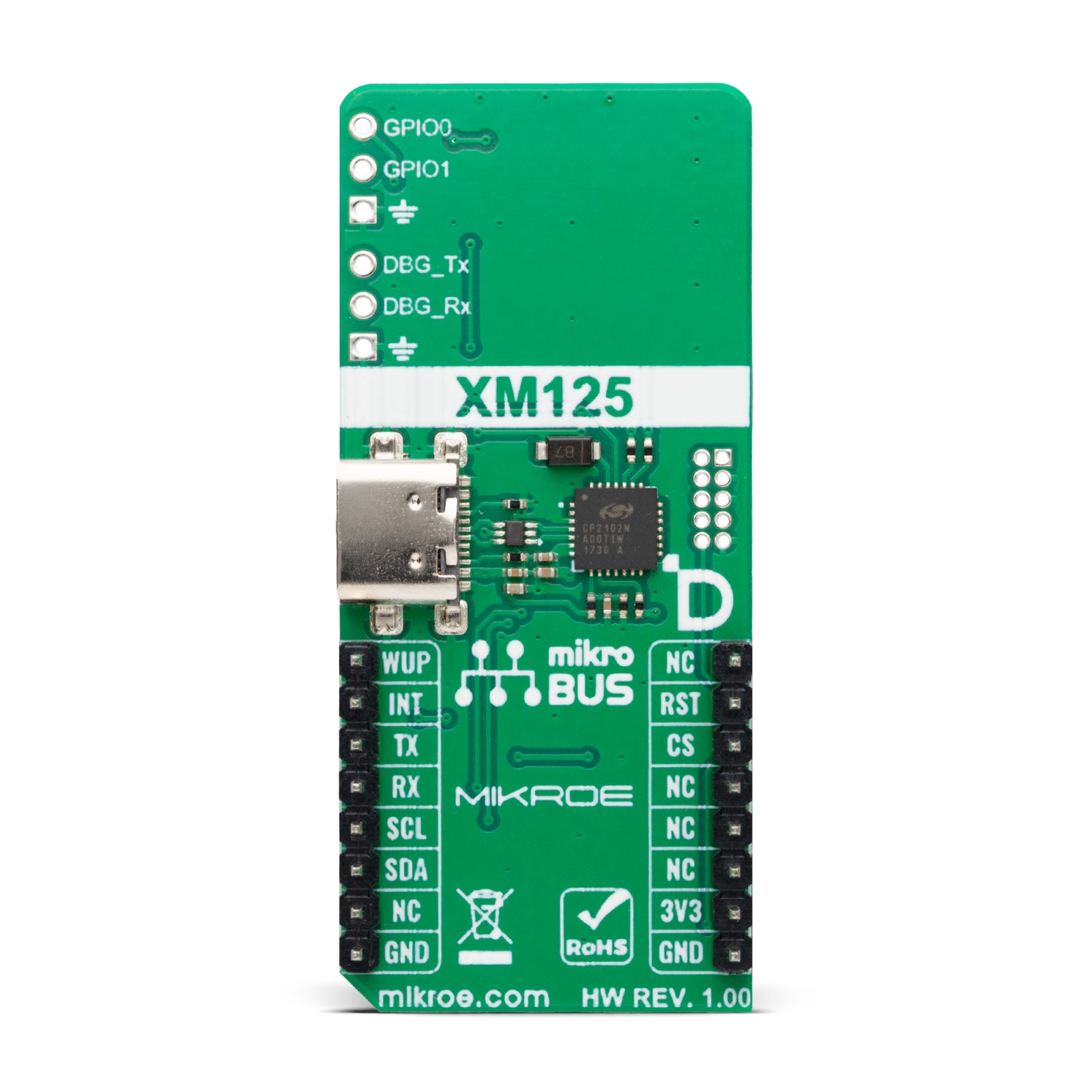
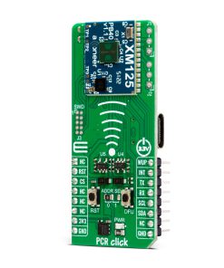
The module is delivered with a bootloader, allowing you to download the Acconeer Radar System Software (RSS) software and the SDK (Software Development Kit) for standalone usage, where customers can embed their application on top of RSS software. For this purpose, the XM125 is equipped with an STM32L 32-bit ARM Cortex-M4 MCU with an 80MHz clock speed. In addition, there are RST and DFU buttons that allow you to start the module in the embedded bootloader. The PCR Click uses a CP2102, a highly integrated USB-to-UART bridge from Silicon Labs, to allow you to connect it to the PC over the USB C connector. Besides evaluation and debugging, you can also flash the module’s USB C and UART interface.
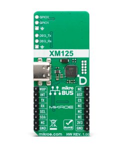
There are several headers on PCR Click. There is an SWD connector that you can use to upgrade the STM32L firmware. The J1 connector provides the GPIO0 and GPIO1 pins that are configurable for different functions. For debugging purposes, you can use a J2 connector and UART interface of the module with an external UART adapter.
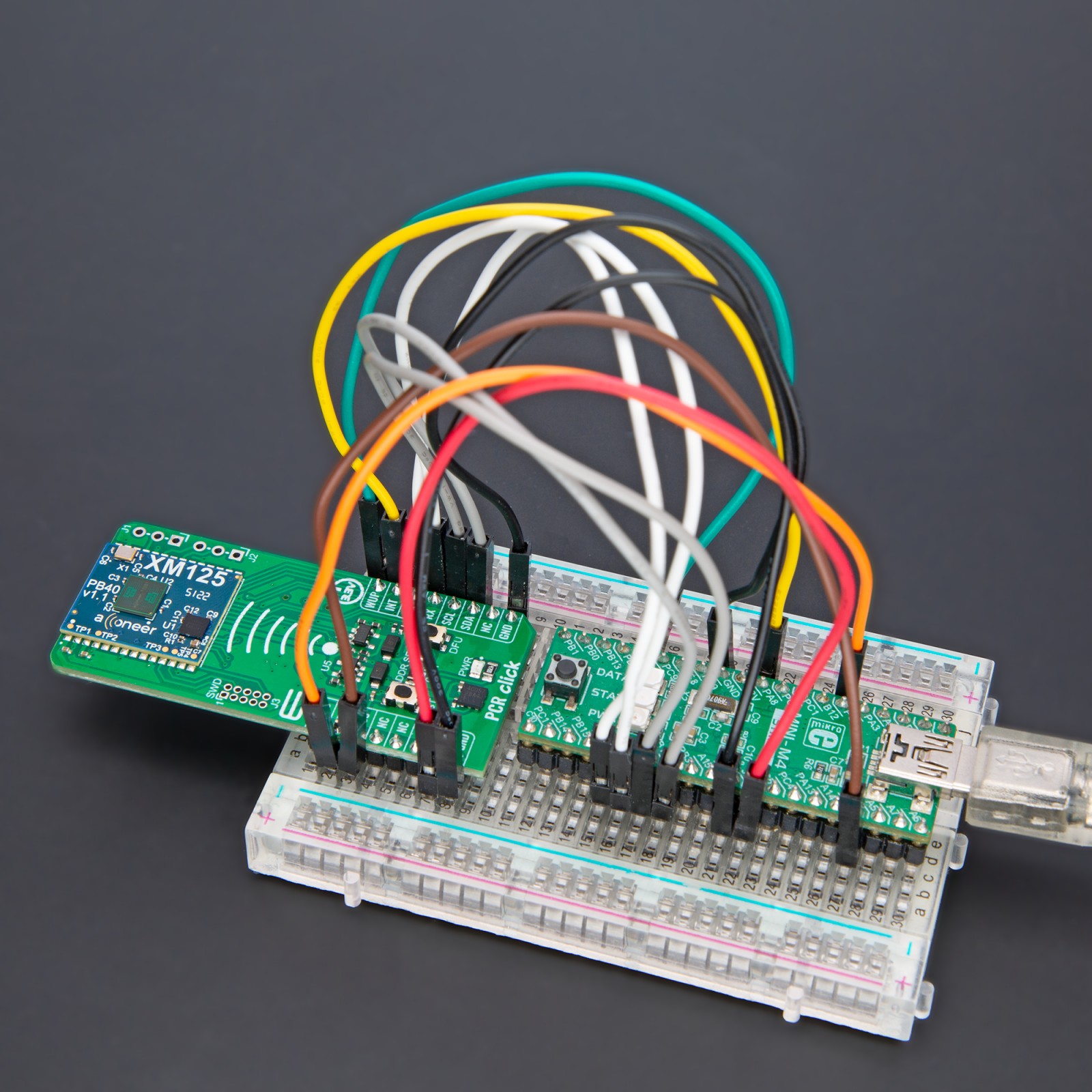
PCR Click uses a standard 2-wire UART interface to communicate with the host MCU with commonly used UART RX and TX pins. In addition, there is an I2C interface too. The I2C address can be selected over the ADDR SEL jumper. Besides the RST button, you can reset the module over the RST pin with a LOW logic State. In addition to resetting, you can wake up the module over the WUP pin. If an event occurs, the module can interrupt the host MCU over the INT pin.
This Click board™ can be operated only with a 3.3V logic voltage level. The board must perform appropriate logic voltage level conversion before using MCUs with different logic levels. Also, it comes equipped with a library containing functions and an example code that can be used as a reference for further development.
Specifications
Type
Proximity
Applications
Can be used for for developing high-precision people presence detection with the capability to recognize movement within configurable zones, motion detection, parking space occupancy detection, and level measurement in tanks or waste containers with configurable update frequency
On-board modules
XM125 – Entry+ PCR module from Acconeer
Key Features
Pulse coherent radar (PCR) with an integrated baseband, RF front-end and antenna in package (AiP), 32-bit ARM Cortex-M4 MCU, SWD/JTAG, integration of the device behind plastic or glass radomes without any need for a physical aperture, and more
Interface
I2C,UART,USB
Feature
ClickID
Compatibility
mikroBUS™
Click board size
L (57.15 x 25.4 mm)
Input Voltage
3.3V
Pinout diagram
This table shows how the pinout on PCR Click corresponds to the pinout on the mikroBUS™ socket (the latter shown in the two middle columns).
Onboard settings and indicators
Label | Name | Default | Description |
---|---|---|---|
LD1 | PWR | – | Power LED Indicator |
JP1 | ADDR SEL | Left | I2C Address Selection 0/1: Left position 0, Right position 1 |
T1 | RST | – | Reset Button |
T2 | DFU | – | DFU Button |
PCR Click electrical specifications
Description | Min | Typ | Max | Unit |
---|---|---|---|---|
Supply Voltage | – | 3.3 | – | V |
PCR Operating Frequency | – | – | 60 | GHz |
Proximity Distance Range | – | – | 20 | m |
Software Support
We provide a library for the PCR Click as well as a demo application (example), developed using MIKROE compilers. The demo can run on all the main MIKROE development boards.
Package can be downloaded/installed directly from NECTO Studio Package Manager(recommended), downloaded from our LibStock™ or found on Mikroe github account.
Library Description
This library contains API for PCR Click driver.
Key functions
-
pcr_write_reg
PCR register writing function. -
pcr_check_if_busy
PCR check if device is busy function. -
pcr_get_distance
PCR read distance function.
Example Description
This example demonstrates the use of PCR Click board™ by reading distance between click board and object.
void application_task ( void )
{
uint32_t distance_data = 0;
pcr_get_distance ( &pcr, &distance_data );
log_printf( &logger, " Distance: %lu mm rn", distance_data );
Delay_ms( 2000 );
}
The full application code, and ready to use projects can be installed directly from NECTO Studio Package Manager(recommended), downloaded from our LibStock™ or found on Mikroe github account.
Other Mikroe Libraries used in the example:
- MikroSDK.Board
- MikroSDK.Log
- Click.PCR
Additional notes and informations
Depending on the development board you are using, you may need USB UART click, USB UART 2 Click or RS232 Click to connect to your PC, for development systems with no UART to USB interface available on the board. UART terminal is available in all MIKROE compilers.
mikroSDK
This Click board™ is supported with mikroSDK – MIKROE Software Development Kit. To ensure proper operation of mikroSDK compliant Click board™ demo applications, mikroSDK should be downloaded from the LibStock and installed for the compiler you are using.
For more information about mikroSDK, visit the official page.