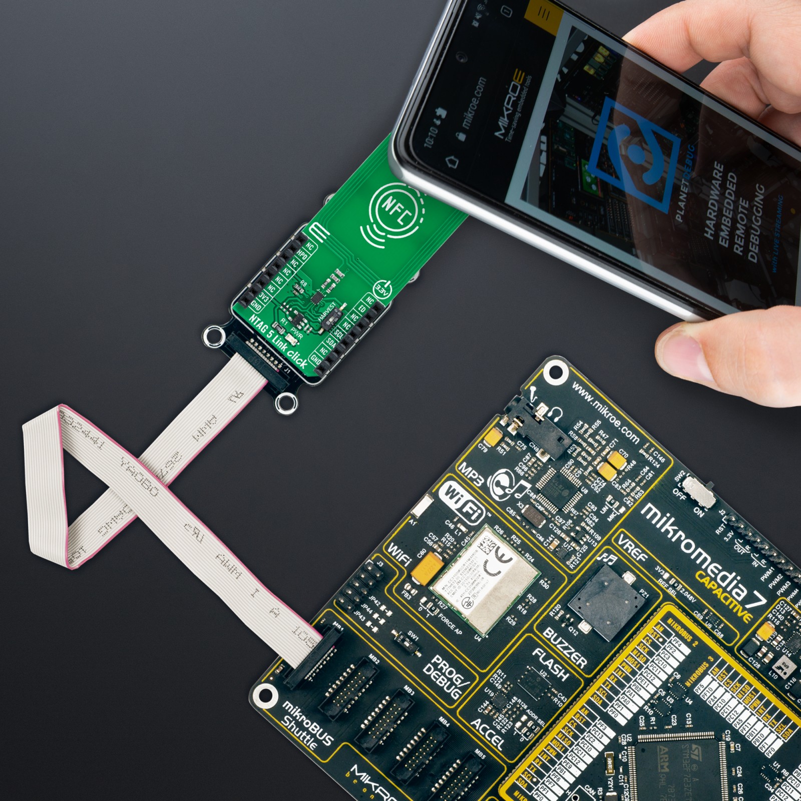
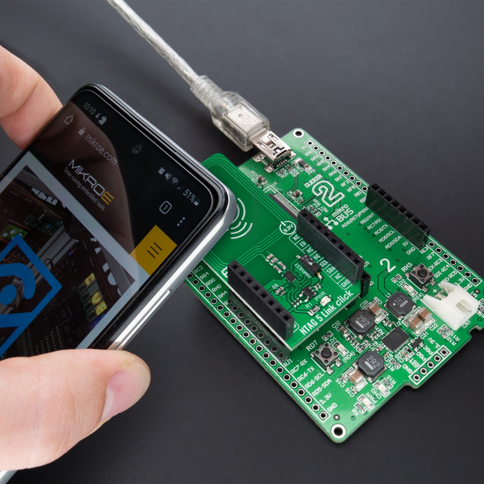
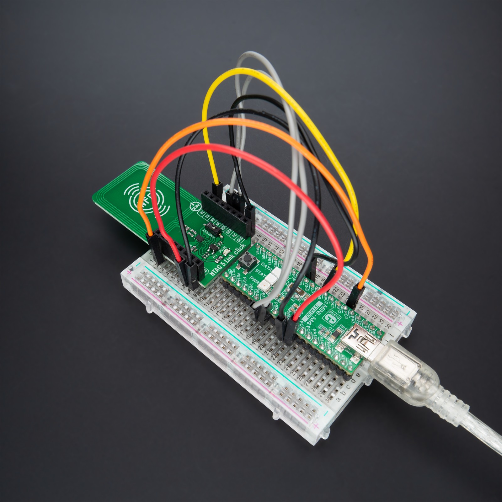
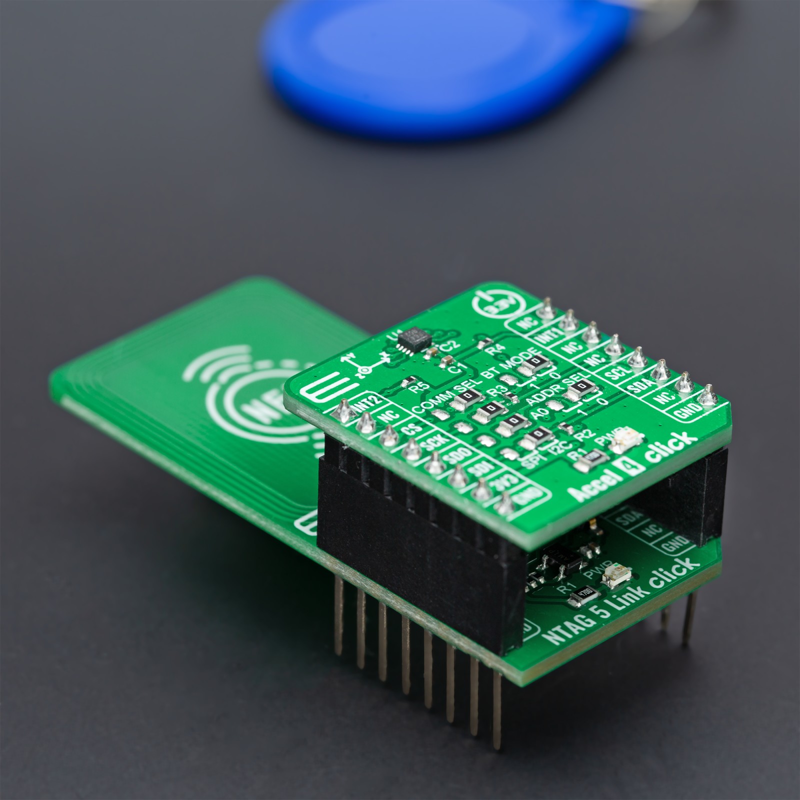
How does it work?
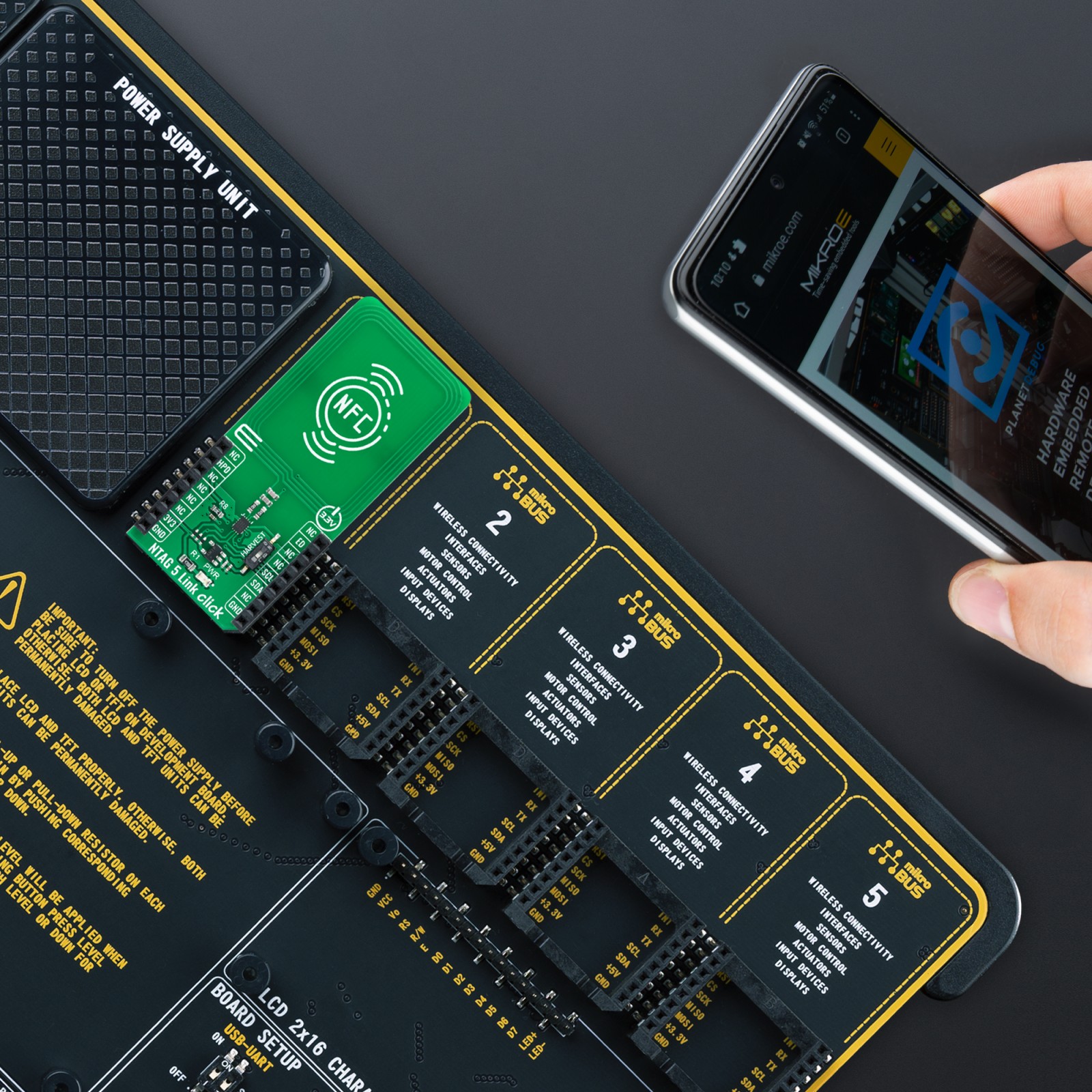
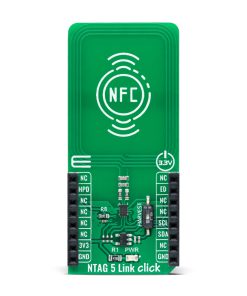
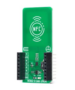
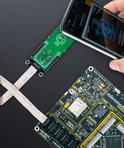
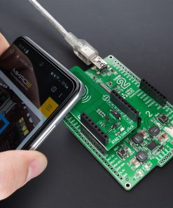
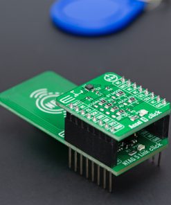
NTAG 5 Link Click as its foundation uses the NTP5332, a highly integrated NFC IC optimized for sensor-driven applications that act as a bridge between an NFC-enabled device and any I2C slave from NXP Semiconductors. This highly integrated NFC IC creates a secure, standard-based link from the device to the cloud, in a future-proof way to address and even power sensors. Operating at 13.56 MHz, the NTP5332 is an NFC Forum Type 5 Tag, which can be read and written by an NFC-enabled device at close range and an ISO/IEC 15693-enabled industrial reader over a more extended range (>60cm).
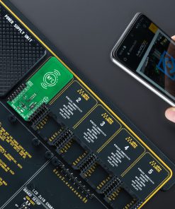
With NTAG 5 Link, the device can connect to the cloud with a single tap. The connection uses an NFC Forum-compliant data exchange mechanism involving SRAM to ensure interoperable data transfers. Also, it offers 2048 bytes of memory divided into three areas where each area can use a different protection level, varying from no protection to 32-/64-bit password-protected read/write access or up to 128-bit-AES mutual authentication protected read/write access. The NTAG 5 Link comes with pre-programmed proof-of-origin functionality to verify authenticity. The ECC-based originality signature can be reprogrammed or locked by the customer through its registers.
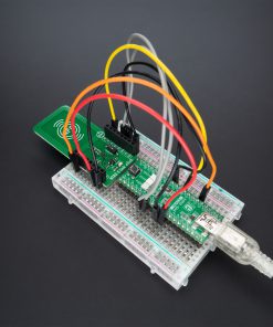
This Click board™ communicates with MCU using the standard I2C 2-Wire interface to read data and configure settings, supporting Standard Mode operation with a clock frequency of 100kHz and Fast Mode up to 400kHz. The NTP5332 also offers a transparent I2C master mode, for example, to read sensors without a microcontroller. The RF interface initiates an I2C Master communication, which can trigger a read or write transaction to an external I2C slave. Alongside this feature, an integrated SRAM is used as intermediate data storage. Session registers reflect the status of the I2C Master transaction. Therefore an RF reader has to poll for the status bits related to I2C Master to know the status of the current I2C transaction.
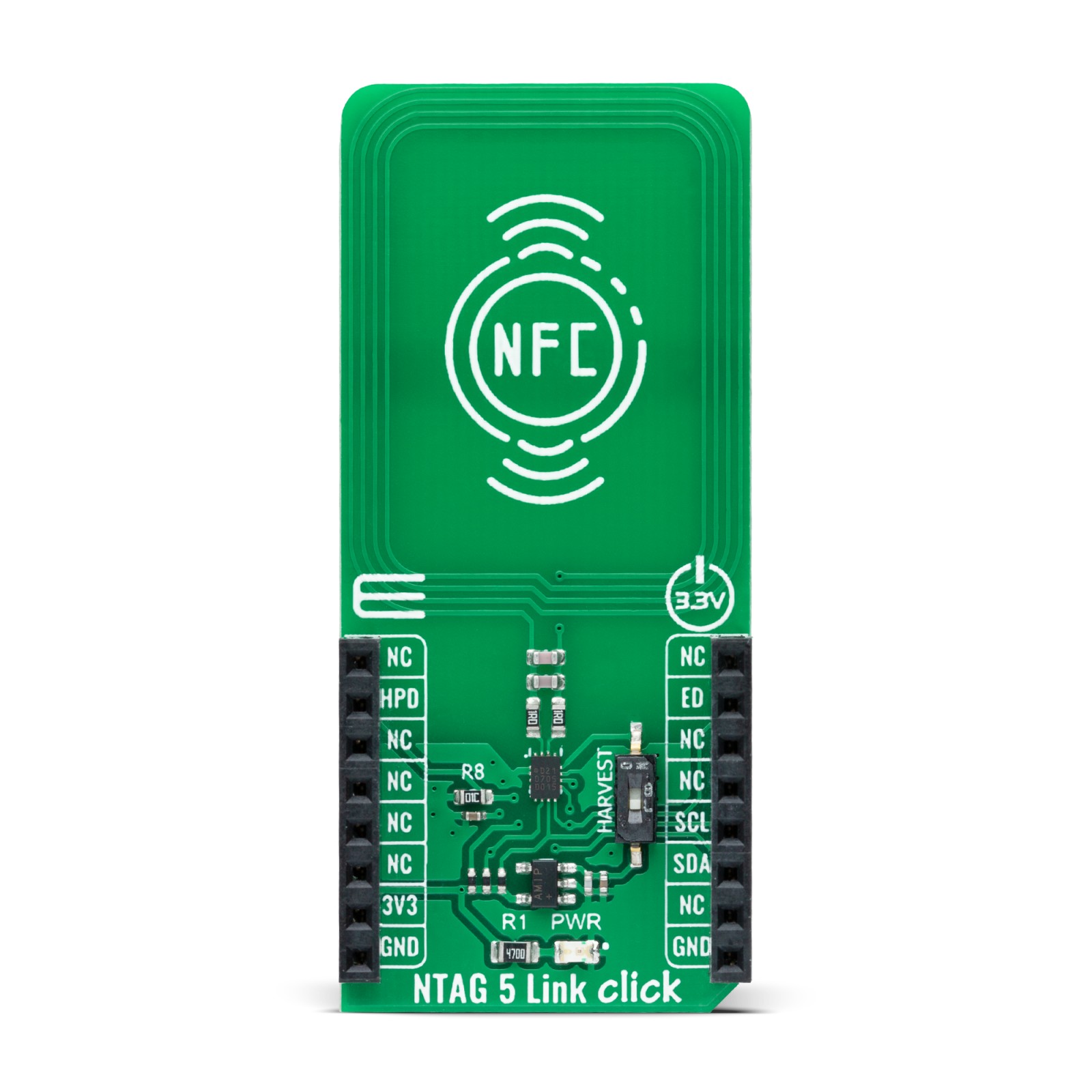
The NTAG 5 Link can also operate as a standalone solution by drawing power from the NFC field of an NFC device. It supports an energy harvesting feature, activated by an onboard switch marked as HARVEST, which means it can supply power to other components in the system, in this case, to supply the NTP5332. NTAG 5 Link can provide a fixed configurable voltage level of 1.8V, 2.4V, or 3V, selectable through register configuration when sufficient energy is available.
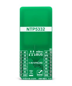
In addition, this Click board™ can be placed in a hard power-down mode by setting the HPD pin routed on the RST pin of the mikroBUS™ socket. Besides, it also has an event detection, and field detection functionality that defines the ED pin’s behavior routed on the INT pin of the mikroBUS™ socket. This pin’s behavior depends on various events such as the presence/absence of the NFC field, arbiter locked/unlocked EEPROM to NFC interface, Write/Read command ongoing, and more.
This Click board™ can be operated only with a 3.3V logic voltage level. The board must perform appropriate logic voltage level conversion before using MCUs with different logic levels. However, the Click board™ comes equipped with a library containing functions and an example code that can be used, as a reference, for further development.
Specifications
Type
RFID/NFC
Applications
Can be used for sensor-driven applications and represents an ideal solution for rapidly integrating NFC technology in any custom application
On-board modules
NTP5332 – highly integrated NFC IC which creates a secure standard-based link from the device to the cloud from NXP Semiconductors
Key Features
NFC Forum Type 5 Tag compliant, host interface configurable as an I2C master/slave, 32-byte reprogrammable originality signature, AES mutual authentication, event detection, energy harvest feature, and more
Interface
I2C
Feature
No ClickID
Compatibility
mikroBUS™
Click board size
L (57.15 x 25.4 mm)
Input Voltage
3.3V
Pinout diagram
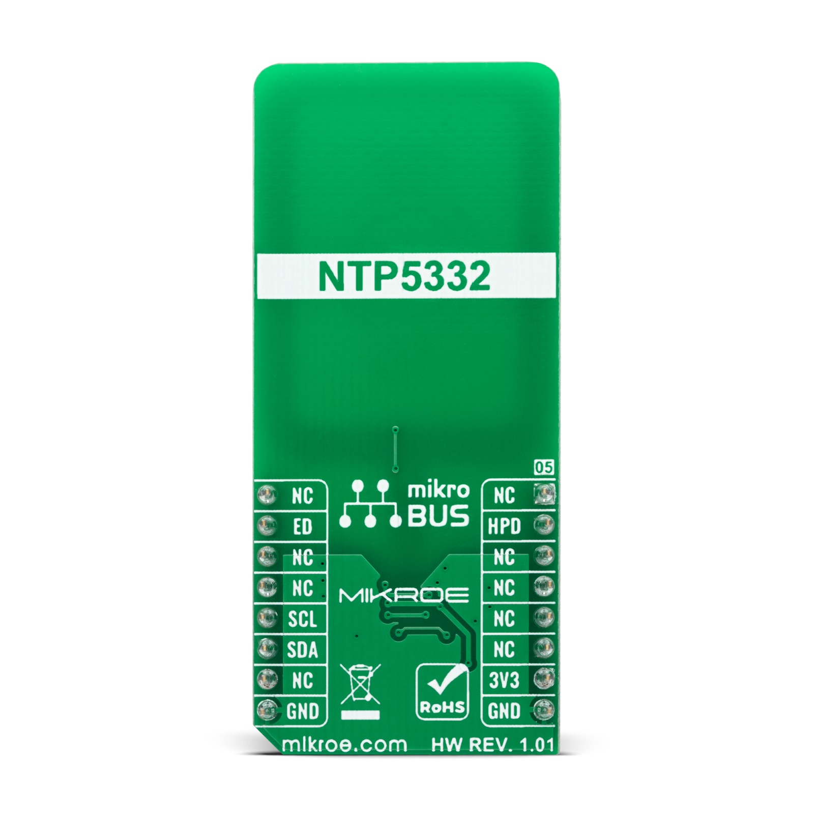
This table shows how the pinout on NTAG 5 Link Click corresponds to the pinout on the mikroBUS™ socket (the latter shown in the two middle columns).
Onboard settings and indicators
Label | Name | Default | Description |
---|---|---|---|
LD1 | PWR | – | Power LED Indicator |
SW1 | HARVEST | Lower | Energy Harvesting Activation Switch: Upper position ON, Lower position OFF |
NTAG 5 Link Click electrical specifications
Description | Min | Typ | Max | Unit |
---|---|---|---|---|
Supply Voltage | – | 3.3 | – | V |
Operating Frequency Range | 13.553 | 13.56 | 13.567 | MHz |
Operating Temperature Range | -40 | +25 | +85 | °C |
Software Support
We provide a library for the NTAG 5 Link Click as well as a demo application (example), developed using MikroElektronika compilers. The demo can run on all the main MikroElektronika development boards.
Package can be downloaded/installed directly from NECTO Studio Package Manager(recommended way), downloaded from our LibStock™ or found on Mikroe github account.
Library Description
This library contains API for NTAG 5 Link Click driver.
Key functions
-
ntag5link_write_ndef_uri_record
This function writes specific NDEF URI record to the memory address specified with NTAG5LINK_NDEF_MESSAGE_START_ADDRESS macro. -
ntag5link_write_message_to_memory
This function writes specified number of data bytes to the user memory starting from block_addr. -
ntag5link_read_message_from_memory
This function reads specified number of data bytes from the user memory starting from @b block_addr.
Example Description
This example demonstrates the use of NTAG 5 Link Click board™ by programming the specified NDEF URI record to the memory, and showing the memory read/write feature.
void application_task ( void )
{
uint8_t message_buf[ 100 ] = { 0 };
if ( NTAG5LINK_OK == ntag5link_write_message_to_memory ( &ntag5link,
TEXT_MESSAGE_ADDRESS,
TEXT_MESSAGE,
strlen ( TEXT_MESSAGE ) ) )
{
log_printf( &logger, " "%s" has been written to memory address 0x%.4X rn",
( char * ) TEXT_MESSAGE, TEXT_MESSAGE_ADDRESS );
}
if ( NTAG5LINK_OK == ntag5link_read_message_from_memory ( &ntag5link,
TEXT_MESSAGE_ADDRESS,
message_buf,
strlen ( TEXT_MESSAGE ) ) )
{
log_printf( &logger, " "%s" has been read from memory address 0x%.4X rnn",
message_buf, TEXT_MESSAGE_ADDRESS );
}
Delay_ms ( 5000 );
}
The full application code, and ready to use projects can be installed directly from NECTO Studio Package Manager(recommended way), downloaded from our LibStock™ or found on Mikroe github account.
Other Mikroe Libraries used in the example:
- MikroSDK.Board
- MikroSDK.Log
- Click.NTAG5Link
Additional notes and informations
Depending on the development board you are using, you may need USB UART click, USB UART 2 Click or RS232 Click to connect to your PC, for development systems with no UART to USB interface available on the board. UART terminal is available in all MikroElektronika compilers.
mikroSDK
This Click board™ is supported with mikroSDK – MikroElektronika Software Development Kit. To ensure proper operation of mikroSDK compliant Click board™ demo applications, mikroSDK should be downloaded from the LibStock and installed for the compiler you are using.
For more information about mikroSDK, visit the official page.