How does it work?
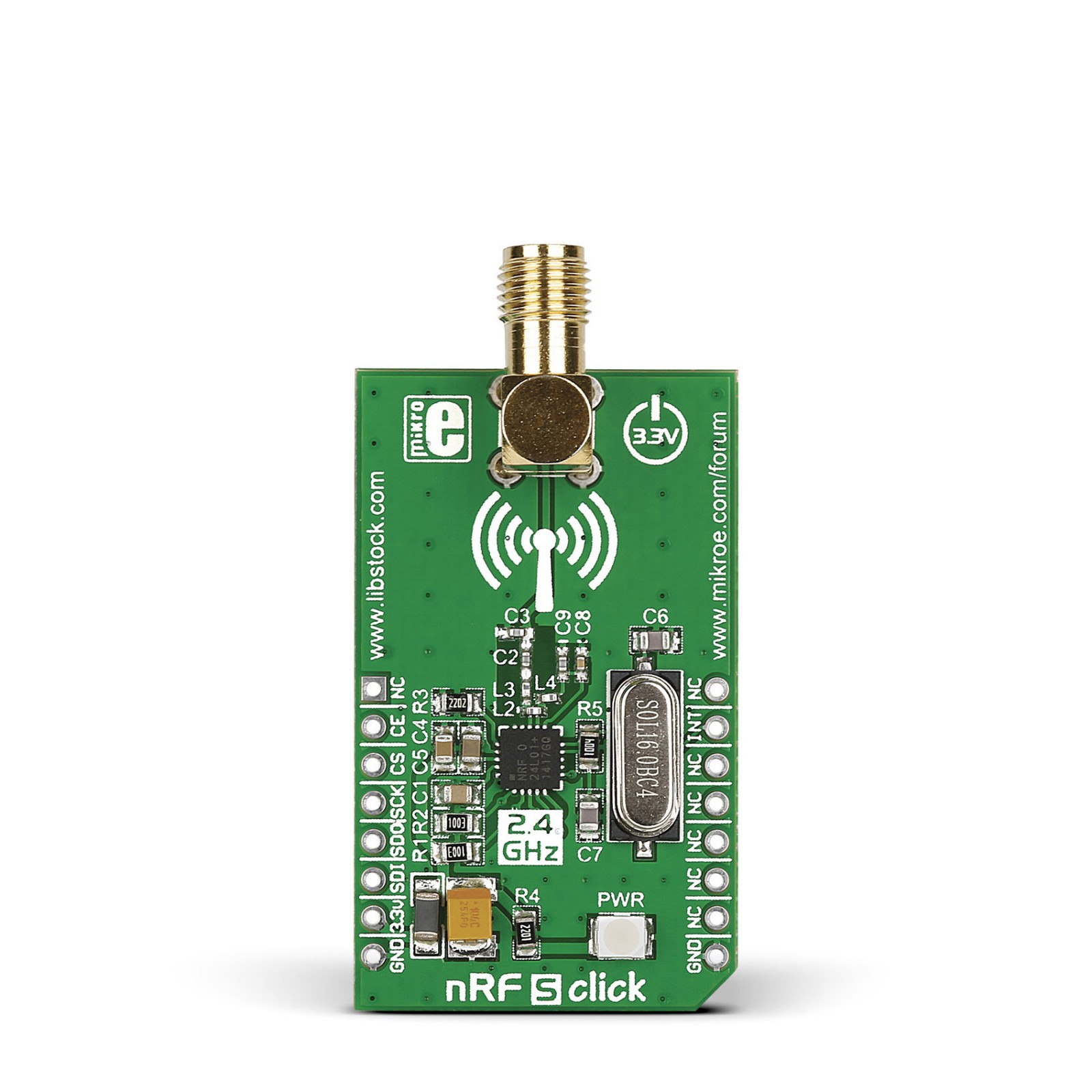
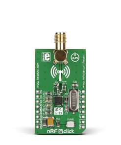
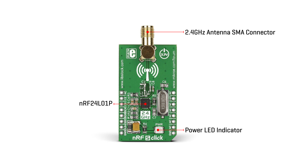
nRF S Click is based on the nRF24L01P, a low-power, high-performance 2.4GHz GFSK transceiver operating in the worldwide ISM frequency band from 2400MHz up to 2527MHz from Nordic Semiconductors. The nRF24L01P is either a transmitter or receiver with an embedded baseband protocol engine, Enhanced ShockBurst™, over an SMA connector and 2.4GHz SMA antenna is offered by Mikroe. The air data rate supported by nRF24L01P is configurable up to 2Mbps and is combined with two power-saving modes, making nRF S Click very suitable for ultra-low power designs. The embedded packet processing engines enable their entire operation with a simple MCU as a radio system. Auto packet handling, auto retransmission, and auto acknowledgment give reliable links without MCU interference.
The nRF24L01P has a user-defined built-in state machine and four operational modes: Power Down, Standby (I and II), and RX/TX. A transmitter and a receiver must be programmed with the same RF channel frequency to communicate with each other supporting a programmable air data rate of up to 2Mbps. The radio front end uses GFSK modulation and has user-configurable parameters like frequency channel, output power, and air data rate. Internal voltage regulators ensure a high Power Supply Rejection Ratio (PSRR) and a wide power supply range, although nRF S Click is 3.3V only.
The nRF S Click uses an SPI serial interface to communicate with the host MCU. An interrupt pin INT acts as a maskable active-low state interrupt used to set autonomous modes where the internal state machine controls the events (each autonomous mode/sequence is ended with an interrupt). The first Standby mode is defined by the low logic state on the chip enable pin, routed to the RST pin of the mikroBUS™ socket, while the other modes are defined by configurable PWR_UP and PRIM_RX registers.
This Click board™ can only be operated with a 3.3V logic voltage level. The board must perform appropriate logic voltage level conversion before using MCUs with different logic levels. However, the Click board™ comes equipped with a library containing functions and an example code that can be used as a reference for further development.
Specifications
Type
2.4 GHz Transceivers
Applications
Can be used for home appliances, remote control applications, consumer electronics, and more
On-board modules
nRF24L01P – GFSK transceiver operating in the worldwide ISM frequency band from Nordic Semiconductors
Key Features
Worldwide 2.4GHz ISM band operation, selectable data rate, low power consumption, SMA antenna connection, Enhanced ShockBurst™ baseband protocol engine, SPI interface, automatic packet handling, and more
Interface
GPIO,SPI
Feature
No ClickID
Compatibility
mikroBUS™
Click board size
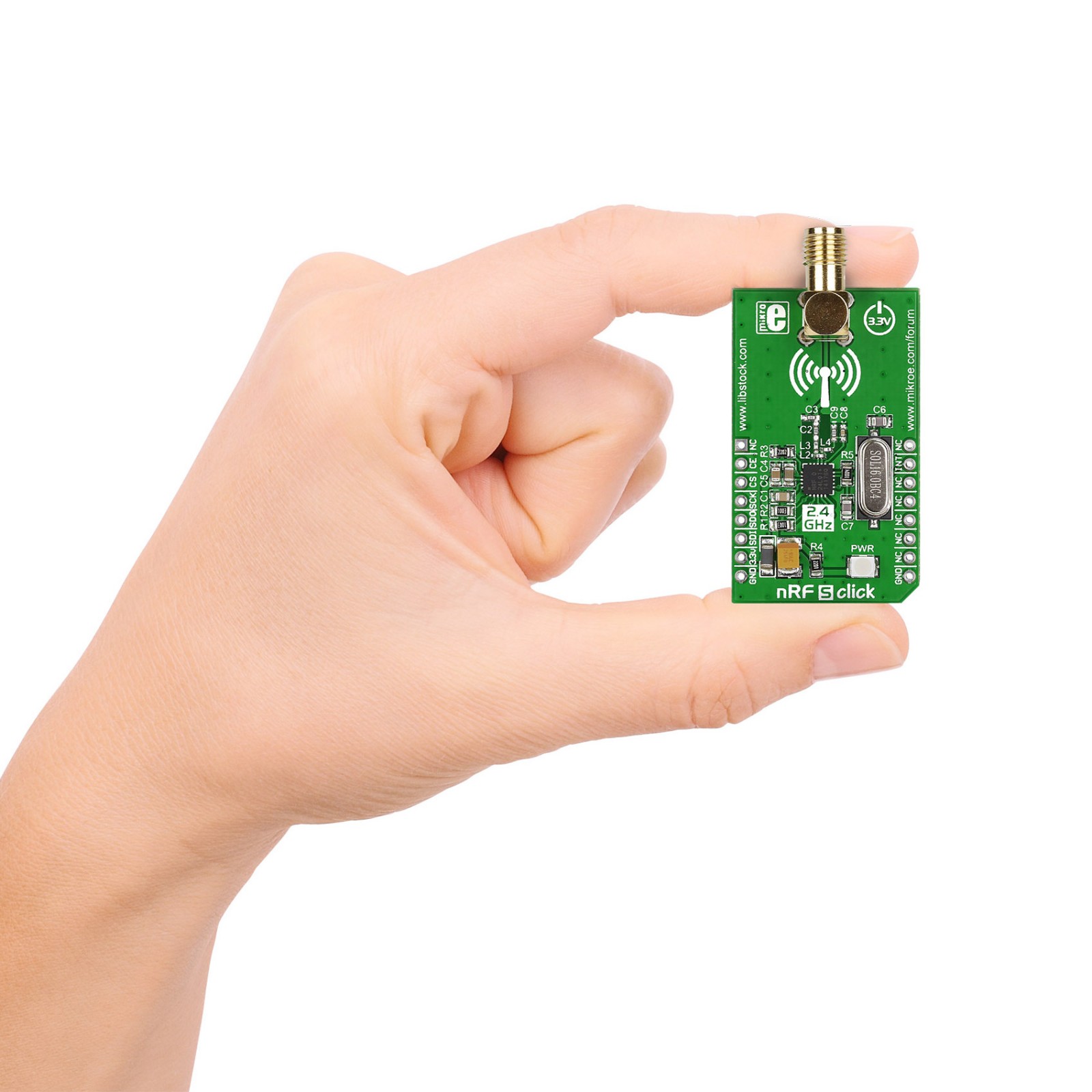
M (42.9 x 25.4 mm)
Input Voltage
3.3V
Pinout diagram
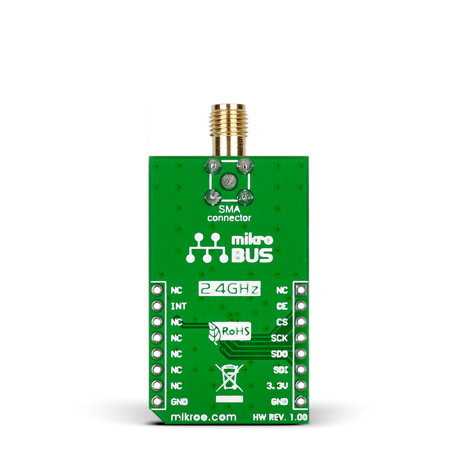
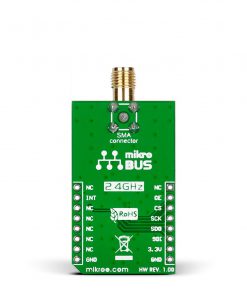
This table shows how the pinout on nRF S Click corresponds to the pinout on the mikroBUS™ socket (the latter shown in the two middle columns).
Onboard settings and indicators
Label | Name | Default | Description |
---|---|---|---|
LD1 | PWR | – | Power LED Indicator |
nRF S Click electrical specifications
Description | Min | Typ | Max | Unit |
---|---|---|---|---|
Supply Voltage | – | 3.3 | – | V |
Operating Frequency Range | 2400 | – | 2527 | MHz |
Air Data Rate | – | – | 2 | Mbps |