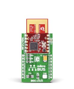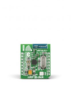
nRF C Click
R415.00 ex. VAT
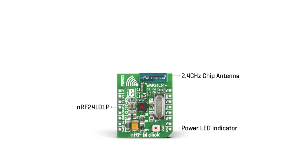
nRF C Click is a compact add-on board that contains a complete RF digital data transceiver. This board features the nRF24L01P, a low-power, high-performance 2.4GHz ISM GFSK transceiver from Nordic Semiconductors. The nRF24L01P transceiver is configurable through SPI serial interface and operates with only 3.3V in the worldwide ISM frequency band from 2400MHz up to 2525MHz. The embedded packet processing engines enable their entire operation with a simple MCU as a radio system. Burst mode transmission and up to 2Mbps air data rate make it suitable for ultra-low power consumption applications. This Click board™ is ideal for home appliances, remote control applications, consumer electronics, and many more.
nRF C Click is supported by a mikroSDK compliant library, which includes functions that simplify software development. This Click board™ comes as a fully tested product, ready to be used on a system equipped with the mikroBUS™ socket.
Stock: Lead-time applicable.
| 5+ | R394.25 |
| 10+ | R373.50 |
| 15+ | R352.75 |
| 20+ | R339.47 |
How does it work?
nRF C Click is based on the nRF24L01P, a low-power, high-performance 2.4GHz ISM GFSK transceiver operating in the worldwide ISM frequency band from 2400MHz up to 2527MHz, from Nordic Semiconductors. The nRF24L01P is either a transmitter or receiver with an embedded baseband protocol engine, Enhanced ShockBurst™, over an SMD 2.4GHz chip antenna. The air data rate supported by nRF24L01P is configurable up to 2Mbps and is combined with two power-saving modes, making nRF C Click very suitable for ultra-low power designs. The embedded packet processing engines enable their entire operation with a simple MCU as a radio system. Auto packet handling, auto retransmission, and auto acknowledgment give reliable links without any MCU interference.
The nRF24L01P has a user-defined built-in state machine and four operational modes: Power Down, Standby (I and II), and RX/TX. A transmitter and a receiver must be programmed with the same RF channel frequency to communicate with each other supporting a programmable air data rate of up to 2Mbps. The radio front end uses GFSK modulation and has user-configurable parameters like frequency channel, output power, and air data rate. Internal voltage regulators ensure a high Power Supply Rejection Ratio (PSRR) and a wide power supply range, although nRF C Click is 3.3V only.
The nRF C Click uses an SPI serial interface to communicate with the host MCU. An interrupt pin INT acts as a maskable active-low state interrupt used to set autonomous modes where the internal state machine controls the events (each autonomous mode/sequence is ended with an interrupt). The first Standby mode is defined by the low logic state on the chip enable pin, routed to the RST pin of the mikroBUS™ socket, while the other modes are defined by configurable PWR_UP and PRIM_RX registers.
This Click board™ can be operated only with a 3.3V logic voltage level. The board must perform appropriate logic voltage level conversion before using MCUs with different logic levels. However, the Click board™ comes equipped with a library containing functions and an example code that can be used, as a reference, for further development.
Specifications
Type
2.4 GHz Transceivers
Applications
Wireless PC peripherals, remotes, VoIP headsets, game controllers, sensors, home and commercial automation, active RFID, toys, etc
On-board modules
Nordic nRF24L01P 2.4 GHz transceiver
Key Features
Low power consumption, worldwide ISM band operation, support high air data rate, automatic packet processing, high performance, SPI interface, low power consumption, and more
Interface
SPI
Feature
No ClickID
Compatibility
mikroBUS™
Click board size
S (28.6 x 25.4 mm)
Input Voltage
3.3V
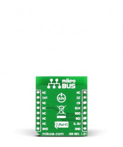
Pinout diagram
This table shows how the pinout on nRF C Click corresponds to the pinout on the mikroBUS™ socket (the latter shown in the two middle columns).
| Notes | Pin | Pin | Notes | ||||
|---|---|---|---|---|---|---|---|
| NC | 1 | AN | PWM | 16 | NC | ||
| Chip Enable | CE | 2 | RST | INT | 15 | INT | Interrupt |
| SPI Chip Select | CS | 3 | CS | RX | 14 | NC | |
| SPI Clock | SCK | 4 | SCK | TX | 13 | NC | |
| SPI Data OUT | SDO | 5 | MISO | SCL | 12 | NC | |
| SPI Data IN | SDI | 6 | MOSI | SDA | 11 | NC | |
| Power Supply | 3.3V | 7 | 3.3V | 5V | 10 | NC | |
| Ground | GND | 8 | GND | GND | 9 | GND | Ground |
Onboard settings and indicators
| Label | Name | Default | Description |
|---|---|---|---|
| LD1 | PWR | – | Power LED Indicator |
nRF C Click electrical specifications
| Description | Min | Typ | Max | Unit |
|---|---|---|---|---|
| Supply Voltage | – | 3.3 | – | V |
| Operating Frequency Range | 2400 | – | 2527 | MHz |
| Data Rate | – | – | 2 | Mbps |
Resources
Downloads
| Weight | 30 g |
|---|---|
| Brand | MikroElektronika |