How does it work?
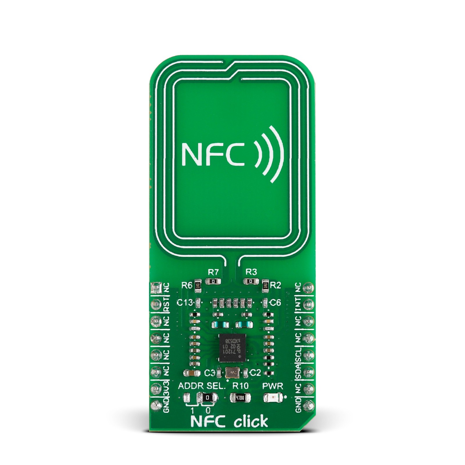
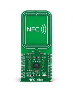
NFC Click is based on the PN7120, a full NFC forum-compliant controller with integrated firmware and NCI interface from NXP Semiconductors. The PN7120 implements the RF and all the low-level functionality, like an antenna driving and receiver circuitry, to realize an NFC Forum-compliant reader. It utilizes an outstanding modulation and demodulation concept for different contactless communication methods and protocols. The PN7120 fully complies with many Reader/Writer standards like ISO 14443A/B up to 848 kBit/s in under 25% of ASK modulation.
The NFC Click fully complies with the NFC Forum specifications, meaning it can behave as an NFC reader, a tag, or to establish a two-way connection with another NFC device. For this purpose, the NFC Click can work in several modes. In card emulation mode, it behaves like a smart card or a tag. It does not initiate communication; it only responds to an NFC reader. The Read/Write mode makes the NFC Click behave as an NFC reader, where it can communicate with a passive tag, smart card, or an NFC device that operates in a card emulation mode. Peer-to-Peer mode establishes a two-way communication channel between a pair of NFC-enabled devices.
The NFC Click uses a standard 2-Wire I2C interface to communicate with the host MCU and supports standard mode (100MHz), fast mode (400KHz), and high-speed mode (3.4MHz). The I2C address can be selected via the ADDR SEL jumper with 0 set by default. The PN7120 has two types of integrated memory: RAM and EEPROM. Internal registers of the PN7120 store configuration data, while the RF configuration for dedicated RF protocols is defined by EEPROM data, copied by a command issued from the host MCU. This allows users to achieve maximum RF performance from a given antenna design.
In addition to the I2C interface signals, this board uses several other signals from the mikroBUS™ socket. The reset pin routed on the RST pin of the mikroBUS™ socket provides the general reset ability, while the IRT pin of the mikroBUS™ socket represents an interrupt request to inform the host controller of various events.
This Click board™ can only be operated with a 3.3V logic voltage level. The board must perform appropriate logic voltage level conversion before using MCUs with different logic levels. However, the Click board™ comes equipped with a library containing functions and an example code that can be used, as a reference, for further development.
Specifications
Type
RFID/NFC
Applications
The tap-and-go nature of NFC makes many areas of life more convenient. From mobile payments to advertising, from home automation to building security
On-board modules
PN7120 IC
Key Features
FeliCa PCD mode, NFC Forum tag 1 to 4 (MIFARE Ultralight, Jewel, Open FeliCa tag, DESFire)
Interface
GPIO,I2C
Feature
No ClickID
Compatibility
mikroBUS™
Click board size
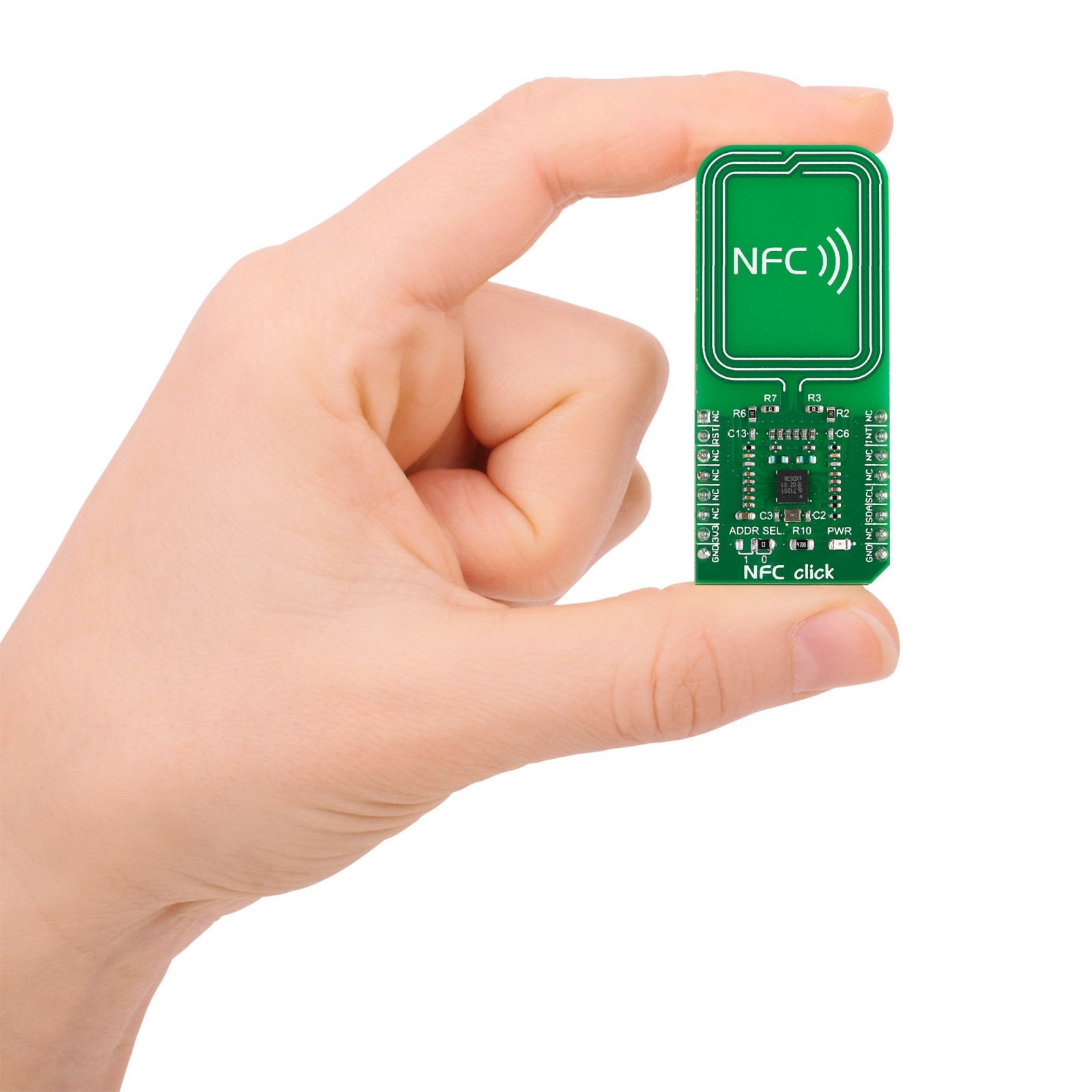
L (57.15 x 25.4 mm)
Input Voltage
3.3V
Pinout diagram
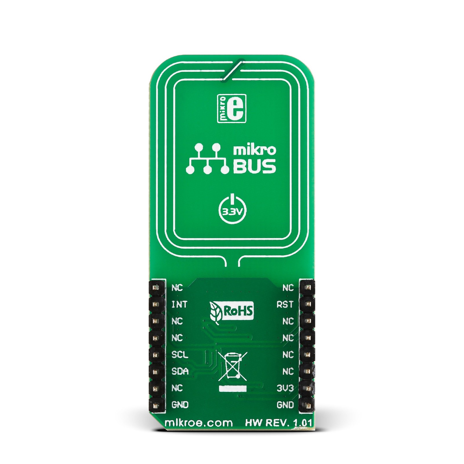
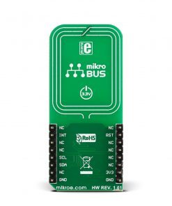
This table shows how the pinout on NFC Click corresponds to the pinout on the mikroBUS™ socket (the latter shown in the two middle columns).
Onboard settings and indicators
Label | Name | Default | Description |
---|---|---|---|
– | PWR | – | Power LED Indicator |
– | ADDR SEL | Right | I2C Address Selection 1/0: Left position 1, Right position 0 |
NFC Click electrical specifications
Description | Min | Typ | Max | Unit |
---|---|---|---|---|
Supply Voltage | – | 3.3 | – | V |
Operating Frequency | – | 13.56 | – | MHz |
Read/Write Speed | – | – | 848 | Kbit/s |
Software Support
We provide a library for the NFC Click as well as a demo application (example), developed using MIKROE compilers. The demo can run on all the main MIKROE development boards.
Package can be downloaded/installed directly from NECTO Studio Package Manager (recommended), downloaded from our LibStock™ or found on Mikroe github account.
Library Description
This library contains API for NFC Click driver.
Key functions
-
nfc_hw_reset
HW reset function. -
nfc_get_data
Get data function. -
nfc_cmd_disable_standby_mode
Disable standby mode command function.
Example Description
This is an example which demonstrates the usage of NFC Click board.
void application_task ( void )
{
while ( nfc_check_irq( &nfc ) == NFC_IRQ_STATE_HIGH )
{
nfc_read_nfc_data ( &nfc, &ctrl_pck_data );
}
while ( nfc_check_irq( &nfc ) == NFC_IRQ_STATE_LOW );
log_printf( &logger, "-----------------------rn" );
Delay_ms( 1000 );
}
The full application code, and ready to use projects can be installed directly from NECTO Studio Package Manager (recommended), downloaded from our LibStock™ or found on Mikroe github account.
Other Mikroe Libraries used in the example:
- MikroSDK.Board
- MikroSDK.Log
- Click.NFC
Additional notes and informations
Depending on the development board you are using, you may need USB UART click, USB UART 2 Click or RS232 Click to connect to your PC, for development systems with no UART to USB interface available on the board. UART terminal is available in all MIKROE compilers.
mikroSDK
This Click board™ is supported with mikroSDK – MIKROE Software Development Kit. To ensure proper operation of mikroSDK compliant Click board™ demo applications, mikroSDK should be downloaded from the LibStock and installed for the compiler you are using.
For more information about mikroSDK, visit the official page.