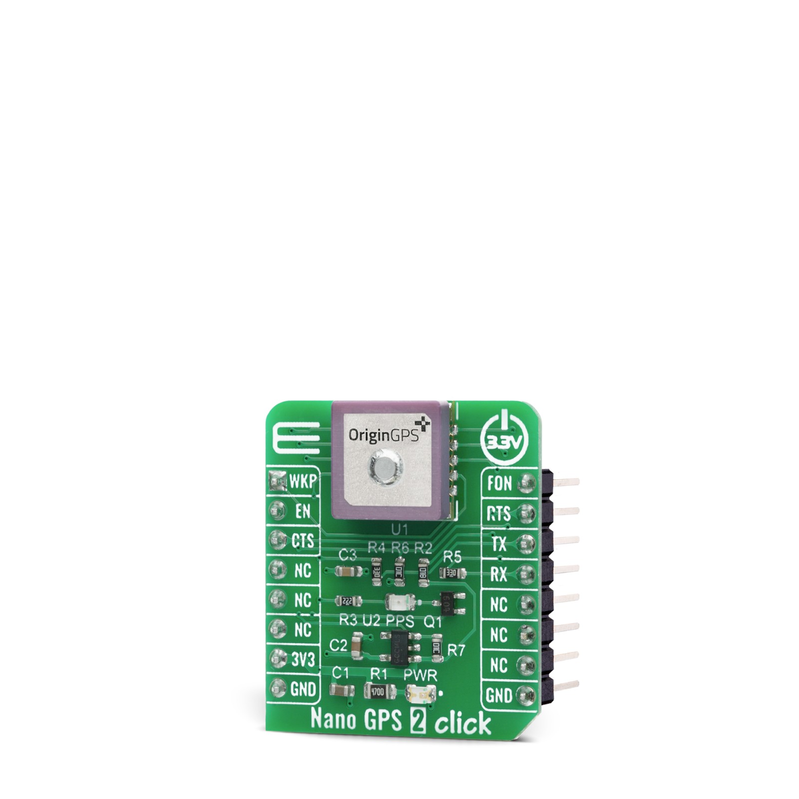
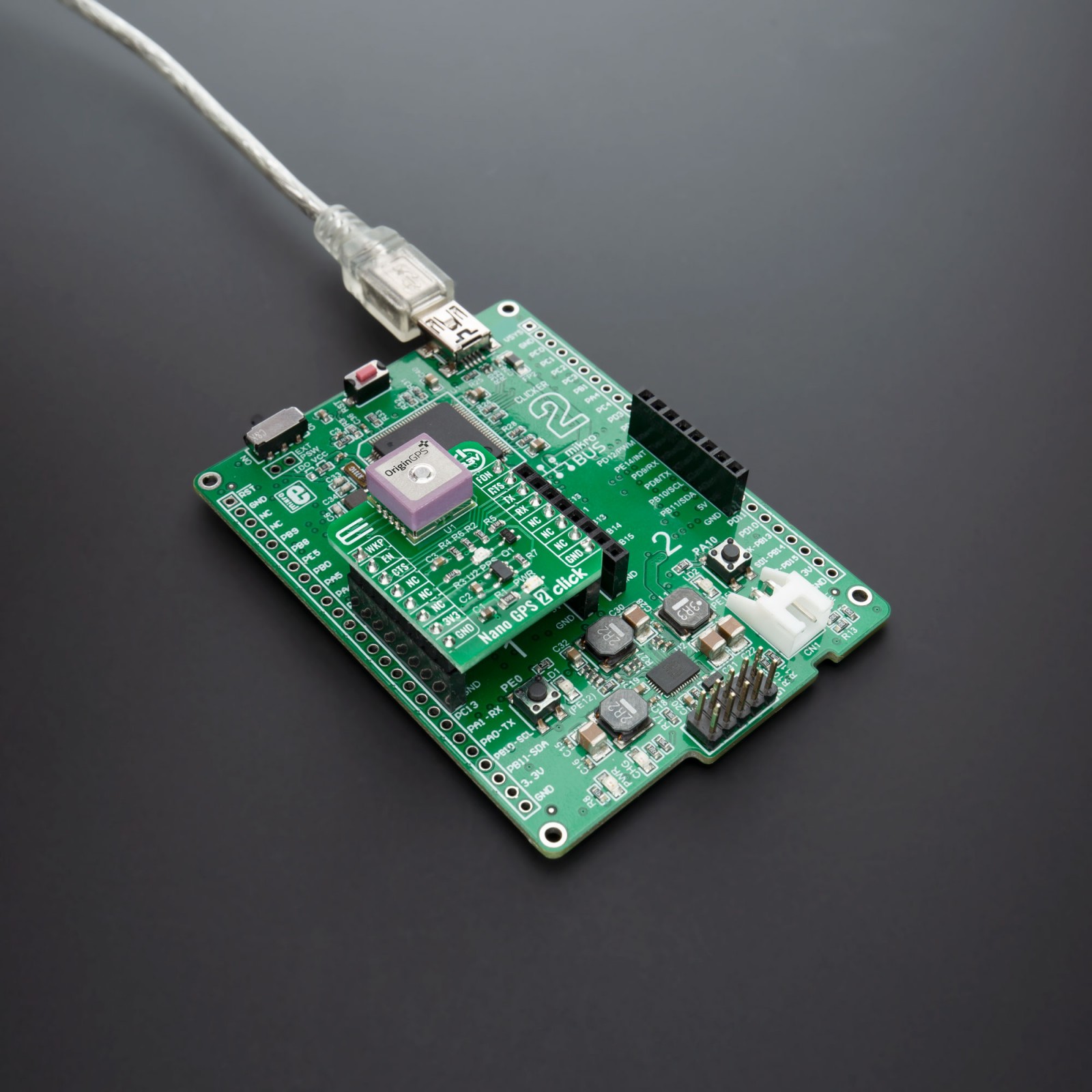
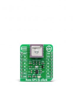
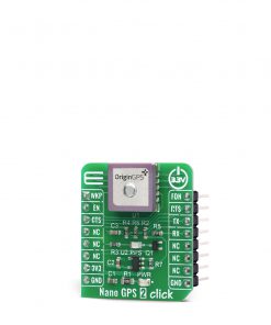
Nano GPS 2 Click
R930.00 ex. VAT
Nano GPS 2 Click features the smallest GPS module with an integrated patch antenna, the ORG1510-MK05 a module from OriginGPS. It’s the world’s smallest multi-constellation antenna module enabling high-performance in a variety of applications. Multi Micro Hornet ORG1510-MK05 module is introducing the industry’s lowest energy per fix ratio, unparalleled accuracy, and extremely fast fixes even under challenging signal conditions, such as in built-up urban areas, dense foliage or even indoor.
Despite its size, Nano GPS 2 Click offers superior sensitivity and outstanding performance, with time to first fix (TTFF) of less than 1 second, high accuracy of less than 2.5m, and tracking sensitivity down to -165dBm.
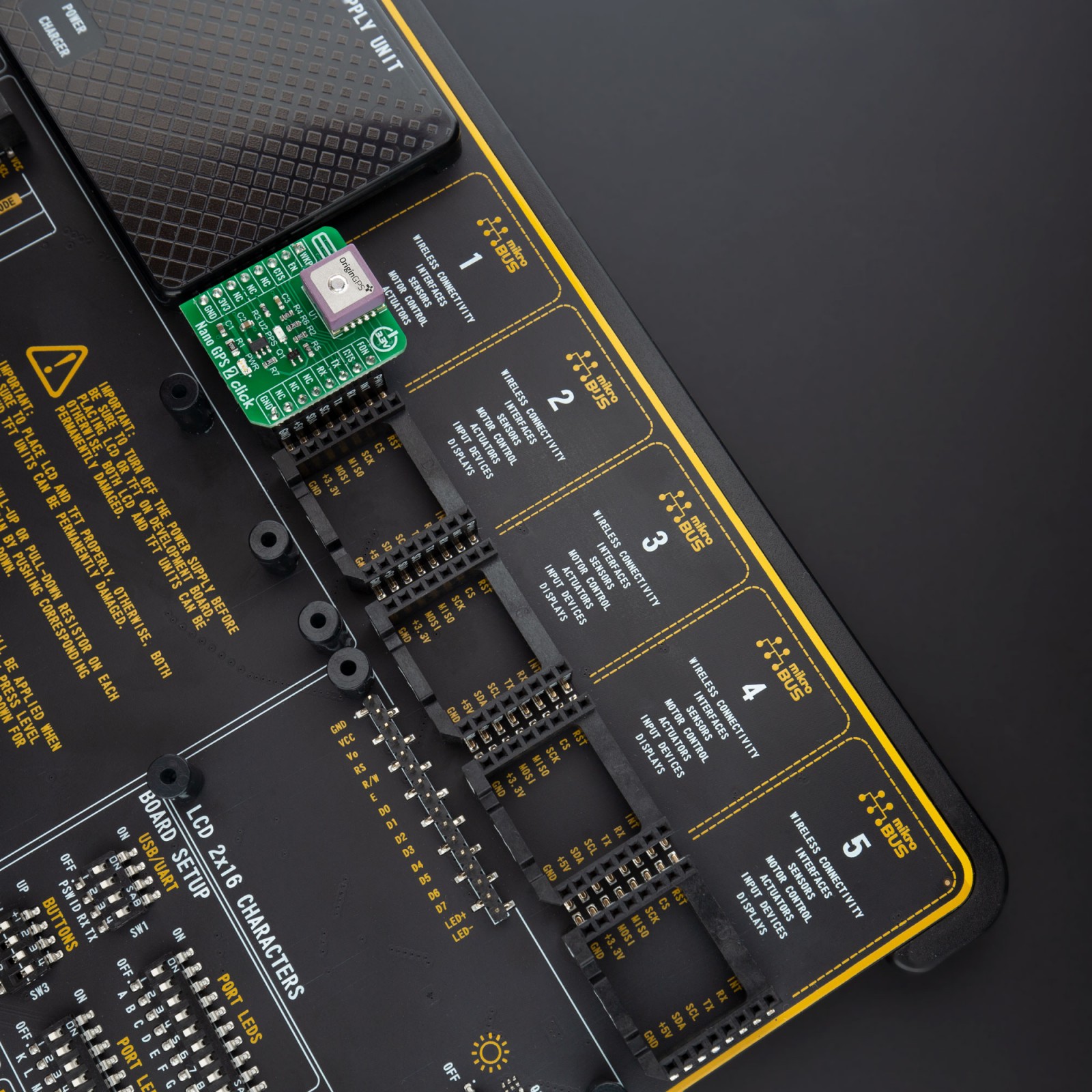
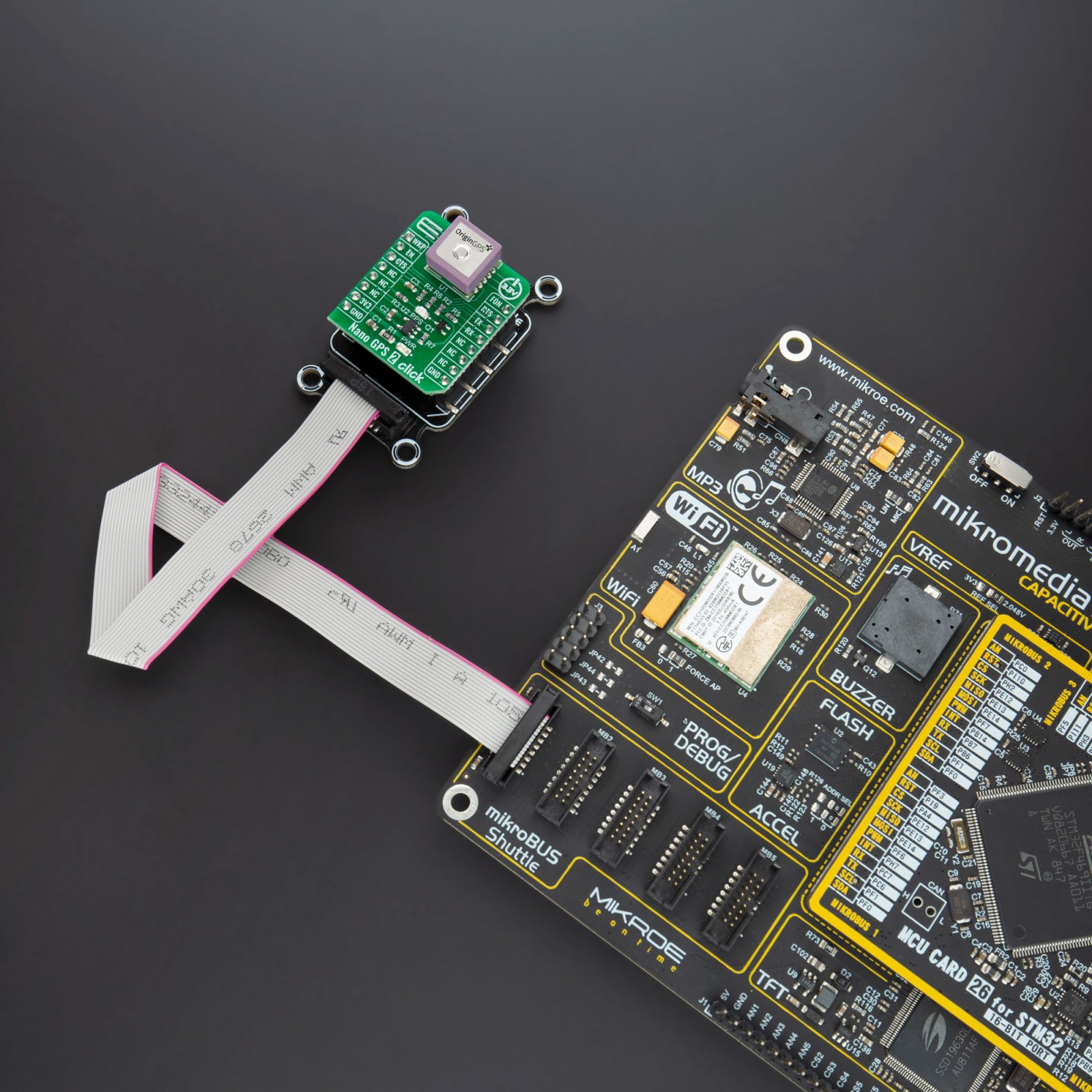
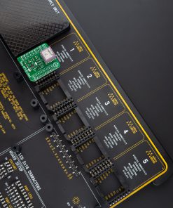
Nano GPS 2 Click is supported by a mikroSDK compliant library, which includes functions that simplify software development. This Click board™ comes as a fully tested product, ready to be used on a system equipped with the mikroBUS™ socket.
Stock: Lead-time applicable.
| 5+ | R883.50 |
| 10+ | R837.00 |
| 15+ | R790.50 |
| 20+ | R760.74 |
How does it work?
Nano GPS 2 Click uses the Multi Micro Hornet module from OriginGPS, the smallest GPS module with incorporated on‐board antenna element that is perfectly matched to receiver front‐end, frequency trimmed to GPS band, and Right‐Hand Circularly Polarized (RHCP). Module possesses dual-stage LNA (Low Noise Amplifier), SAW (Surface Acoustic Wave) filter, RTC crystal, GNSS SoC, and RF shield. GNSS SoC on a module is a hybrid positioning processor that combines many constellation configurations to provide a high-performance navigation solution such as GPS, GLONASS, GALILEO, BEIDOU, SBAS, QZSS, DGPS, and AGPS, allowing integration in embedded solutions with low computing resources.

The ORG1510-MK05 module supports operational modes that allow them to provide positioning information at reduced overall current consumption. The availability of GNSS signals in the operating environment will also be a factor in the choice of power management modes. The user can choose a mode that provides the best trade‐off of performance versus power consumption. Several power management modes can be enabled via a command such as:
- Full Power-Continuous Mode (for best GNSS performance)
- Power Save Mode (to optimize power consumption)
- Backup Mode (low quiescent power state where receiver operation is stopped)
Nano GPS 2 Click operates with received signal levels down to ‐167dBm and can be affected by high absolute levels of RF signals out of GNSS band, moderate levels of RF interference near the GNSS band, and by low‐levels of RF noise in GNSS band. Uses a standard UART port and besides the commonly used UART RX, TX, RTS, and CTS Nano GPS 2 Click have also FON, and WKP pins, which are routed to the PWM and AN pins of the mikroBUS™ socket, respectively.
Integrated GPS SoC incorporating a high-performance microprocessor and sophisticated firmware keeps positioning payload off the host, allowing integration in embedded solutions with low computing resources. Innovative architecture can detect changes in context, temperature, and satellite signals to achieve a state of near-continuous availability by maintaining and opportunistically updating its internal fine time, frequency, and satellite ephemeris data while consuming mere microwatts of battery power.
This Click Board™ is designed to be operated only with a 3.3V logic level. A proper logic voltage level conversion should be performed before the Click board™ is used with MCUs with logic levels of 5V. More information about the ORG1510-MK05 module can be found in the attached datasheet. However, this Click board™ comes equipped with a library that contains easy to use functions and a usage example that may be used as a reference for the development.
Specifications
Type
GPS/GNSS
Applications
Can be used for a rapid development and testing of various applications based on asset tracking, road navigation devices, public transport, wearable devices, etc.
On-board modules
Nano GPS 2 Click uses the Multi Micro Hornet ORG1510-MK05 module
Key Features
Superior sensitivity and outstanding performance, with time to first fix (TTFF) of less than 1 second, high accuracy of less than 2.5m, and tracking sensitivity down to -165dBm
Interface
GPIO,UART
Feature
No ClickID
Compatibility
mikroBUS™
Click board size
S (28.6 x 25.4 mm)
Input Voltage
3.3V
Pinout diagram
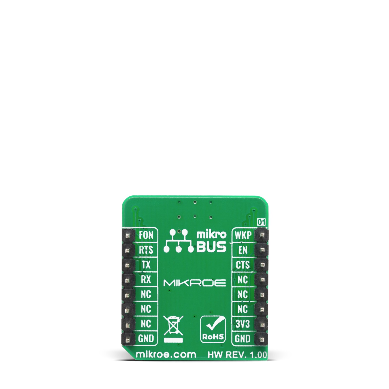
This table shows how the pinout on Nano GPS 2 Click corresponds to the pinout on the mikroBUS™ socket (the latter shown in the two middle columns).
Onboard settings and indicators
| Label | Name | Default | Description |
|---|---|---|---|
| LD1 | PWR | – | Power LED Indicator |
| LD2 | PPS | – | Pulse Per Second, when the GNSS receiver has established a connection with the satellite constellation the LED starts blinking |
Software Support
We provide a library for the Nano GPS 2 Click on our LibStock page, as well as a demo application (example), developed using MikroElektronika compilers. The demo can run on all the main MikroElektronika development boards.
Library Description
Library provides function for controlling GPIO, sending commands over UART module. There is generic parser that can parse response of specific command that device is sending, buffer for parser is getting data from process function that sends one byte of data to buffer, and there is function for clearing that buffer.
Key functions:
uint8_t nanogps2_generic_parser ( char *command, uint8_t element, char *parser_buf )– Generic parser functionvoid nanogps2_process ( char temp )– Process function that adds byte data to buffer for parsingvoid nanogps2_clear_rsp_buf ( void )– Function for clearing buffer for parsing
Examples description
The application is composed of three sections :
- System Initialization – Initialization of UART module and additional pins
- Application Initialization – UART interrupt initialization
- Application Task – Parsing RX data and logs GPS data if there is some every 2sec and then clears buffer.
void application_task ( )
{
    error_flag = NANOGPS2_DEV_OK;
    error_flag |= nanogps2_generic_parser( NANOGPS2_GNGGA_DATA_CMD,
                                           NANOGPS2_GNGGA_LONGITUDE,
                                           &p_lon[ 0 ] );
    error_flag |= nanogps2_generic_parser( NANOGPS2_GNGGA_DATA_CMD,
                                           NANOGPS2_GNGGA_LATITUDE,
                                           &p_lat[ 0 ] );
    error_flag |= nanogps2_generic_parser( NANOGPS2_GNGGA_DATA_CMD,
                                           NANOGPS2_GNGGA_ALTITUDE,
                                           &p_alt[ 0 ] );

    if ( ( NANOGPS2_DEV_OK == error_flag ) &&
         ( p_lon[0] != 0 ) && ( p_lat[0] != 0 ) && ( p_alt[0] != 0 ) )
    {
        mikrobus_logWrite( " - Latitude: ", _LOG_TEXT );
        mikrobus_logWrite( p_lat, _LOG_LINE );
        mikrobus_logWrite( " - Longitude: ", _LOG_TEXT );
        mikrobus_logWrite( p_lon, _LOG_LINE );
        mikrobus_logWrite( " - Altitude: ", _LOG_TEXT );
        mikrobus_logWrite( p_alt, _LOG_LINE );
        mikrobus_logWrite( "-------------------------------------", _LOG_LINE );
        memset( &p_lat[ 0 ], 0, 50 );
        memset( &p_lon[ 0 ], 0, 50 );
        memset( &p_alt[ 0 ], 0, 50 );
    }

    if ( NANOGPS2_DEV_OK == error_flag )
    {
        nanogps2_clear_rsp_buf(  );
    }
}
The full application code, and ready to use projects can be found on our LibStock page.
Other mikroE Libraries used in the example:
- CString
- UART
Additional notes and informations
Depending on the development board you are using, you may need USB UART click, USB UART 2 click or RS232 click to connect to your PC, for development systems with no UART to USB interface available on the board. The terminal available in all MikroElektronika compilers, or any other terminal application of your choice, can be used to read the message.
mikroSDK
This Click board™ is supported with mikroSDK – MikroElektronika Software Development Kit. To ensure proper operation of mikroSDK compliant Click board™ demo applications, mikroSDK should be downloaded from the LibStock and installed for the compiler you are using.
For more information about mikroSDK, visit the official page.
Resources
Downloads
| Weight | 19 g |
|---|---|
| Brand | MikroElektronika |


