How does it work?
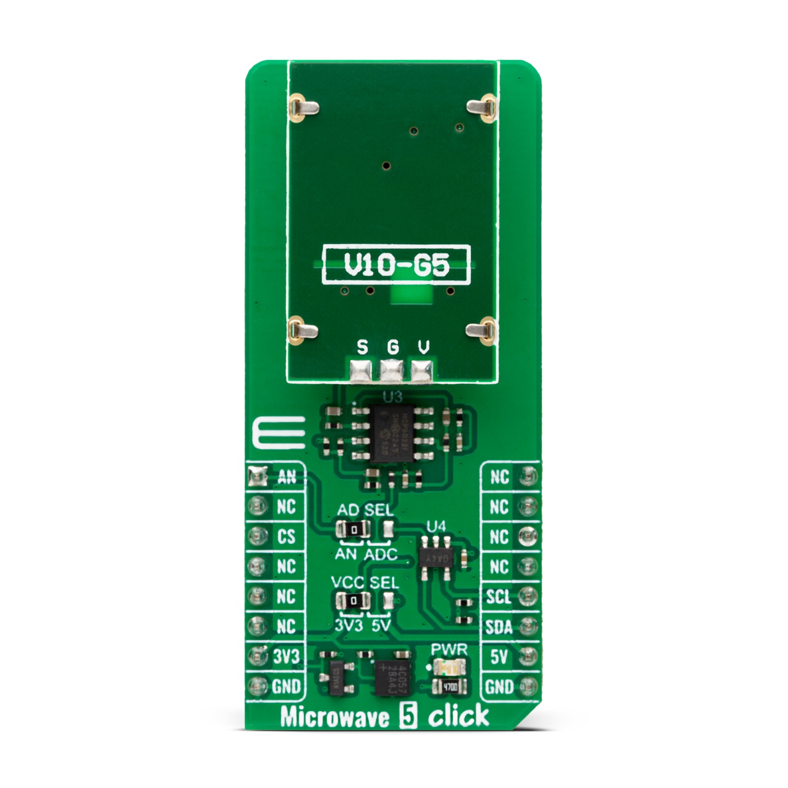
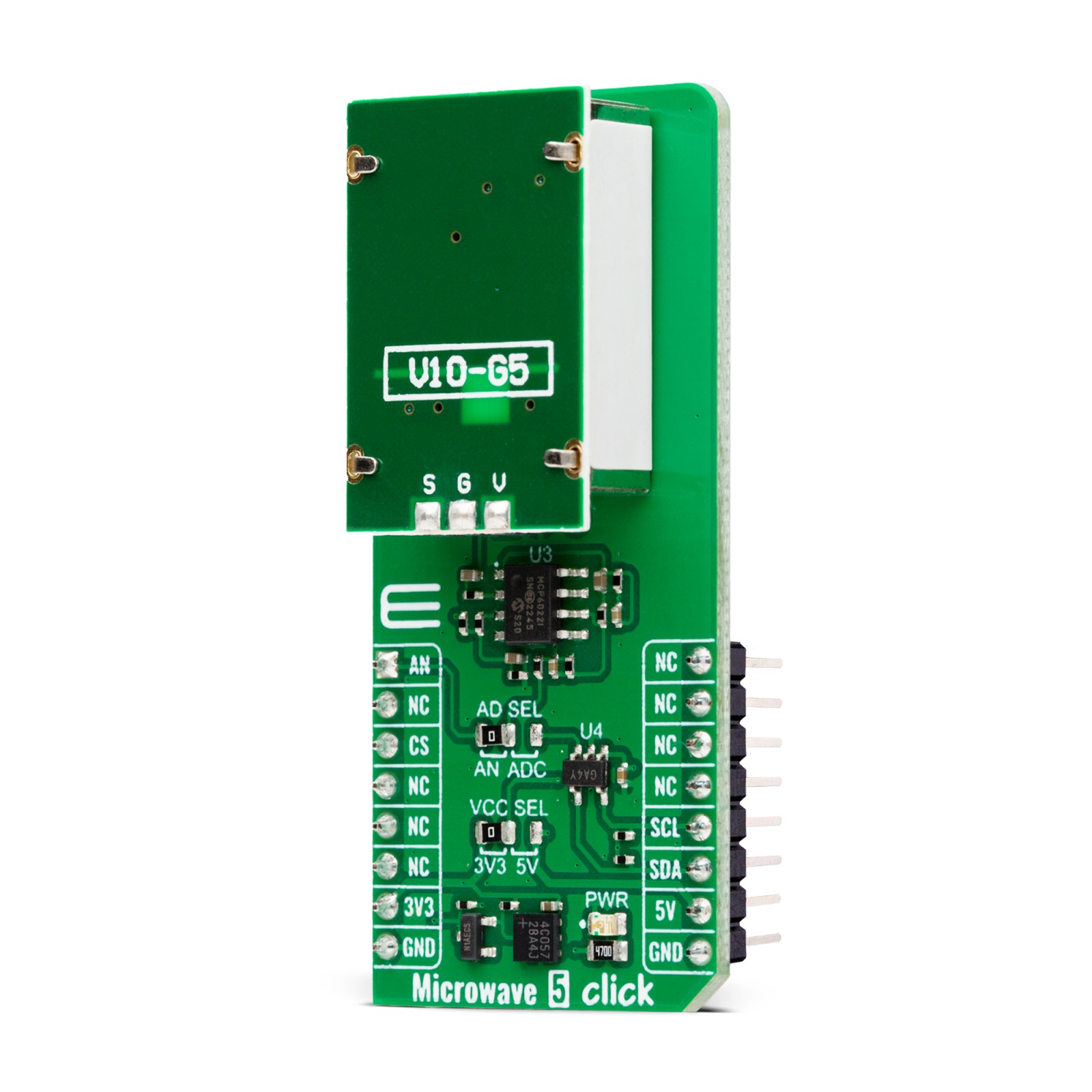
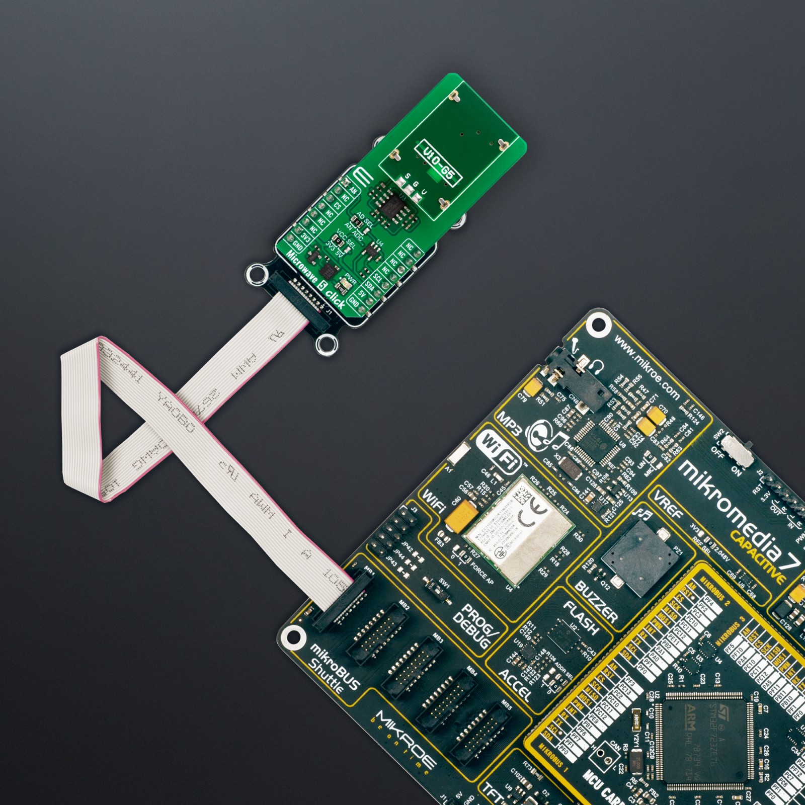
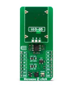
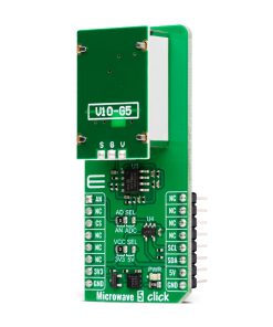
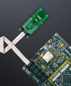
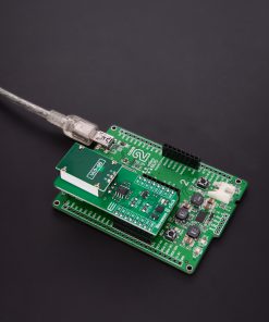
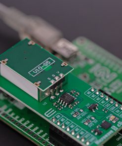
Microwave 5 Click is based on the PD-V10-G5, a miniature X-band microwave transceiver from Ningbo Pdlux Electronic Technology. This microwave solution is housed in a metal can and features a dielectric resonator stabilized oscillator, providing a stable operation over a broad temperature range in either CW or low-duty cycle pulse mode and an integrated homodyne receiver for enhanced sensitivity and reliability. The Microwave 5 Click detects the frequency shift between a transmitted and a received signal reflected from a moving object within the field of view of the transceiver. The standard antenna has 5dBi of gain and a minimum power output 5dBm with -84dBm of sensitivity for a 10dB signal-to-noise ratio.
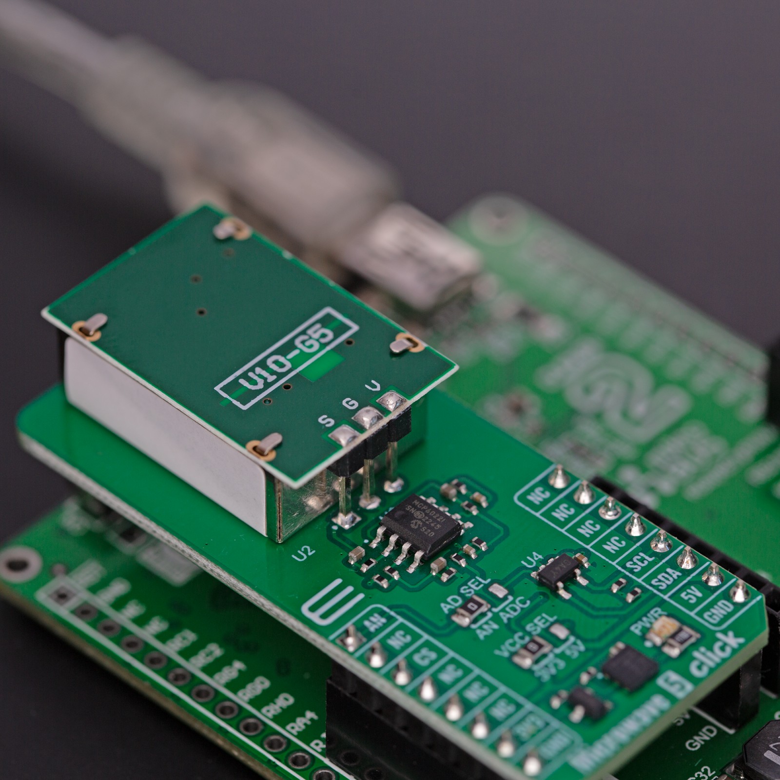
The produced low-level output is amplified over the MCP6022, a rail-to-rail input/output 10MHz operational amplifier from Microchip. The amplified output goes to the ADC SEL jumper, which allows you to read the data over an analog pin of the mikroBUS™ socket or the MCP3221, a low-power 12-bit A/D converter from Microchip. The jumper is set to an analog pin by default. If the option is the ADC, you can count up to 22.3 ksps in I2C fast mode.
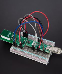
As mentioned, the Microwave 5 Click uses an analog AN pin of the mikroBUS™ socket or a standard 2-Wire I2C interface of the MCP3221 to communicate with the host MCU. The I2C of the ADC supports standard (100KHz) and fast (400KHz) modes. Depending on the ADC of the host MCU, the onboard 12-bit ADC could be a better choice. Worth noting is that the microwave sensor works on 5V.
This Click board™ can operate with either 3.3V or 5V logic voltage levels selected via the VCC SEL jumper. This way, both 3.3V and 5V capable MCUs can use the communication lines properly. This Click board™ comes equipped with a library containing easy-to-use functions and an example code that can be used, as a reference, for further development.
Specifications
Type
Motion
Applications
Can be used for the development of intrusion alarms, automatic door openers, presence-sensing applications, and more
On-board modules
PD-V10-G5 – miniature X-band microwave transceiver from Ningbo Pdlux Electronic Technology
Key Features
Low power consumption, low cost, high sensitivity, patch antenna, additional 12-bit analog-to-digital converter, up to 22.3 ksps, uses Doppler shift phenomenon to “sense” motion, and more
Interface
Analog,I2C
Feature
ClickID
Compatibility
mikroBUS™
Click board size
L (57.15 x 25.4 mm)
Input Voltage
3.3V or 5V
Pinout diagram
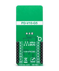
This table shows how the pinout on Microwave 5 Click corresponds to the pinout on the mikroBUS™ socket (the latter shown in the two middle columns).
Onboard settings and indicators
Label | Name | Default | Description |
---|---|---|---|
LD1 | PWR | – | Power LED Indicator |
JP1 | VCC SEL | Left | Logic Level Voltage Selection 3V3/5V: Left position 3V3, Right position 5V |
JP2 | ADC SEL | Right | Output Signal A/D Selection AN/ADC: Left position AN, Right position ADC |
Microwave 5 Click electrical specifications
Description | Min | Typ | Max | Unit |
---|---|---|---|---|
Supply Voltage | 3.3 | – | 5 | V |
Operating Frequency | – | 10.525 | – | GHz |
Sensitivity | – | -84 | – | dBm |
Software Support
We provide a library for the Microwave 5 Click as well as a demo application (example), developed using MIKROE compilers. The demo can run on all the main MIKROE development boards.
Package can be downloaded/installed directly from NECTO Studio Package Manager (recommended), downloaded from our LibStock™ or found on Mikroe github account.
Library Description
This library contains API for Microwave 5 Click driver.
Key functions
-
microwave5_read_raw_adc
Microwave 5 read raw ADC value function. -
microwave5_read_voltage
Microwave 5 read voltage level function. -
microwave5_set_vref
Microwave 5 set vref function.
Example Description
This example demonstrates the use of the Microwave 5 Click board™ by reading and displaying the results of AD conversion and motion detection.
void application_task ( void )
{
if ( MICROWAVE5_OK == microwave5_read_voltage( µwave5, &voltage ) )
{
if ( ( ( voltage + MICROWAVE5_THRESHOLD ) < reference ) ||
( ( voltage - MICROWAVE5_THRESHOLD ) > reference ) )
{
if ( MICROWAVE5_FLAG_SET == flag )
{
log_printf( &logger, " Motion detected!rn" );
log_printf( &logger, " Detector AN Voltage : %.3f[V]rn", voltage );
log_printf( &logger, "----------------------------------rn" );
flag = MICROWAVE5_FLAG_CLEAR;
Delay_ms( 100 );
}
}
else
{
flag = MICROWAVE5_FLAG_SET;
}
}
}
The full application code, and ready to use projects can be installed directly from NECTO Studio Package Manager (recommended), downloaded from our LibStock™ or found on Mikroe github account.
Other Mikroe Libraries used in the example:
- MikroSDK.Board
- MikroSDK.Log
- Click.Microwave5
Additional notes and informations
Depending on the development board you are using, you may need USB UART click, USB UART 2 Click or RS232 Click to connect to your PC, for development systems with no UART to USB interface available on the board. UART terminal is available in all MIKROE compilers.
mikroSDK
This Click board™ is supported with mikroSDK – MIKROE Software Development Kit. To ensure proper operation of mikroSDK compliant Click board™ demo applications, mikroSDK should be downloaded from the LibStock and installed for the compiler you are using.
For more information about mikroSDK, visit the official page.