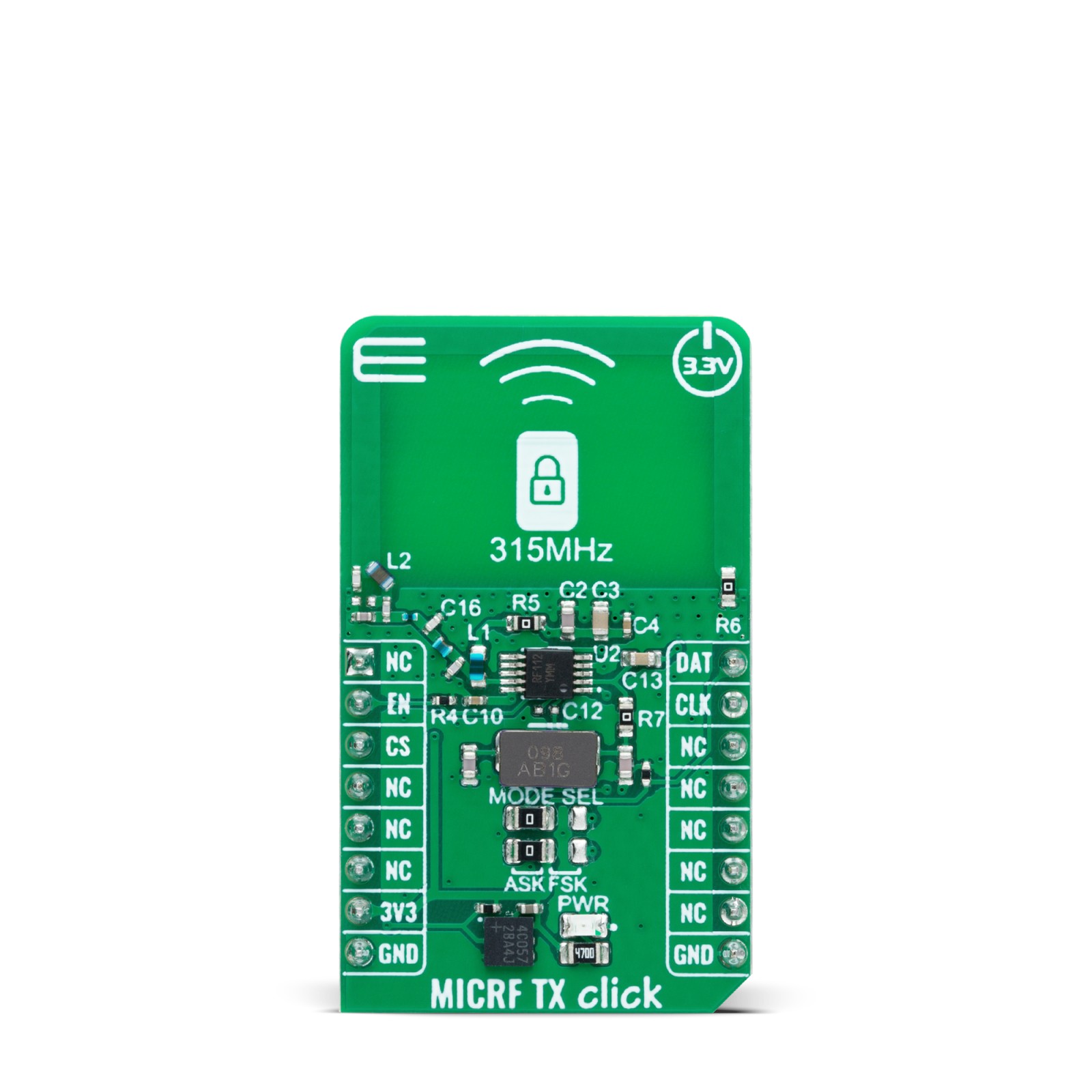
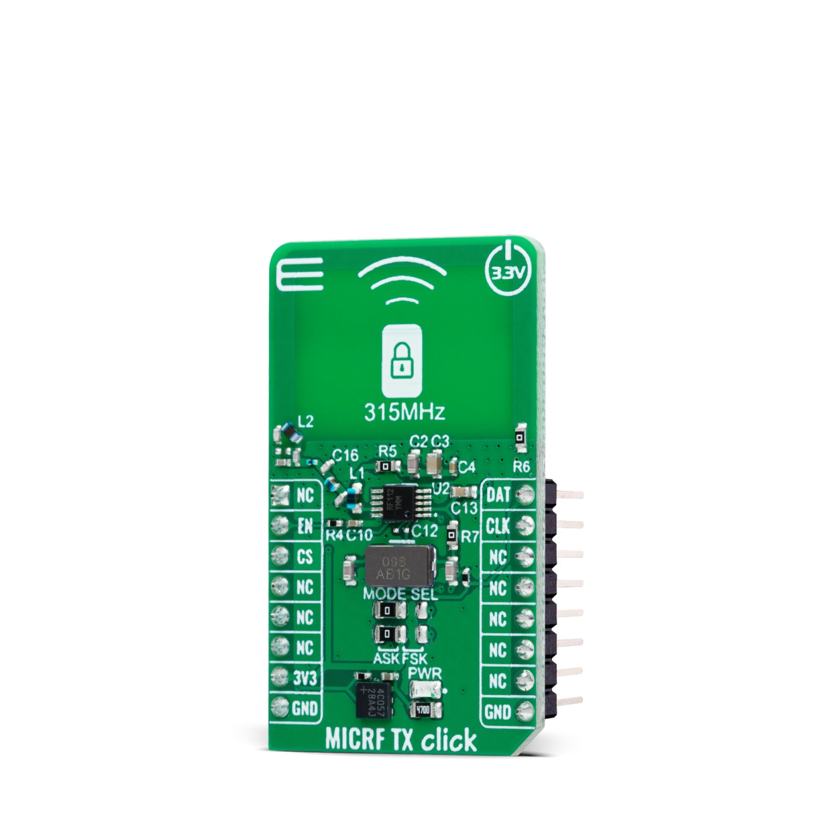
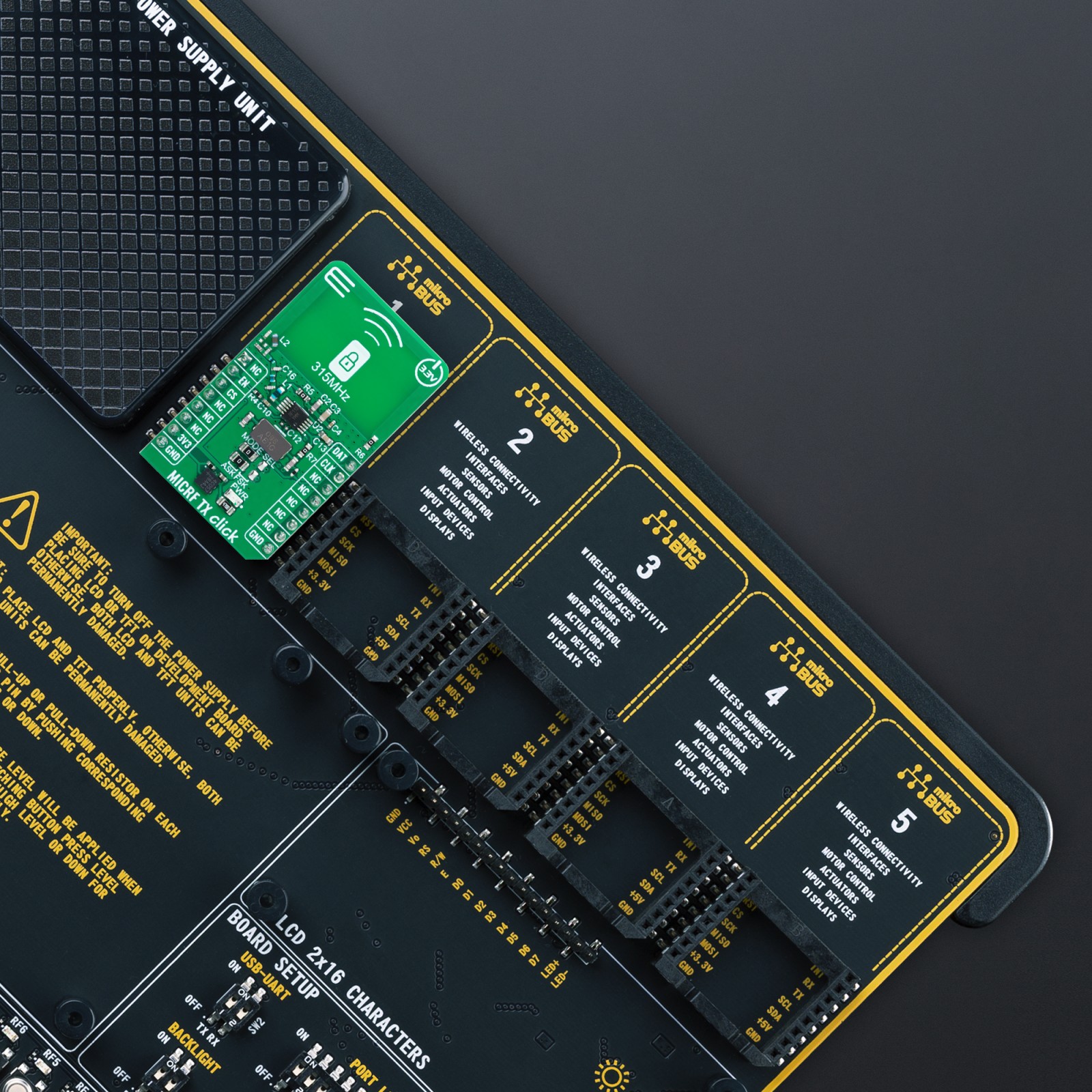
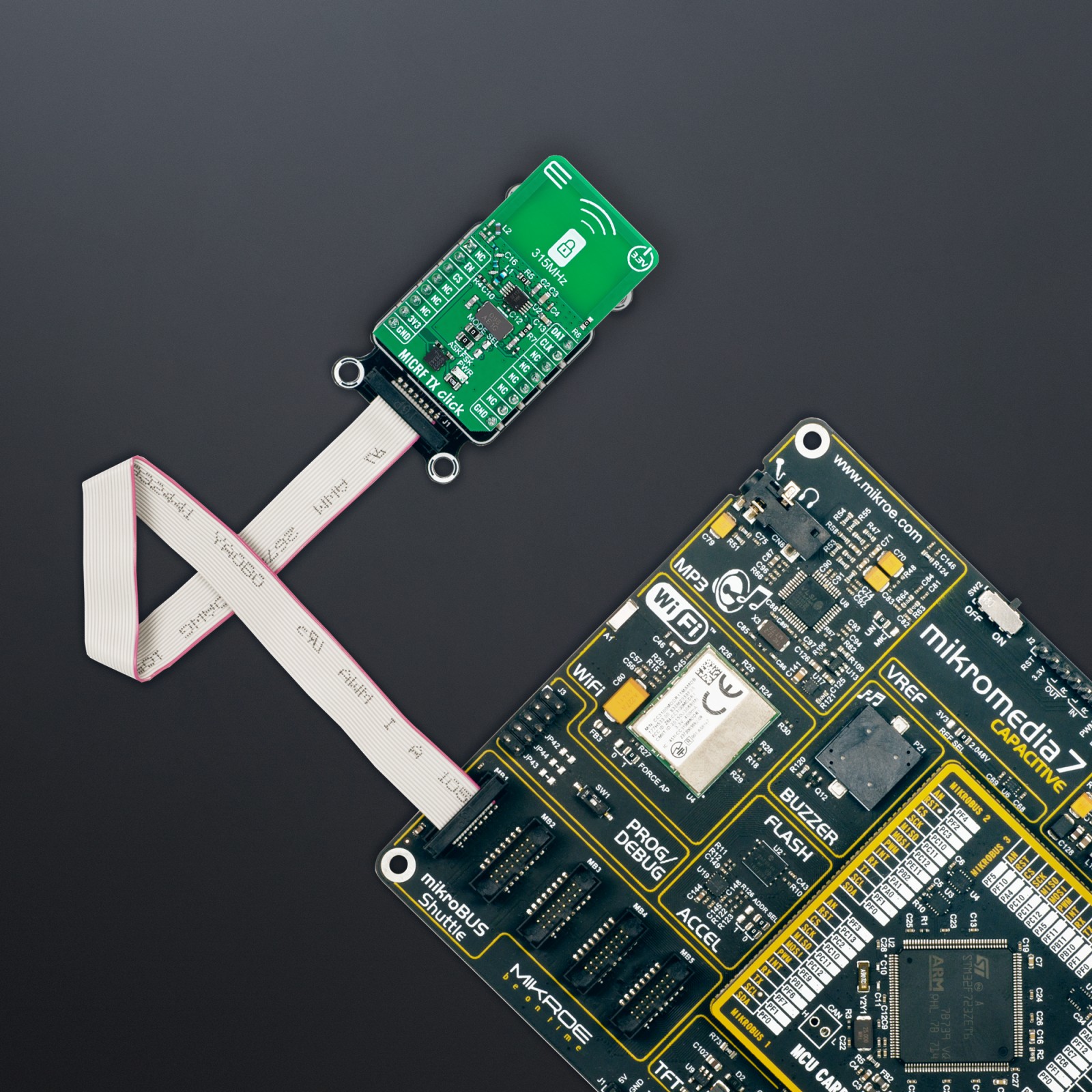
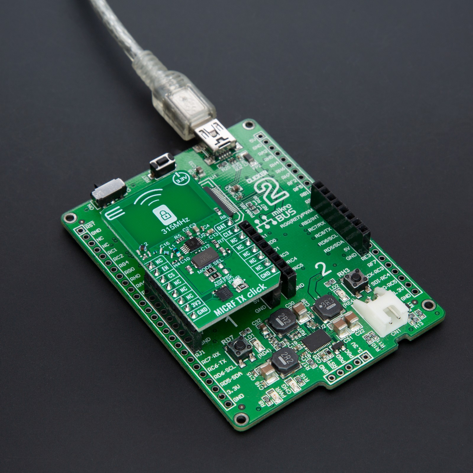
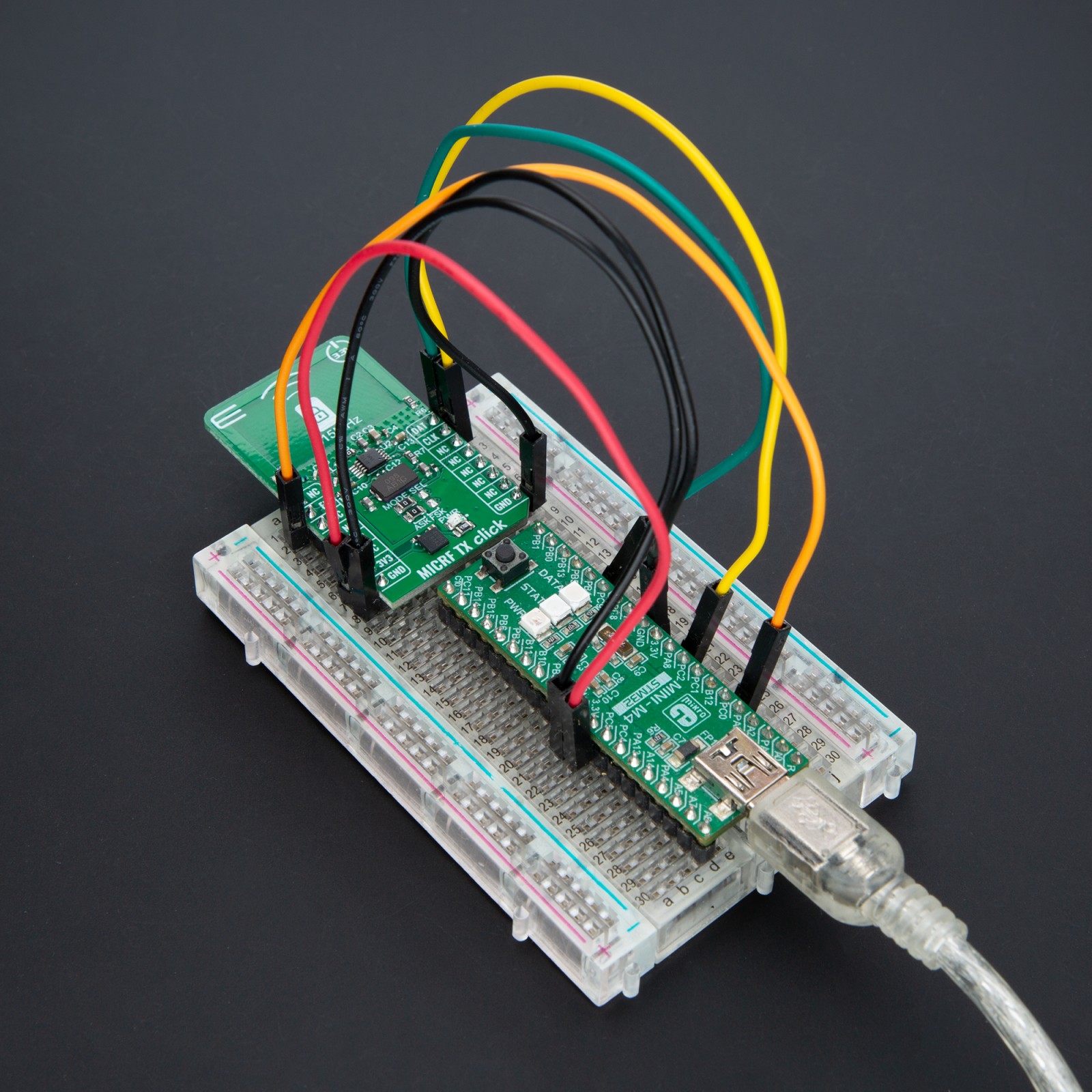
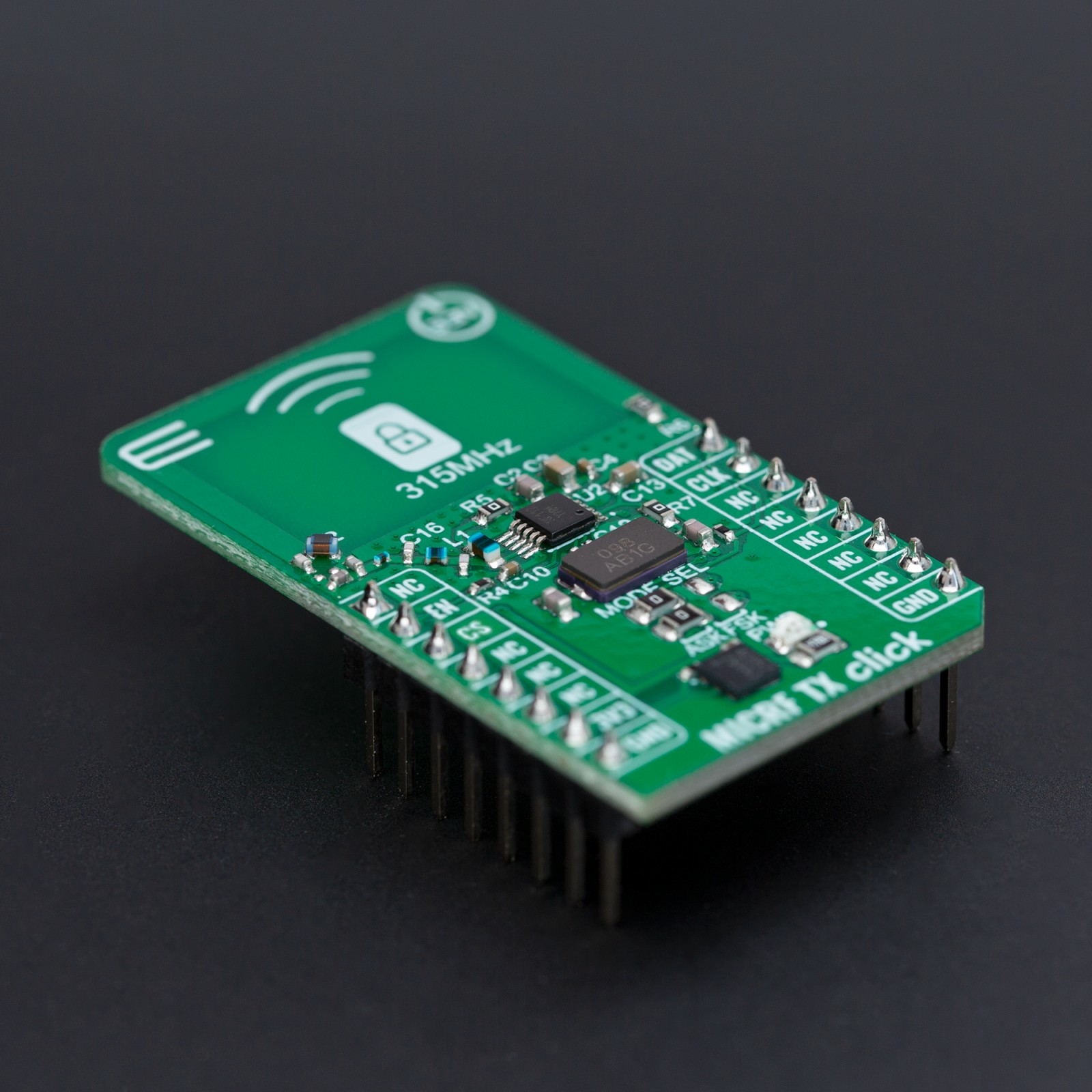
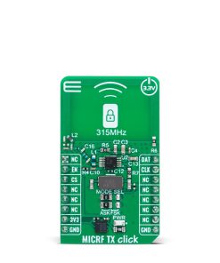
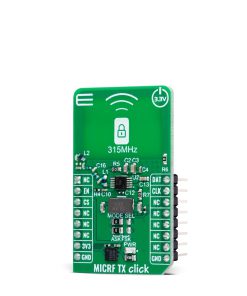
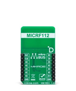
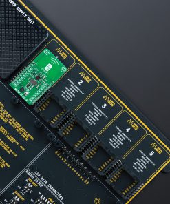
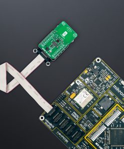
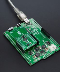
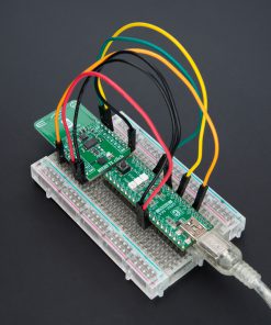
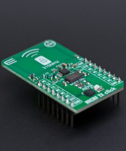
NOTE: Pair the MICRF TX Click with the MICRF RX Click for optimal performance, as both boards are designed to work on the 315MHz frequency. Perfect for developers looking for compatible transmitter and receiver units. Find both Click boards™ available for purchase at the MIKROE shop.
How does it work?
MICRF TX Click is based on the MICRF112, an RF transmitter IC from Microchip. This high-performance IC is designed for simplicity in operation, functioning on a “Data-In, RF-Out” basis. It supports both Amplitude Shift Keying (ASK) and Frequency Shift Keying (FSK) modulation types and incorporates a Phase-Locked Loop (PLL) for reliable frequency stabilization. Specifically made for the 315MHz band, the MICRF112 requires only a basic crystal oscillator – such as the onboard 9.84375MHz crystal – to accurately establish its operating frequency alongside minimal external components to match the power amplifier’s output with the antenna. It is ideally used in various applications like Remote Keyless Entry (RKE) systems, various remote controls (for set-top boxes, HVAC systems, and appliances), Garage Door Openers (GDO), Tire Pressure Monitoring Systems (TPMS), outdoor weather stations, and systems for security, alarm, lighting and fan control, doorbells, irrigation, and more.
Concerning the board’s connectivity with an MCU, this board uses several pins on the mikroBUS™ socket. The EN pin functions as a chip enable function for toggling the device ON or OFF state. The DAT pin accepts modulation data input (either ASK or FSK, determined by the MODE SEL jumper’s setting) directly. In case of FSK modulation, an additional capacitor like C12 is required between the XTLOUT and XTAL_MOD pins of the MICRF112 (C12 not populated by default). If the user desires a different frequency instead of the onboard oscillator, they should desolder the R7 resistor on the board, thereby disconnecting the onboard oscillator. Then, a 1nF capacitor should be soldered in place of C13 capacitor, and the CLK pin is then used as the reference oscillator input.
Operating with a 3.3V input from the mikroBUS™ power supply, the MICRF112 can generate a continuous wave (CW) output power of +10dBm into a 50Ω antenna load. It also boasts an energy-efficient shutdown mode, drawing a mere 50nA, making it highly suitable for battery-dependent devices.
This Click board™ can be operated only with a 3.3V logic voltage level. The board must perform appropriate logic voltage level conversion before using MCUs with different logic levels. Also, it comes equipped with a library containing functions and an example code that can be used as a reference for further development.
Specifications
Type
Sub-1 GHz Transceievers
Applications
Ideal for Remote Keyless Entry (RKE) systems, various remote controls (for set-top boxes, HVAC systems, and appliances), Garage Door Openers (GDO), Tire Pressure Monitoring Systems (TPMS), outdoor weather stations, and systems for security, alarm, lighting and fan control, doorbells, irrigation, and more
On-board modules
MICRF112 – high-performance RF transmitter IC from Microchip
Key Features
Designed for 315MHz, support both ASK and FSK modulation, PLL for accurate frequency stabilization, 10dBm output power, low-power shutdown mode, chip enable control, and more
Interface
GPIO
Feature
ClickID
Compatibility
mikroBUS™
Click board size
M (42.9 x 25.4 mm)
Input Voltage
3.3V
Pinout diagram
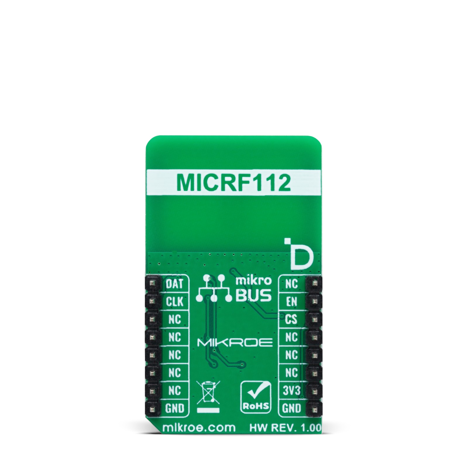
This table shows how the pinout on MICRF TX Click corresponds to the pinout on the mikroBUS™ socket (the latter shown in the two middle columns).
Onboard settings and indicators
Label | Name | Default | Description |
---|---|---|---|
LD1 | PWR | – | Power LED Indicator |
JP1-JP2 | MODE SEL | Left | Modulation Selection ASK/FSK: Left position ASK, Right position FSK |
MICRF TX Click electrical specifications
Description | Min | Typ | Max | Unit |
---|---|---|---|---|
Supply Voltage | – | 3.3 | – | V |
Transmitter Frequency Range | – | 315 | – | MHz |
Output Power | – | +10 | – | dBm |
Software Support
We provide a library for the MICRF TX Click as well as a demo application (example), developed using MIKROE compilers. The demo can run on all the main MIKROE development boards.
Package can be downloaded/installed directly from NECTO Studio Package Manager(recommended), downloaded from our LibStock™ or found on Mikroe github account.
Library Description
This library contains API for MICRF TX Click driver.
Key functions
micrftx_send_data
This function builds and sends a packet of data. The packet format is as follows (MSB first, manchester IEEE 802.3): MICRFTX_TRAINING_BYTES, PREABMLE, LEN, DATA_IN, CRC16 (calculated from whole packet excluding training bytes).
Example Description
This example demonstrates the use of MICRF TX click board by sending a predefined message to the receiver.
void application_task ( void )
{
log_printf ( &logger, " Sending data: %srnn", ( char * ) MICRFTX_MESSAGE );
micrftx_send_data ( &micrftx, MICRFTX_PREAMBLE, MICRFTX_MESSAGE, strlen ( MICRFTX_MESSAGE ) );
Delay_ms ( 3000 );
}
The full application code, and ready to use projects can be installed directly from NECTO Studio Package Manager(recommended), downloaded from our LibStock™ or found on Mikroe github account.
Other Mikroe Libraries used in the example:
- MikroSDK.Board
- MikroSDK.Log
- Click.MICRFTX
Additional notes and informations
Depending on the development board you are using, you may need USB UART click, USB UART 2 Click or RS232 Click to connect to your PC, for development systems with no UART to USB interface available on the board. UART terminal is available in all MIKROE compilers.
mikroSDK
This Click board™ is supported with mikroSDK – MIKROE Software Development Kit. To ensure proper operation of mikroSDK compliant Click board™ demo applications, mikroSDK should be downloaded from the LibStock and installed for the compiler you are using.
For more information about mikroSDK, visit the official page.