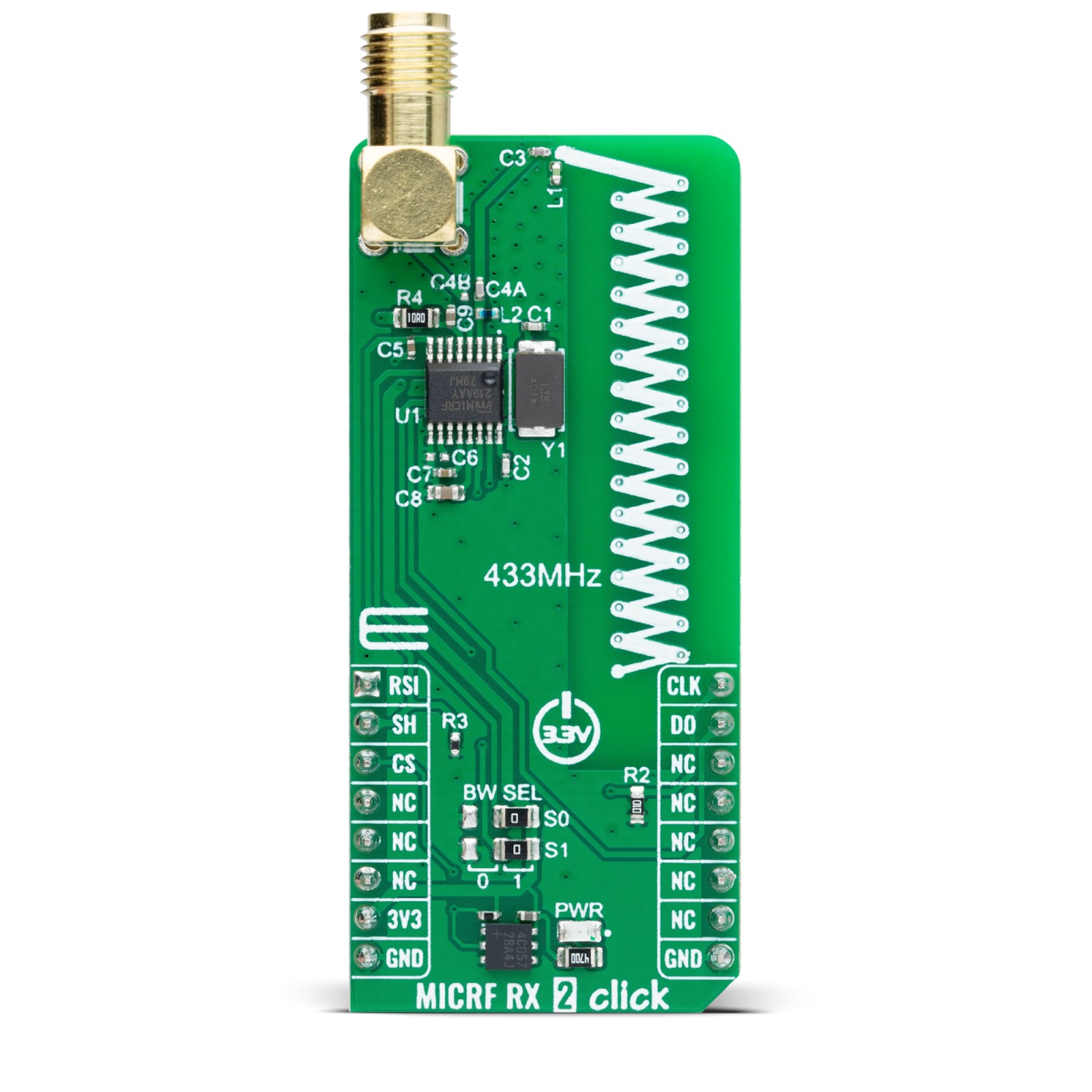
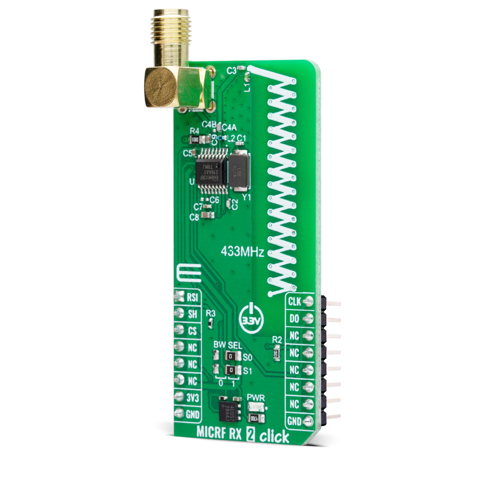
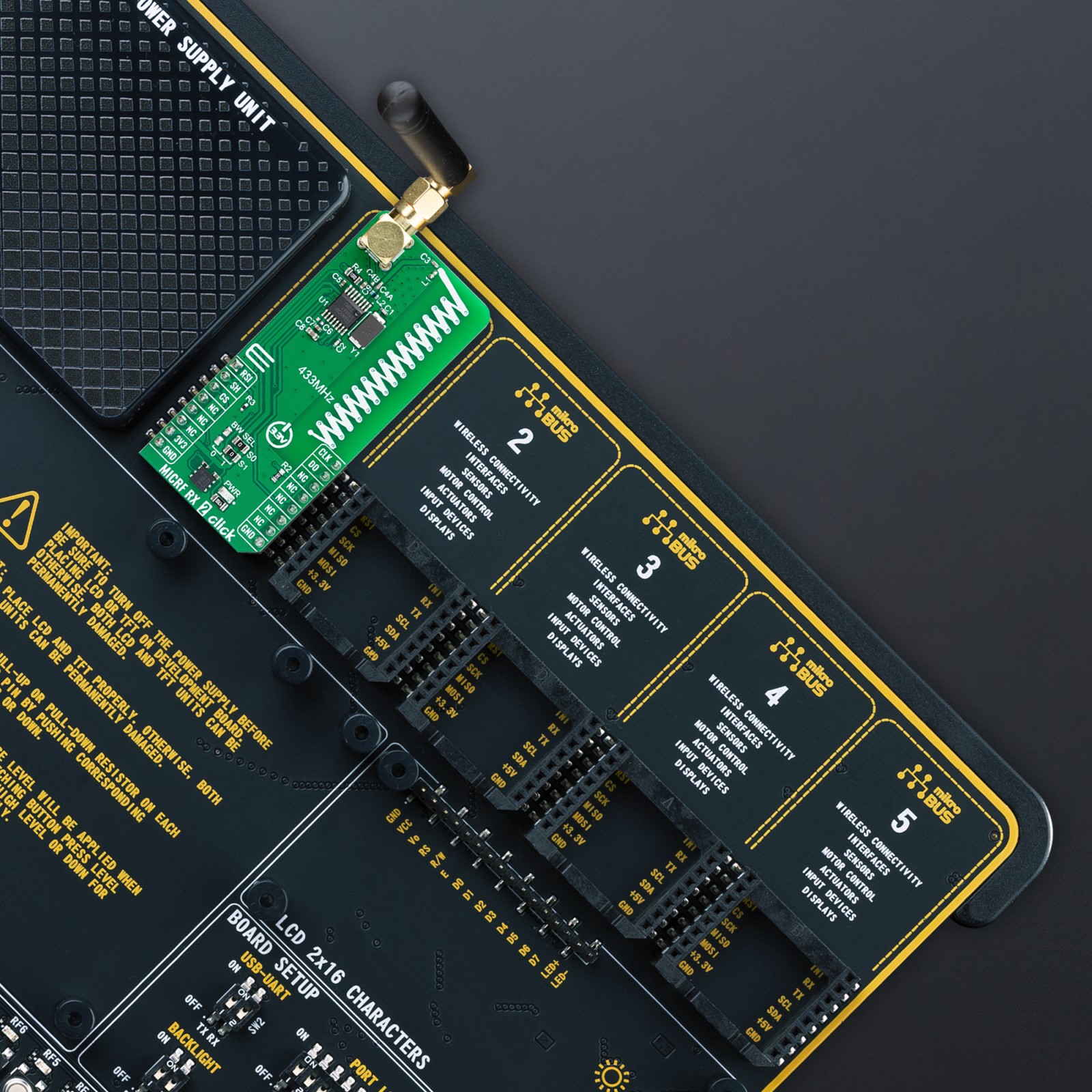
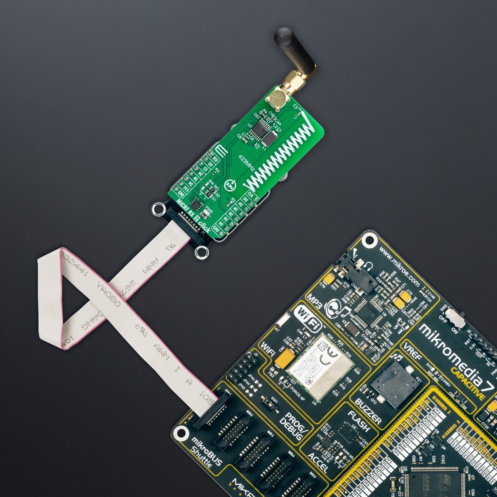
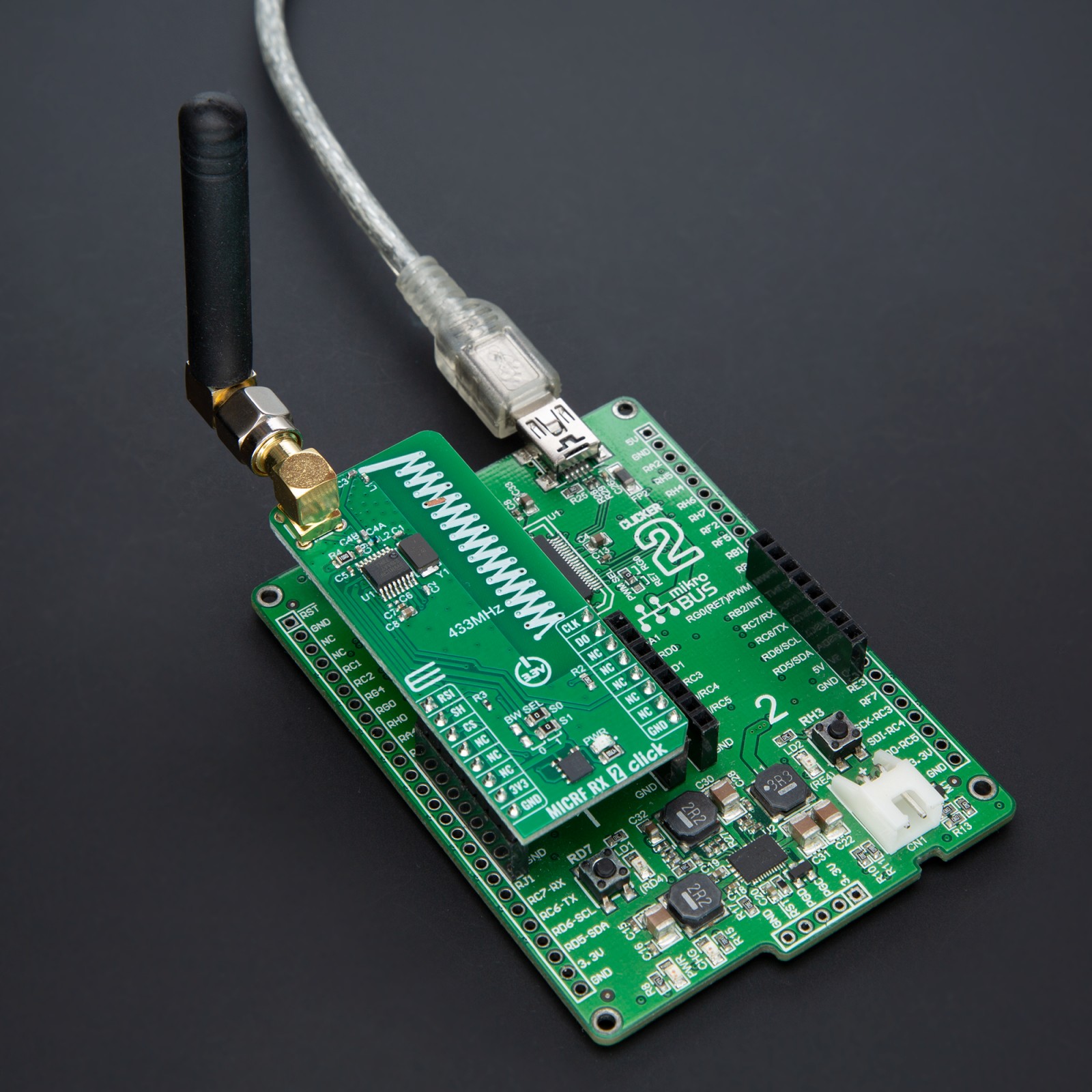
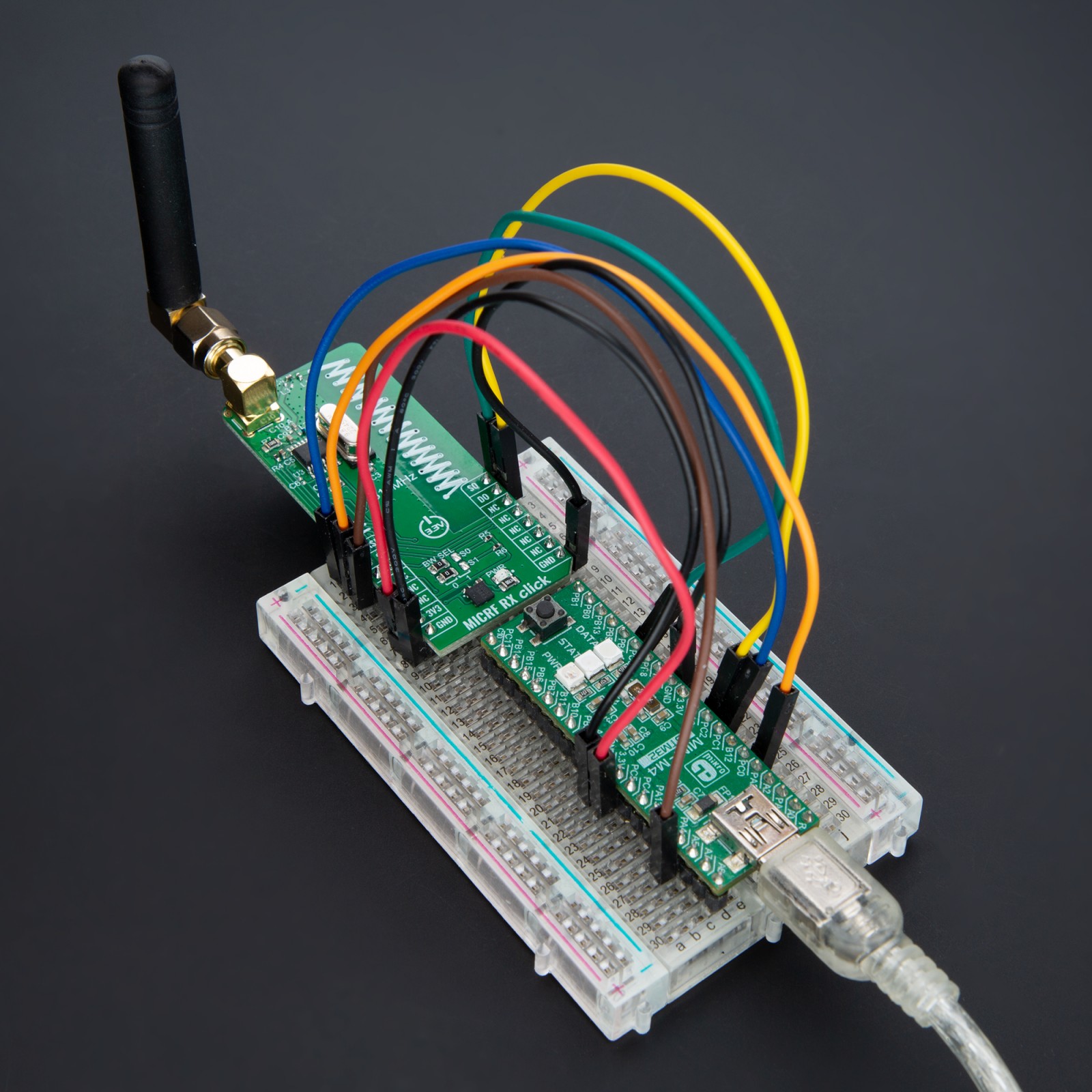
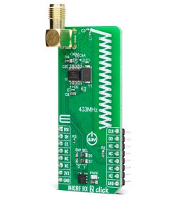
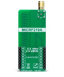
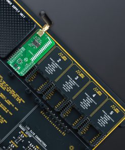
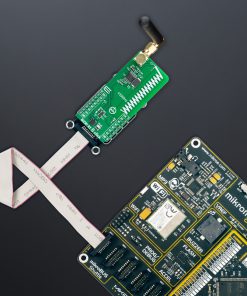
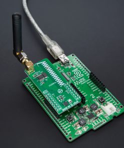
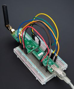
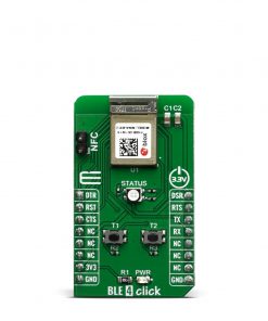
NOTE: Pair the MICRF RX 2 Click with the OOK TX Click for optimal performance, as both boards are designed to work on the 433MHz frequency. Perfect for developers looking for compatible transmitter and receiver units. Find both Click boards™ available for purchase at the MIKROE shop.
How does it work?
MICRF RX 2 Click is based on the MICRF219A, an ASK/OOK receiver with Auto-Poll and RSSI from Microchip. This super-heterodyne, image-reject RF receiver is engineered to require only a crystal, in this case, an onboard 13.52313MHz, and a minimal set of external components for operation. As mentioned, the MICRF219A can be programmed into an Auto-polling mode via register configuration. In this mode, it monitors if there is a valid incoming RF signal while holding data output (DO pin) in a LOW logic state. In this mode, the MICRF219A also goes between the sleep and polling states. Its suitability spans across various applications, such as low-power Remote Keyless Entry (RKE), Tire Pressure Monitoring Systems (TPMS), and remote actuation systems.
In terms of performance, the MICRF219A distinguishes itself with a sensitivity of -110dBm at 1kbps and a 0.1% Bit Error Rate (BER), complemented by four selectable demodulator filter bandwidths ranging from 1625Hz to 13kHz. Filter bandwidth can be selected by placing BW SEL jumpers in a corresponding position, 0 or 1, choosing the corresponding frequency based on the truth table from the attached MICRF219A datasheet (Table 1.). This feature permits the device to accommodate bit rates as high as 20kbps (from 2.5kbps up to 20kbps). Operating on a 3.3V supply from the mikroBUS™ power rail, it is optimized for 433MHz operation, drawing a typical supply current of 6mA.
The MICRF219A also has a low-power shutdown mode controllable through the SH pin, reducing the supply current to an impressive 0.1µA, alongside an RSI pin to indicate received signal strength. Besides these pins, it also uses the mentioned DO pin as its demodulated data output pin and the CLK pin as the programmed clock input pin for programming the device in combination with the DO pin.
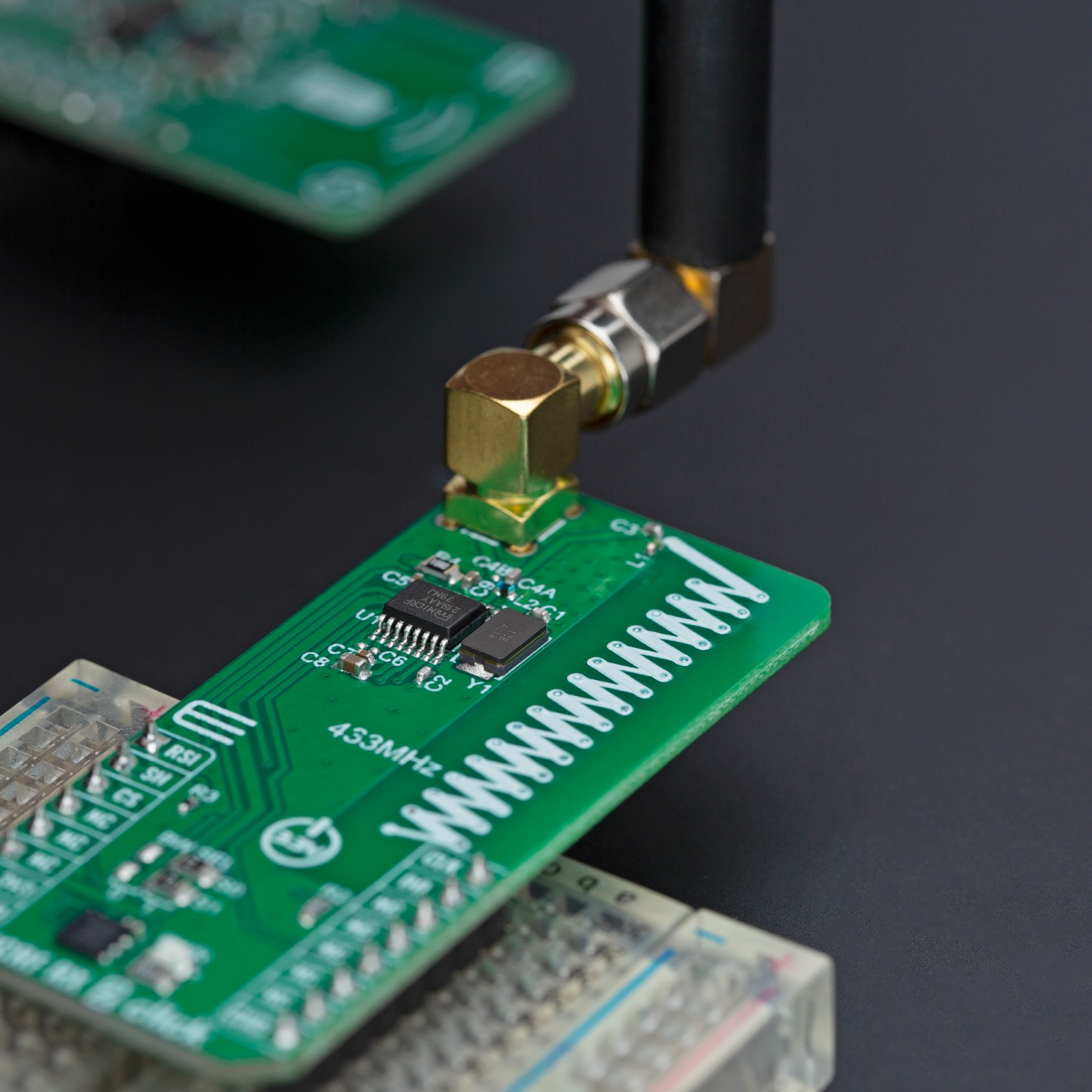
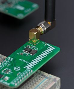
For antenna configurations, the board allows for the use of an onboard PCB antenna specifically tuned to 433MHz or an external antenna like Rubber Angle 433MHz Antenna via an SMA connector, with the selection made possible by adjusting the capacitor C4 from position A to B near the SMA connector.
This Click board™ can be operated only with a 3.3V logic voltage level. The board must perform appropriate logic voltage level conversion before using MCUs with different logic levels. Also, it comes equipped with a library containing functions and an example code that can be used as a reference for further development.
Specifications
Type
Sub-1 GHz Transceievers
Applications
Ideal for remote keyless entry, tire pressure monitoring systems, and remote actuation systems
On-board modules
MICRF219A – ASK/OOK receiver with Auto-Poll and RSSI from Microchip
Key Features
High performance RF receiver, ASK/OOK modulation, optimized for 433MHz, high sensitivity, adjustable demodulator filter bandwidth, low-power shutdown mode, Auto-polling, internal/external antenna selection, received signal strength indicator, and more
Interface
GPIO
Feature
ClickID
Compatibility
mikroBUS™
Click board size
L (57.15 x 25.4 mm)
Input Voltage
3.3V
Pinout diagram
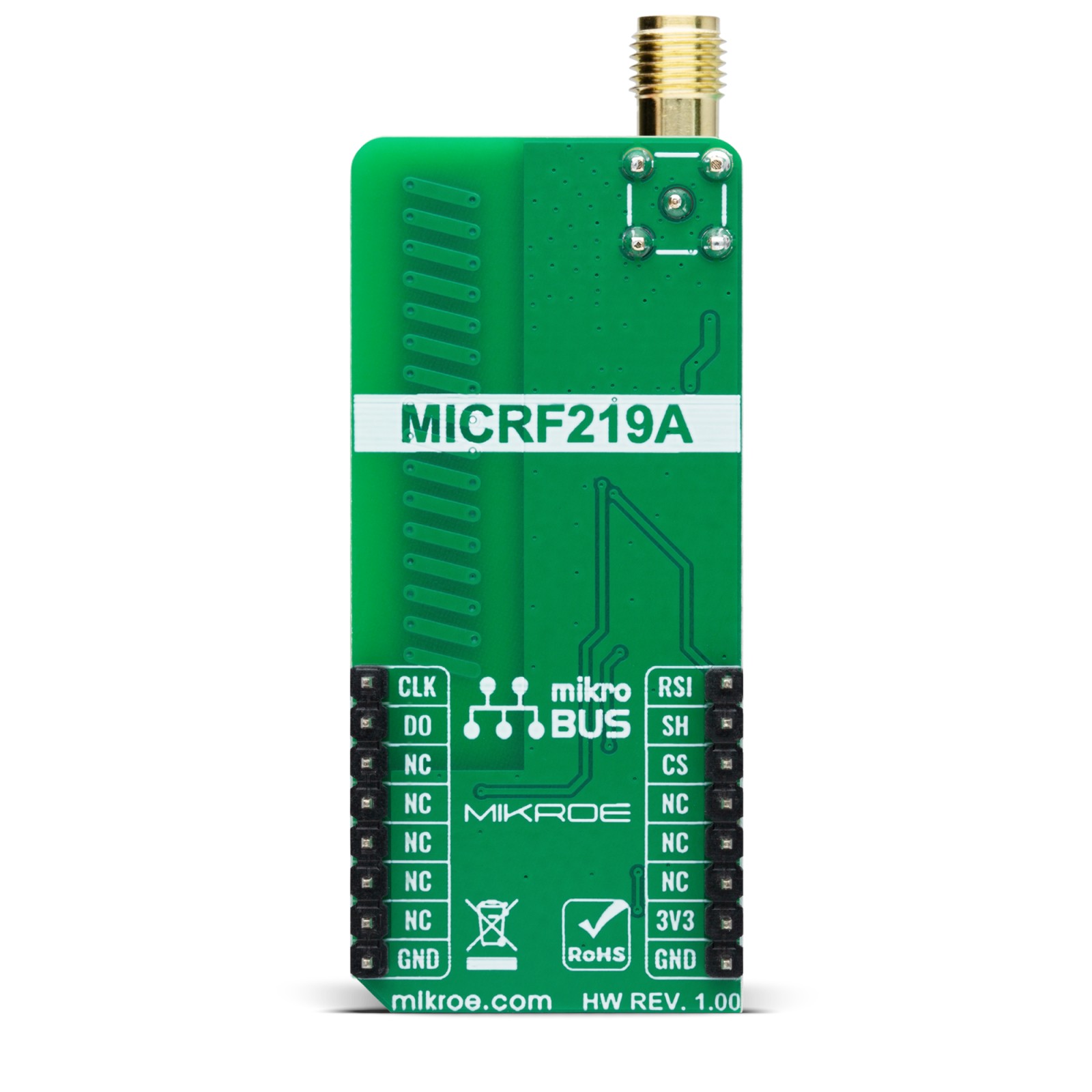
This table shows how the pinout on MICRF RX 2 Click corresponds to the pinout on the mikroBUS™ socket (the latter shown in the two middle columns).
Onboard settings and indicators
Label | Name | Default | Description |
---|---|---|---|
LD1 | PWR | – | Power LED Indicator |
JP1-JP2 | BW SEL | Right | Demodulation Bandwidth Selection 0/1: Left position 0, Right position 1 |
MICRF RX 2 Click electrical specifications
Description | Min | Typ | Max | Unit |
---|---|---|---|---|
Supply Voltage | – | 3.3 | – | V |
Receiver Frequency Range | – | 433 | – | MHz |
Software Support
We provide a library for the MICRF RX 2 Click as well as a demo application (example), developed using MIKROE compilers. The demo can run on all the main MIKROE development boards.
Package can be downloaded/installed directly from NECTO Studio Package Manager(recommended), downloaded from our LibStock™ or found on Mikroe github account.
Library Description
This library contains API for MICRF RX 2 Click driver.
Key functions
-
micrfrx2_enable_device
This function enables device by setting the SHD pin to low logic state. -
micrfrx2_wait_ready
This function waits for all training bytes to arrive which indicates data ready. -
micrfrx2_read_packet
This function reads data packet and stores it in a packet_buf only if the MICRFRX2_PREAMBLE bytes are received successfully.
Example Description
This example demonstrates the use of MICRF RX 2 click board by reading and parsing packet messages received from the transmitter.
void application_task ( void )
{
static float rssi_v = 0;
static uint8_t packet_len = 0;
static uint8_t msg_cnt = 0;
static uint16_t crc = 0;
log_printf( &logger, "rn Waiting for data ready...rn" );
micrfrx2_wait_ready ( &micrfrx2 );
packet_len = micrfrx2_read_packet ( &micrfrx2 );
if ( packet_len )
{
micrfrx2_read_rssi_voltage ( &micrfrx2, &rssi_v );
crc = ( ( uint16_t ) packet_buf[ packet_len - 2 ] << 8 ) | packet_buf[ packet_len - 1 ];
if ( crc == micrftx2_calculate_crc16 ( packet_buf, packet_len - 2 ) )
{
log_printf( &logger, " Received message: " );
for ( msg_cnt = 0; msg_cnt < packet_buf[ 2 ]; msg_cnt++ )
{
log_printf( &logger, "%c", ( uint16_t ) packet_buf[ msg_cnt + 3 ] );
}
log_printf( &logger, "rn RSSI: %.1f dBmrn", MICRFRX2_RSSI_V_TO_DBM ( rssi_v ) );
}
}
Delay_ms ( 100 );
}
The full application code, and ready to use projects can be installed directly from NECTO Studio Package Manager(recommended), downloaded from our LibStock™ or found on Mikroe github account.
Other Mikroe Libraries used in the example:
- MikroSDK.Board
- MikroSDK.Log
- Click.MICRFRX2
Additional notes and informations
Depending on the development board you are using, you may need USB UART click, USB UART 2 Click or RS232 Click to connect to your PC, for development systems with no UART to USB interface available on the board. UART terminal is available in all MIKROE compilers.
mikroSDK
This Click board™ is supported with mikroSDK – MIKROE Software Development Kit. To ensure proper operation of mikroSDK compliant Click board™ demo applications, mikroSDK should be downloaded from the LibStock and installed for the compiler you are using.
For more information about mikroSDK, visit the official page.