How does it work?
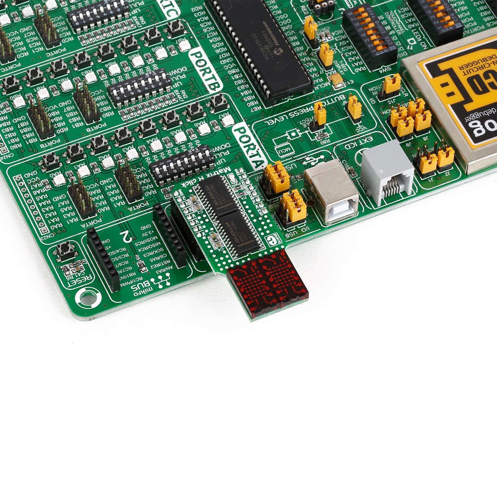
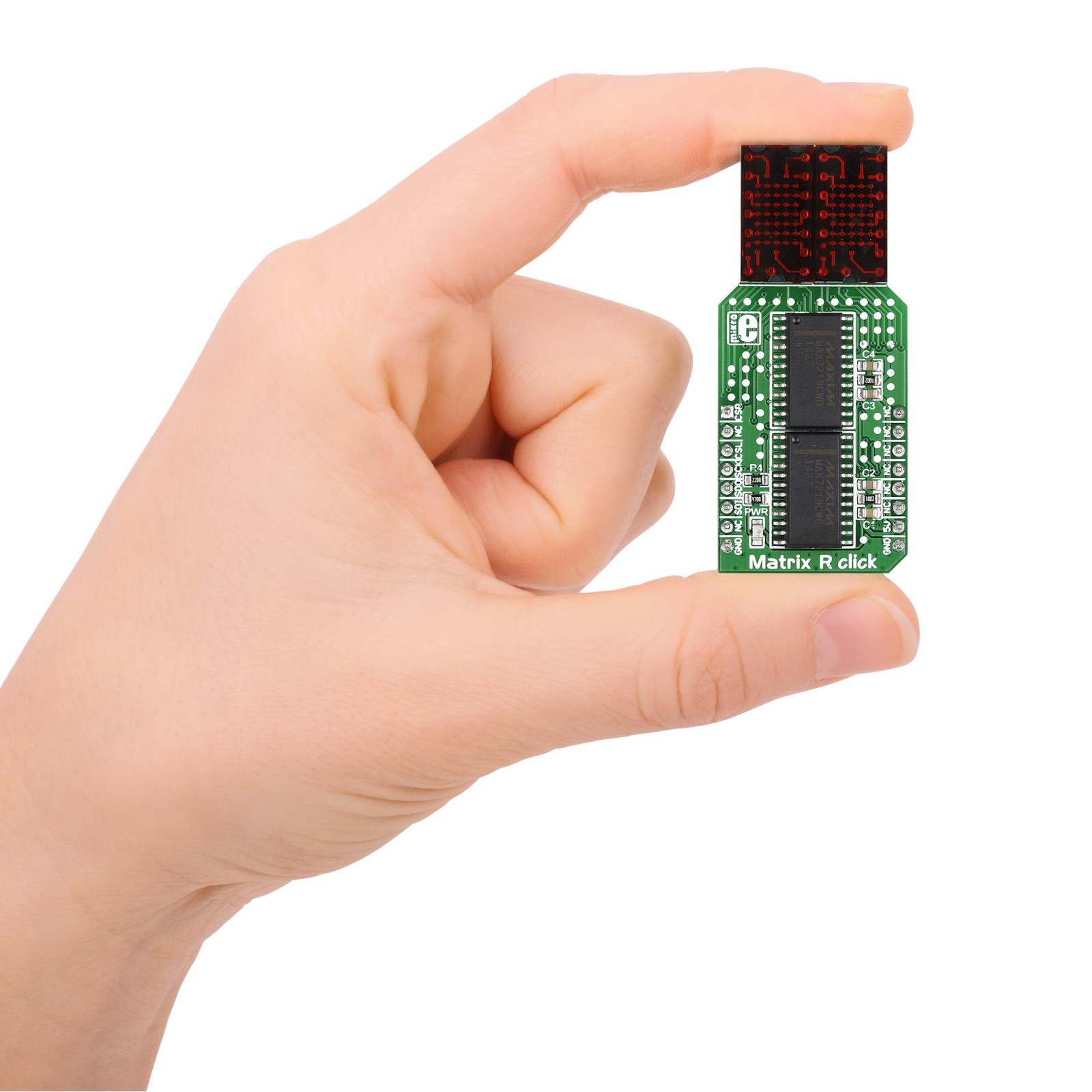
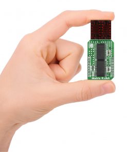
Matrix R Click is based on two MAX7219, serially interfaced, 8-digit LED display drivers from Analog Devices. The MAX7219 over 10MHz serial interface is capable of addressing each LED of the two onboard red 5×7 matrices individually or all at the same time. It has digital and analog brightness control, blanked display on Power-Up sequence, low-power shutdown with data retained, and more features. It also includes a BCD code-B decoder, multiplex scan circuitry, segment and digit drivers, and an 8×8 static RAM that stores each data. Users can get four-character displays if they double up on a board with two adjacent mikroBUS™ sockets, such as Fusion, Clicker 2, or Flip&Click.
The Matrix R Click uses an SPI serial interface to communicate to the host microcontroller, with speeds of up to 10MHz. Each MAX7219’s chip select pin is connected to the appropriate pin on the mikroBUS™ socket. The MAX7219 that controls the left display is connected to the pin labeled CSL, while the right is connected to the pin labeled CSR. Serial data is loaded into the shift register while the corresponding chip select pin is in a low logic state. The peak segment current is set to around 40mA with an external resistor. The display’s brightness can be controlled by the internal PWM by the software.
This Click board™ can be operated only with a 5V logic voltage level. The board must perform appropriate logic voltage level conversion before using MCUs with different logic levels. However, the Click board™ comes equipped with a library containing functions and an example code that can be used, as a reference, for further development.
Specifications
Type
LED Matrix
Applications
Can be used for the development of user interfaces, graphical displays of information, and similar applications that display clearly visible low-resolution graphics or text
On-board modules
MAX7219 – serially interfaced, 8-digit LED display drivers from Analog Devices
Key Features
Pair of 7×5 LED matrices, pair of MAX7219 8-digit LED display drivers, drivers control each LED of the matrices individually, or all at the same time, brightness control, blank on Power-Up, low power consumption, high performance, and more
Interface
GPIO,SPI
Feature
No ClickID
Compatibility
mikroBUS™
Click board size
L (57.15 x 25.4 mm)
Input Voltage
5V
Pinout diagram
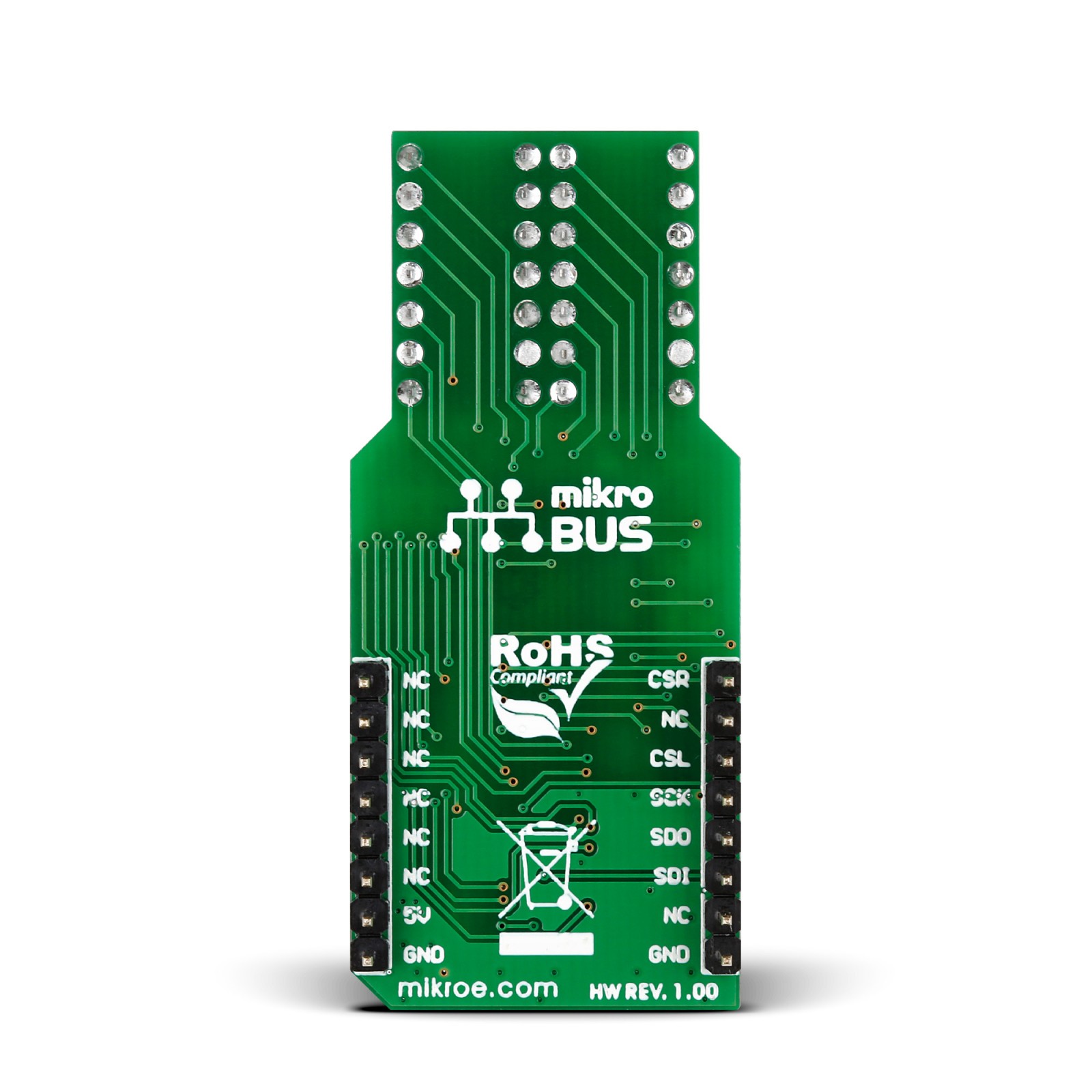
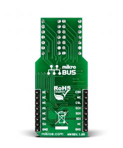
This table shows how the pinout on Matrix R Click corresponds to the pinout on the mikroBUS™ socket (the latter shown in the two middle columns).
Onboard settings and indicators
Label | Name | Default | Description |
---|---|---|---|
LD1 | PWR | – | Power LED Indicator |
Matrix R Click electrical specifications
Description | Min | Typ | Max | Unit |
---|---|---|---|---|
Receiver inputs voltage range | – | 5 | – | V |
Software Support
We provide a library for the Matrix R Click as well as a demo application (example), developed using MIKROE compilers. The demo can run on all the main MIKROE development boards.
Package can be downloaded/installed directly from NECTO Studio Package Manager (recommended), downloaded from our LibStock™ or found on Mikroe github account.
Library Description
This library contains API for Matrix R Click driver.
Key functions
-
matrixr_display_characters
This function displays the specified characters on the L/R segments of the click. -
matrixr_set_csn_high
This function sets the CSN pin output to high. -
matrixr_set_csn_low
This function sets the CSN pin output to low.
Example Description
This example showcases how to prepare the logger and click modules for use and how to display ASCII characters on both of the LED segments of the click.
void application_task ( ) {
matrixr_display_characters( &matrixr, ' ', 'M' );
Delay_ms( 1000 );
matrixr_display_characters( &matrixr, 'M', 'i' );
Delay_ms( 1000 );
matrixr_display_characters( &matrixr, 'i', 'k' );
Delay_ms( 1000 );
matrixr_display_characters( &matrixr, 'k', 'r' );
Delay_ms( 1000);
matrixr_display_characters( &matrixr, 'r', 'o' );
Delay_ms( 1000 );
matrixr_display_characters( &matrixr, 'o', 'E' );
Delay_ms( 1000 );
matrixr_display_characters( &matrixr, 'E', 'l' );
Delay_ms( 1000 );
matrixr_display_characters( &matrixr, 'l', 'e' );
Delay_ms( 1000 );
matrixr_display_characters( &matrixr, 'e', 'k' );
Delay_ms( 1000 );
matrixr_display_characters( &matrixr, 'k', 't' );
Delay_ms( 1000 );
matrixr_display_characters( &matrixr, 't', 'r' );
Delay_ms( 1000 );
matrixr_display_characters( &matrixr, 'r', 'o' );
Delay_ms( 1000 );
matrixr_display_characters( &matrixr, 'o', 'n' );
Delay_ms( 1000 );
matrixr_display_characters( &matrixr, 'n', 'i' );
Delay_ms( 1000 );
matrixr_display_characters( &matrixr, 'i', 'k' );
Delay_ms( 1000 );
matrixr_display_characters( &matrixr, 'k', 'a' );
Delay_ms( 100 );
matrixr_display_characters( &matrixr, 'a', ' ' );
Delay_ms( 100 );
}
The full application code, and ready to use projects can be installed directly from NECTO Studio Package Manager (recommended), downloaded from our LibStock™ or found on Mikroe github account.
Other Mikroe Libraries used in the example:
- MikroSDK.Board
- MikroSDK.Log
- Click.MatrixR
Additional notes and informations
Depending on the development board you are using, you may need USB UART click, USB UART 2 Click or RS232 Click to connect to your PC, for development systems with no UART to USB interface available on the board. UART terminal is available in all MIKROE compilers.
mikroSDK
This Click board™ is supported with mikroSDK – MIKROE Software Development Kit. To ensure proper operation of mikroSDK compliant Click board™ demo applications, mikroSDK should be downloaded from the LibStock and installed for the compiler you are using.
For more information about mikroSDK, visit the official page.