How does it work?
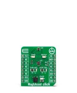
Mag&Accel Click is based on the NMH1000, a Hall-effect magnetic field switch, and the FXLS8974CF, a 3-axis low-g accelerometer, both from NXP Semiconductor. The switch processes its input over the functional blocks that consist of a configurable state machine, an analog-to-voltage conversion of the input, and a comparison to generate the bi-state output. The output is arranged in a linear succession. The NMH1000 has a transducer that generates a small charge proportional to the proximal magnetic flux density. The Hall-effect charge is converted to voltage and compared with the pre-defined threshold voltage. This determines the state of the switch’s output.
The FXLS8974CF accelerometer has a ±2/4/8/16 g user-selectable, full-scale measurement range with a 12-bit acceleration data output. It can work in several modes, such as active, hibernate, standby, and more. The integrated FIFO/LIFO buffer of 144 bytes can store 32 12-bit X/Y/Z/ data triplets. The sensor also has flexible data change detection, such as motion, freefall, and other inertial events.
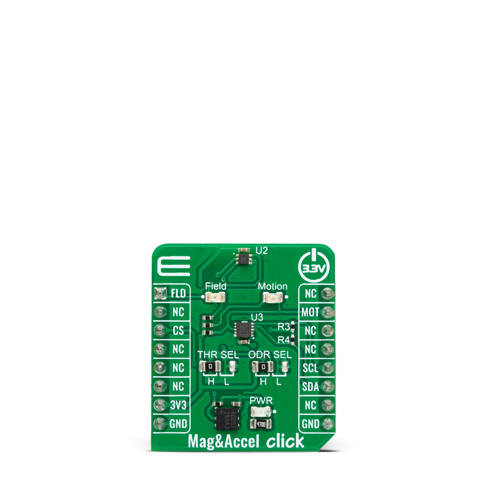
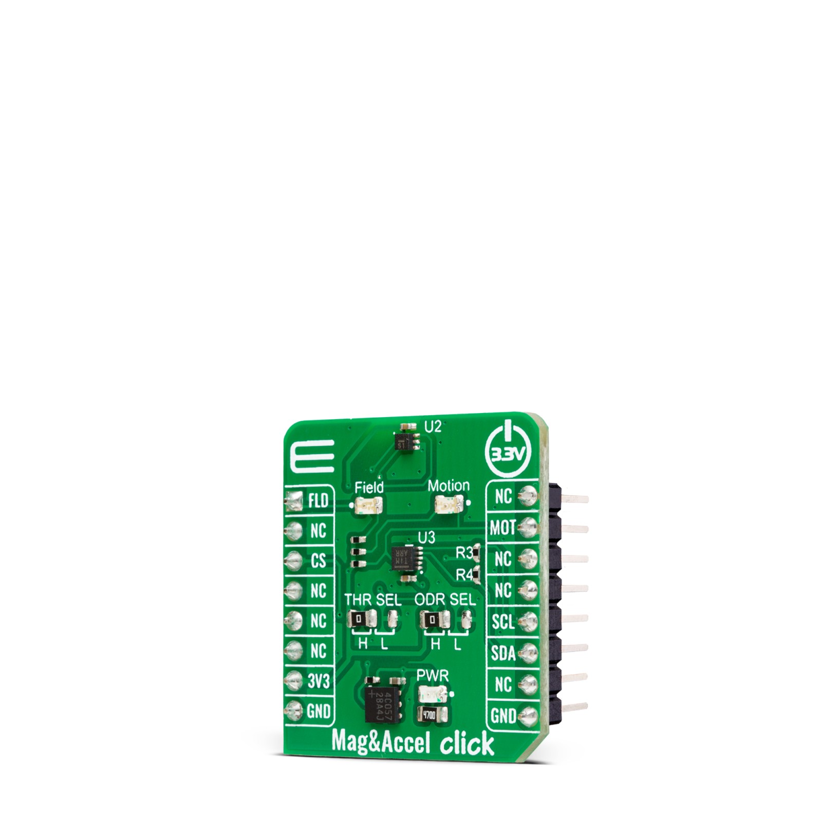
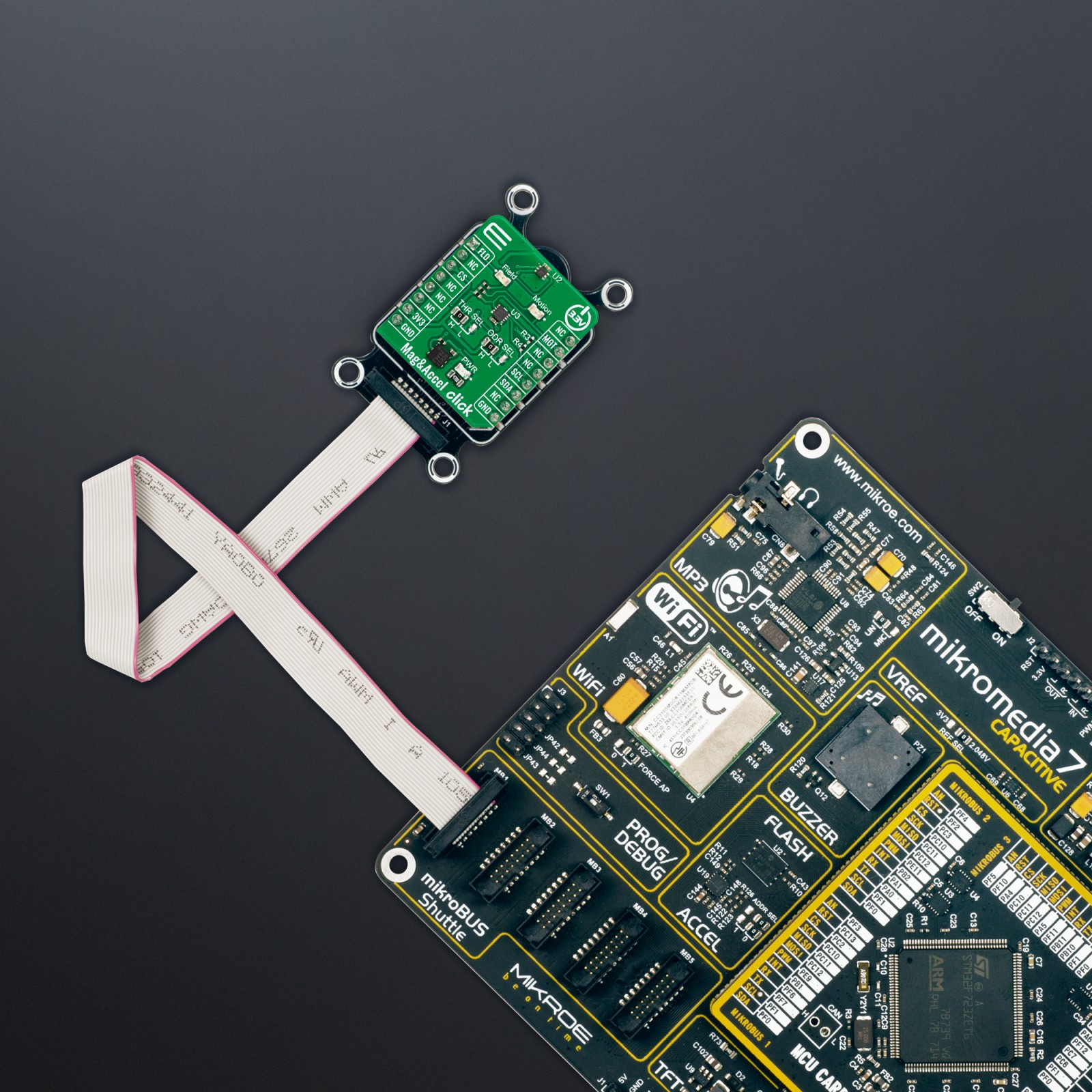
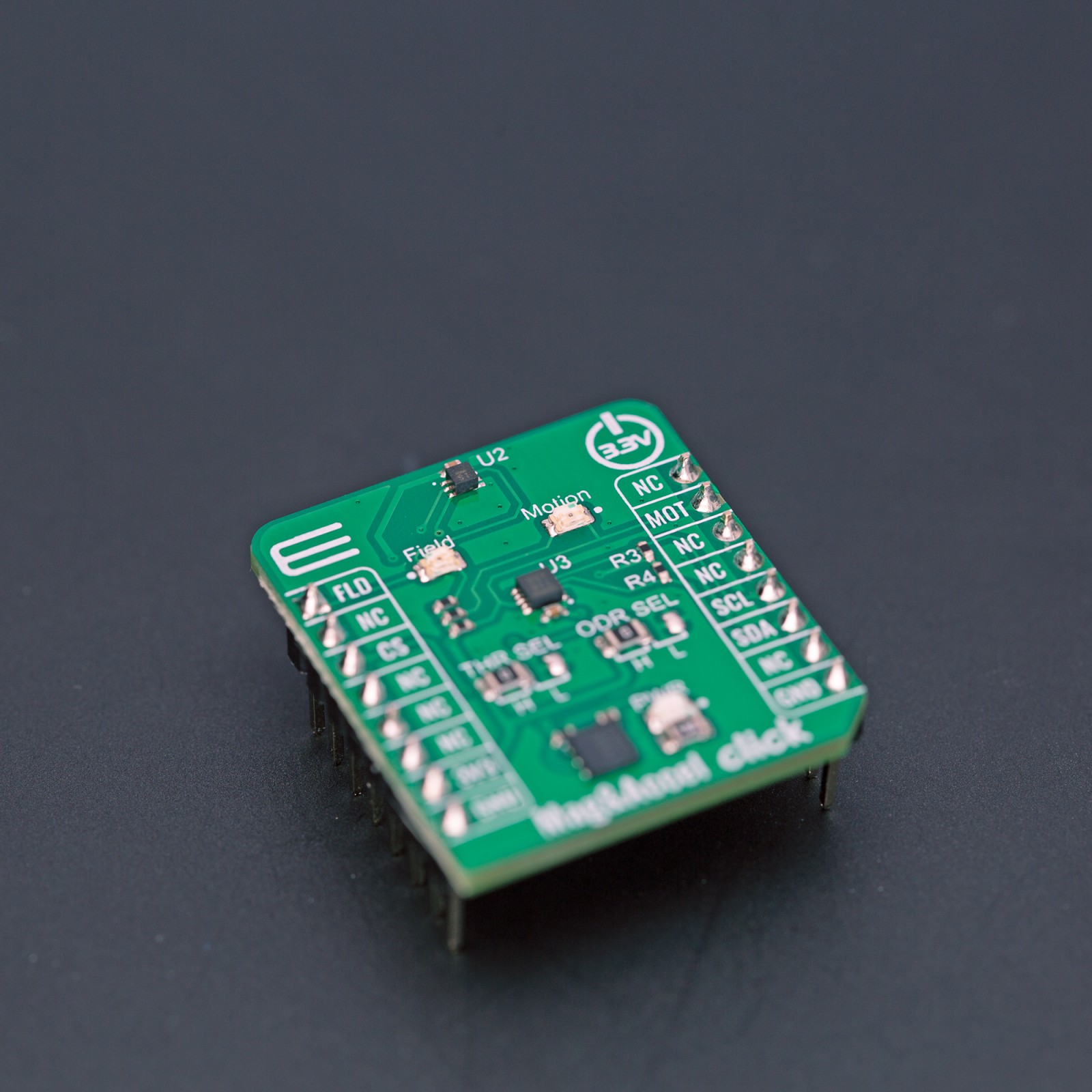
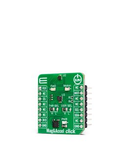
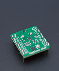
Mag&Accel Click uses a standard 2-wire I2C interface to allow the host MCU to communicate with the accelerometer. The FXLS8974CF uses a motion MOT pin to interrupt the host MCU if the motion is detected, with an accompanying Motion LED for a visual presentation. The NMH1000 is set in a standalone mode. The output of the magnetic switch, according to the pre-defined threshold, is available over the output OUT pin and, in addition, over the Field LED for visual presentation. The threshold itself can be set over the THR SEL jumper between high, medium, and low thresholds (±230, ±160, ±100G). You can also set the sampling rate over the ODR SEL jumper between high, medium, and low (10, 1, 0.1Hz).
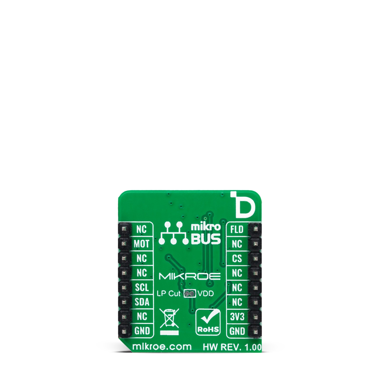
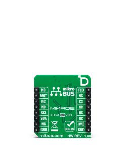
In addition, there is an LP Cut jumper at the bottom of the Mag&Accel Click board™, with which a low power consumption feature can be achieved.
This Click board™ can be operated only with a 3.3V logic voltage level. The board must perform appropriate logic voltage level conversion before using MCUs with different logic levels. Also, it comes equipped with a library containing functions and an example code that can be used as a reference for further development.
Specifications
Type
Acceleration,Magnetic,Motion
Applications
Can be used for the development of various industrial and home applications where the magnetic field detection and the acceleration of the object is an essence
On-board modules
NMH1000 – Hall-effect magnetic field switch from NXP Semiconductor
FXLS8974CF – 3-axis low-g accelerometer both from NXP Semiconductor
Key Features
Selectable threshold, selectable sample rate, output indicates of absence of a magnetic field as compared to an internally set threshold, consists of a state machine, analog-to-voltage conversion, generation of a bi-state output, arranged in linear succession, user-selectable, full-scale measurement ranges, high precision, FIFO buffers, flexible sensor data change detection function, and more
Interface
Analog,I2C
Feature
ClickID
Compatibility
mikroBUS™
Click board size
S (28.6 x 25.4 mm)
Input Voltage
3.3V
Pinout diagram
This table shows how the pinout on Mag&Accel Click corresponds to the pinout on the mikroBUS™ socket (the latter shown in the two middle columns).
Onboard settings and indicators
Label | Name | Default | Description |
---|---|---|---|
LD1 | PWR | – | Power LED Indicator |
LD2 | Motion | – | Motion Detection LED Indicator |
LD3 | Field | – | Magnetic Field LED Indicator |
JP1 | LP Cut | Connected | Low Power Selection |
– | THR SEL | Left | Threshold Selection H/L: Left position H, Right position L |
– | ODR SEL | Left | Sampling Rate Selection H/L: Left position H, Right position L |
Mag&Accel Click electrical specifications
Description | Min | Typ | Max | Unit |
---|---|---|---|---|
Supply Voltage | – | 3.3 | – | V |
Magnetic Field Threshold | ±100 | – | ±230 | G |
Sensitivity | – | 1.75 | – | G/LSB |
Acceleration Measurement Range | ±2 | – | ±16 | g |
Software Support
We provide a library for the MagAccel Click as well as a demo application (example), developed using MIKROE compilers. The demo can run on all the main MIKROE development boards.
Package can be downloaded/installed directly from NECTO Studio Package Manager (recommended), downloaded from our LibStock™ or found on Mikroe github account.
Library Description
This library contains API for MagAccel Click driver.
Key functions
-
magaccel_get_axes_data
This function reads the accelerometer sensor axes data. -
magaccel_set_op_mode
This function sets the desired operating mode of the sensor. -
magaccel_check_mag_field
This function checks the magnetic field y by reading the states of the FLD (AN) pin.
Example Description
This library contains API for the Mag&Accel Click driver. The library initializes and defines the I2C drivers to write and read data from registers, as well as the default configuration for reading accelerator data.
void application_task ( void )
{
if ( MAGACCEL_DATA_READY == magaccel_check_data_ready( &magaccel ) )
{
magaccel_axes_t acc_axis;
magaccel_get_axes_data( &magaccel, &acc_axis );
if ( MAGACCEL_DET_MAG_FIELD == magaccel_check_mag_field( &magaccel ) )
{
log_printf( &logger, " Presence of a magnetic fieldrn" );
log_printf( &logger, "_________________rn" );
}
log_printf( &logger, " Accel X: %.2f mgrn", acc_axis.x );
log_printf( &logger, " Accel Y: %.2f mgrn", acc_axis.y );
log_printf( &logger, " Accel Z: %.2f mgrn", acc_axis.z );
log_printf( &logger, "_________________rn" );
Delay_ms( 100 );
}
}
The full application code, and ready to use projects can be installed directly from NECTO Studio Package Manager (recommended), downloaded from our LibStock™ or found on Mikroe github account.
Other Mikroe Libraries used in the example:
- MikroSDK.Board
- MikroSDK.Log
- Click.MagAccel
Additional notes and informations
Depending on the development board you are using, you may need USB UART click, USB UART 2 Click or RS232 Click to connect to your PC, for development systems with no UART to USB interface available on the board. UART terminal is available in all MIKROE compilers.
mikroSDK
This Click board™ is supported with mikroSDK – MIKROE Software Development Kit. To ensure proper operation of mikroSDK compliant Click board™ demo applications, mikroSDK should be downloaded from the LibStock and installed for the compiler you are using.
For more information about mikroSDK, visit the official page.