-
×
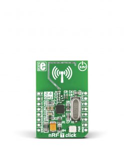 nRF T Click
1 × R205.00
nRF T Click
1 × R205.00
Subtotal: R205.00


R1,650.00 ex. VAT
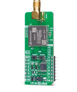
LTE IoT 10 Click is a compact add-on board that provides reliable LTE-M and NB-IoT connectivity for industrial and commercial IoT applications. This board features the Monarch 2 GM02S, a dual-mode LTE-M/NB-IoT module from Sequans (based on Sequans SQN3430 Chipset), offering global band support from 617MHz to 2.2GHz (covering bands 1,2,3,4,5,8,12,13,14,17,18,19,20,25,26,28,66,85). The GM02S module is 3GPP LTE Release 14 (upgradable to Release 17), embedded IP stack with multiple protocol support including PPP. It enables quick switching between LTE-M and NB-IoT modes for attaching to LTE live network or test equipment (CMW500 or similar). It includes UART interface for debugging and firmware upgrades. Additional features include a wake button, reset functionality, visual status indicators, an SMA connector for LTE antennas, and a micro SIM card slot. LTE IoT 10 Click is ideal for smart meters, industrial sensors, asset tracking, smart home and city applications, wearables, and healthcare monitoring solutions requiring power-efficient cellular IoT connectivity.
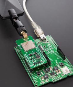
LTE IoT 10 Click is fully compatible with the mikroBUS™ socket and can be used on any host system supporting the mikroBUS™ standard. It comes with the mikroSDK open-source libraries, offering unparalleled flexibility for evaluation and customization. What sets this Click board™ apart is the groundbreaking ClickID feature, enabling your host system to seamlessly and automatically detect and identify this add-on board.
Stock: Lead-time applicable.
| 5+ | R1,567.50 |
| 10+ | R1,485.00 |
| 15+ | R1,402.50 |
| 20+ | R1,349.70 |
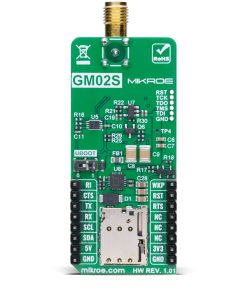
LTE IoT 10 Click is based on the Monarch 2 GM02S module from Sequans, designed to provide reliable LTE-M and NB-IoT connectivity. The GM02S is a highly optimized dual-mode LTE-M and NB-IoT solution featuring global band support from 617MHz to 2.2GHz (bands 1,2,3,4,5,8,12,13,14,17,18,19,20,25,26,28,66,85), making it compatible with both public and private LTE networks worldwide. The board can be used for attaching to LTE live network or test equipment (CMW500 or similar). Engineered with Sequans’ second-generation Monarch 2 chip platform (Sequans SQN3430 Chipset), this module ensures superior performance, significantly reduced power consumption (industry lowest deep sleep mode at 1μA and best-in-class eDRX and PSM), and robust security, making it an ideal solution for industrial and commercial IoT solutions requiring low power and high reliability, including smart meters, industrial sensors, asset tracking systems, smart home and city applications, wearable devices, and healthcare monitoring solutions.

The GM02S module leverages over 15 years of Sequans’ expertise in 4G+ connectivity and comes with a mature, carrier-approved LTE protocol stack, ensuring seamless network integration. Its Single-SKU™ RF front end allows operation across all global LTE bands, eliminating the need for regional variations and simplifying deployment. With a transmission power of +23dBm across all bands, the GM02S delivers strong and stable connectivity, even in challenging environments. Additionally, the module complies with 3GPP LTE Release 14, with the potential for future upgrades up to Release 17, ensuring long-term compatibility with evolving network standards.
One of the key advantages of the GM02S module is its ability to switch between LTE-M and NB-IoT modes (Cat M1, NB1, NB2) with a single firmware image, providing unmatched flexibility in various IoT implementations. It also incorporates an embedded IP stack, supporting TCP with TLS 1.3, UDP with DTLS 1.2, CoAP/MQTT, HTTP/FTP, and more, making it well-suited for secure data communication.
Communication between the GM02S and the host MCU is made through a UART interface, using standard UART RX and TX pins and hardware flow control pins (CTS/RTS/RI – Clear to Send/Ready to Send/Ring Indicator) for data transfer with a default communication speed of 115200bps. The board also features a FW upgrade switch on the back of the board labeled UBOOT to manage firmware upgrades. This switch has positions 0 for normal operation and 1 for firmware upgrade, ensuring a straightforward upgrade process. A dedicated UART interface is available through test points labeled as DBG for debugging and module upgrades. In addition, the board also features JTAG interface pins, an industry-standard solution for verifying designs and testing printed circuit boards.
The LTE IoT 10 Click includes several additional functionalities that enhance its usability and control. The WAKE button allows users to wake the module from Sleep mode, while the RESET button provides a quick way to reset the module. These functions can also be controlled digitally via the mikroBUS™ pins WKP and RST, offering greater flexibility. Moreover, these controls have dedicated test points for easier debugging and testing. The board also features some visual indicators to provide real-time status updates. The first red PMS LED signals the power-saving status, giving insight into the module’s low-power operation mode. The second yellow STAT LED indicates the module’s power status, ensuring real-time monitoring of its operational state.
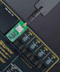
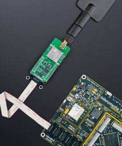
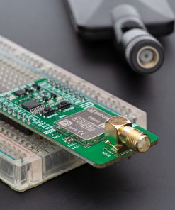
The board features one SMA connector for the main LTE antenna that MIKROE offers, like the LTE Flat Rotation Antenna or LTE Rubber Antenna, for flexible and efficient connectivity options. The board has a micro SIM card holder that supports 1.8V uSIM cards, ensuring compatibility with a wide range of cellular networks and allowing users to select the most appropriate service provider for their particular use case.
This Click board™ can operate with both 3.3V and 5V logic voltage levels selected via the VCC SEL jumper. Since the GM02S module communicates at 1.8V, logic-level translators, the TXB0106 and PCA9306, are also used for proper operation and an accurate signal-level translation. This way, both 3.3V and 5V capable MCUs can use the communication lines properly. Also, this Click board™ comes equipped with a library containing easy-to-use functions and an example code that can be used as a reference for further development.
Type
LTE IoT
Applications
Ideal for smart meters, industrial sensors, asset tracking, smart home and city applications, wearables, and healthcare monitoring solutions
On-board modules
GM02S – dual-mode LTE-M/NB-IoT module from Sequans
Key Features
LTE Cat M1, NB1, NB2 with global band support, 3GPP LTE Release 14 compliance (upgradable to Release 17), +23dBm TX power across all bands, UART interface, JTAG, supports PPP, TCP/TLS 1.3, UDP/DTLS 1.2, CoAP/MQTT, HTTP/FTP, firmware upgrade, SIM card support, and more
Interface
I2C,UART
Feature
ClickID
Compatibility
mikroBUS™
Click board size
L (57.15 x 25.4 mm)
Input Voltage
3.3V or 5V
This table shows how the pinout on LTE IoT 10 Click corresponds to the pinout on the mikroBUS™ socket (the latter shown in the two middle columns).
| Notes | Pin | Pin | Notes | ||||
|---|---|---|---|---|---|---|---|
| Module Wake-Up | WKP | 1 | AN | PWM | 16 | RI | Ring Indicator |
| Reset / ID SEL | RST | 2 | RST | INT | 15 | CTS | UART CTS |
| UART RTS / ID COMM | RTS | 3 | CS | RX | 14 | TX | UART TX |
| NC | 4 | SCK | TX | 13 | RX | UART RX | |
| NC | 5 | MISO | SCL | 12 | SCL | I2C Clock | |
| NC | 6 | MOSI | SDA | 11 | SDA | I2C Data | |
| Power Supply | 3.3V | 7 | 3.3V | 5V | 10 | 5V | Power Supply |
| Ground | GND | 8 | GND | GND | 9 | GND | Ground |
| Label | Name | Default | Description |
|---|---|---|---|
| LD1 | PWR | – | Power LED Indicator |
| LD2 | STAT | – | Module Status LED Indicator |
| LD3 | PMS | – | Power Saving Status LED Indicator |
| JP1 | VCC SEL | Left | Power Voltage Level Selection 3V3/5V: Left position 3V3, Right position 5V |
| T1 | WAKE | – | Module Wake Button |
| T2 | RESET | – | Module Reset Button |
| Description | Min | Typ | Max | Unit |
|---|---|---|---|---|
| Supply Voltage | 3.3 | – | 5 | V |
| Frequency Range | 617 | – | 2200 | MHz |
| Sensitivity | -105 | – | -108 | dBm |
| Output Power | – | +23 | – | dBm |
LTE IoT 10 Click demo application is developed using the NECTO Studio, ensuring compatibility with mikroSDK‘s open-source libraries and tools. Designed for plug-and-play implementation and testing, the demo is fully compatible with all development, starter, and mikromedia boards featuring a mikroBUS™ socket.
Example Description
Application example shows device capability of connecting to the network and sending SMS or TCP/UDP messages using standard “AT” commands.
Key Functions
lteiot10_cfg_setup This function initializes Click configuration structure to initial values.lteiot10_init This function initializes all necessary pins and peripherals used for this Click board.lteiot10_set_sim_apn This function sets APN for sim card.lteiot10_send_sms_text This function sends text message to a phone number.lteiot10_cmd_set This function sets a value to a specified command of the Click module.Application Init
Initializes the driver and logger.
Application Task
Application task is split in few stages:
Powers up the device, performs a device factory reset and reads system information.
Sets configuration to device to be able to connect to the network.
Waits for the network registration indicated via CEREG command and then checks the signal quality report.
Configures device for the selected example.
Depending on the selected demo example, it sends an SMS message (in PDU or TXT mode) or TCP/UDP message. By default, the TCP/UDP example is selected.
Application Output
This Click board can be interfaced and monitored in two ways:
Additional Notes and Information
The complete application code and a ready-to-use project are available through the NECTO Studio Package Manager for direct installation in the NECTO Studio. The application code can also be found on the MIKROE GitHub account.
| Weight | 27 g |
|---|---|
| Brand | MikroElektronika |