How does it work?
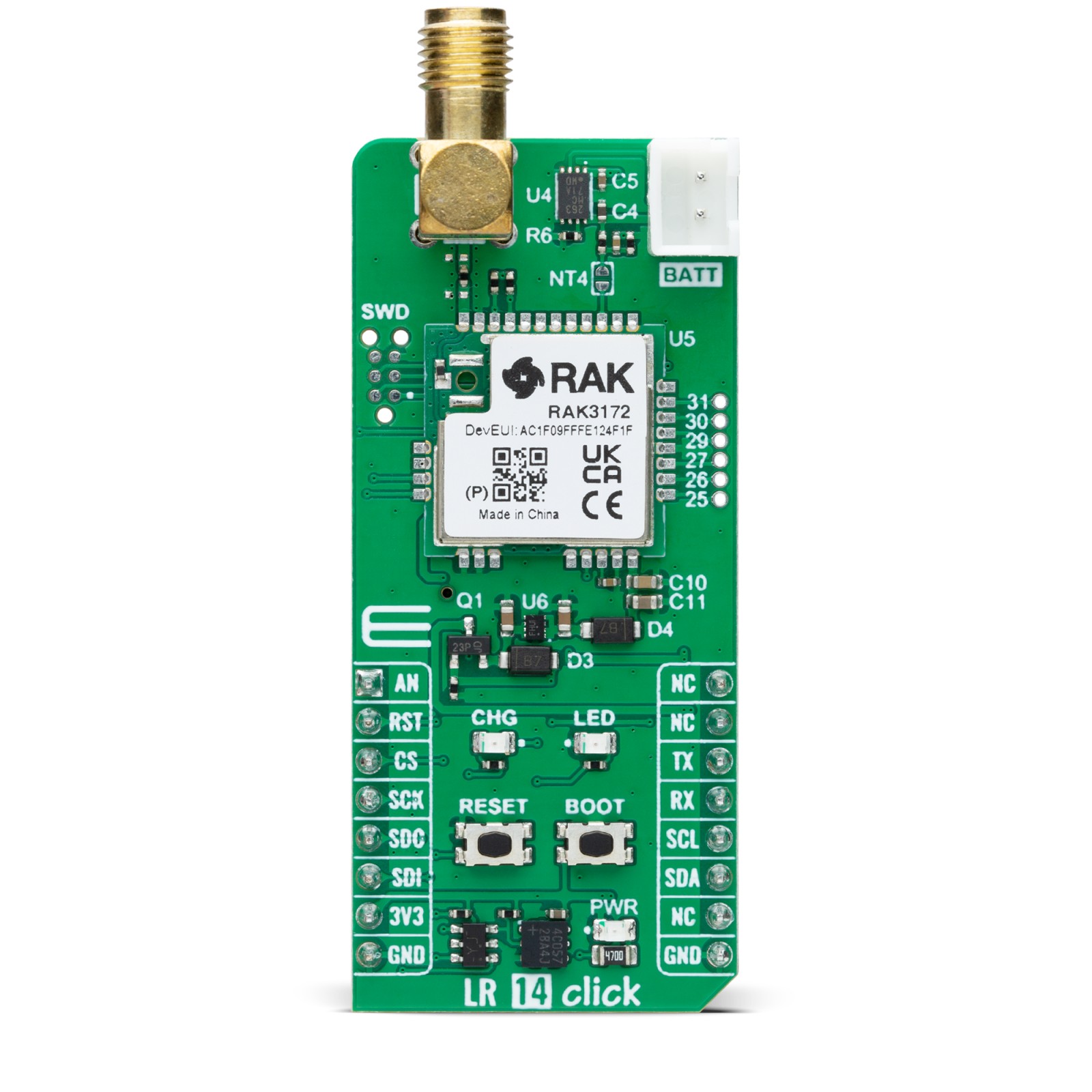
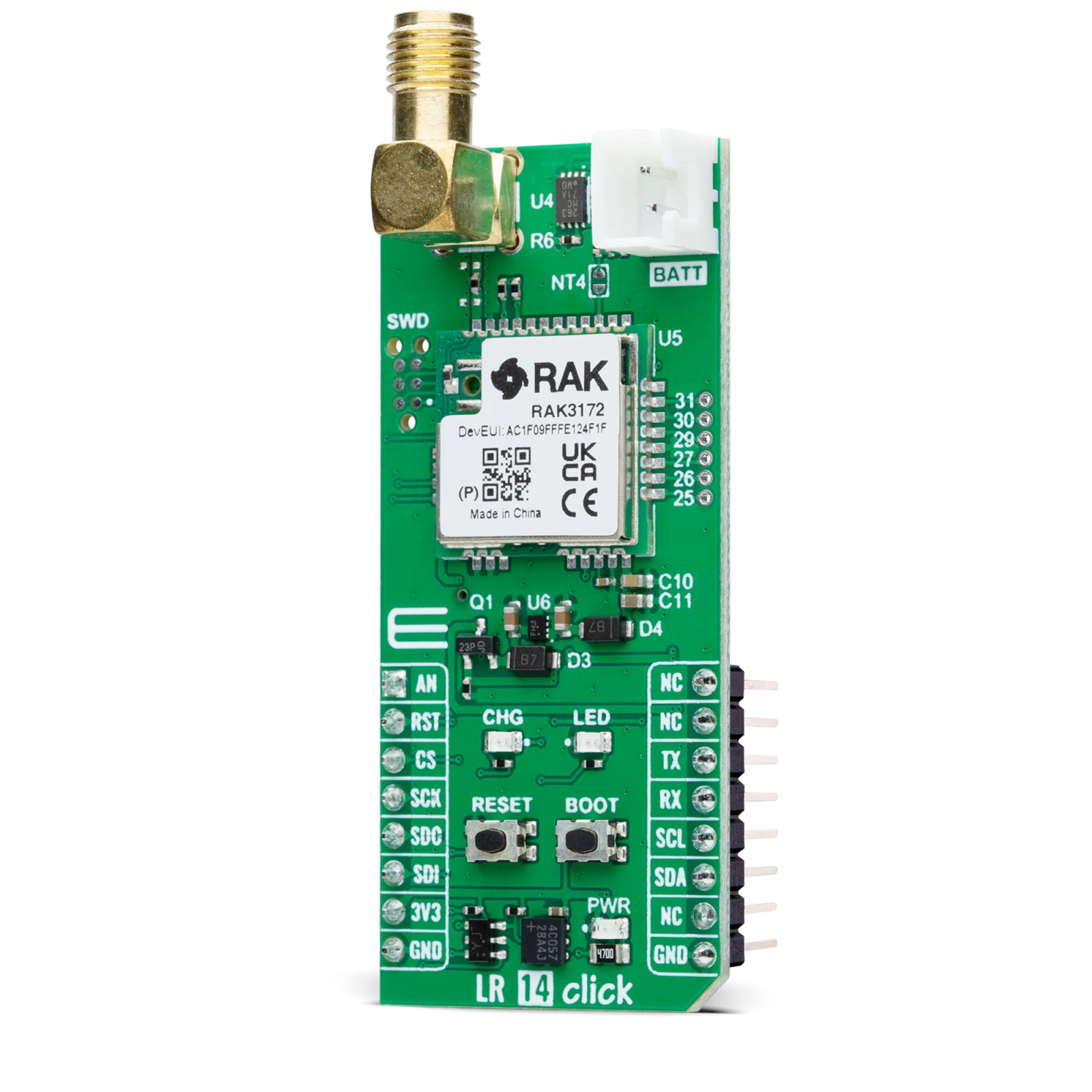
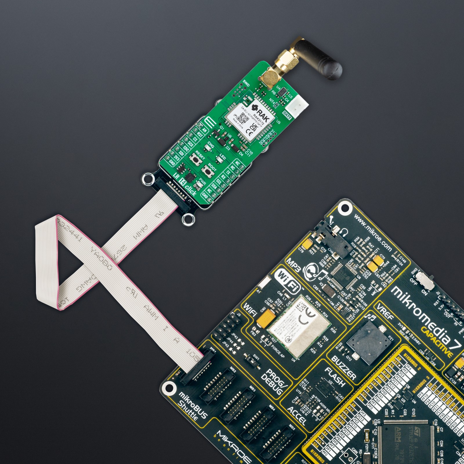
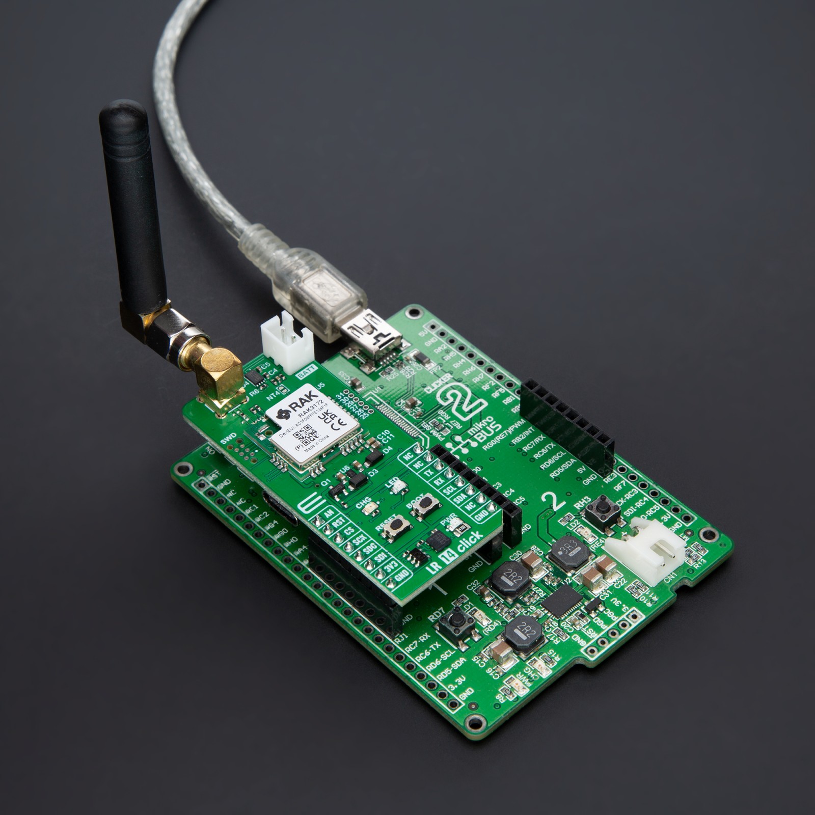
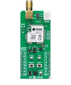
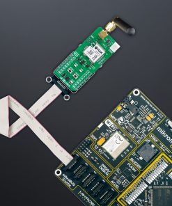
LR 14 Click is based on the RAK3172, Class A/B/C LoRaWAN 1.0.3 low-power module from RAKwireless Technology. This module incorporates the STM32WLE5CC, an ARM Cortex-M4 32-bit chip, and is designed for low-power, long-range data transmission in wireless applications, ideal for IoT networks. The RAK3172 module in LR 14 Click allows easy integration with LoRaWAN server platforms such as TheThingsNetwork (TTN), Chirpstack, and Actility, facilitating a broad range of LoRaWAN applications. It also supports LoRa Point-to-Point (P2P) communication, enabling users to set up custom LoRa networks quickly and effectively without relying on external servers. Compatible with multiple frequency bands — including IN865, EU868, and RU864 — the RAK3172 module provides significant flexibility, achieving communication distances of over 15km when paired with an optimized antenna.
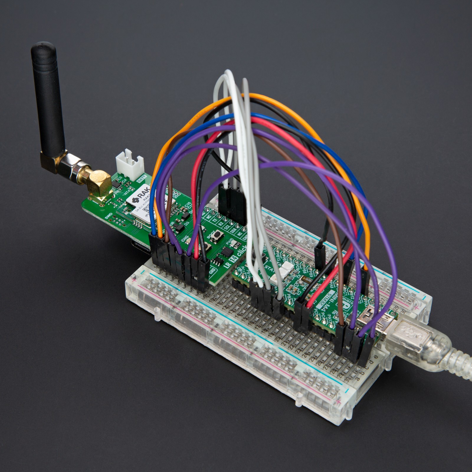
Operating the module is straightforward, as the RAK3172 can be configured using AT commands sent through a UART interface, providing an intuitive control scheme for fine-tuning modes and operational parameters. This versatility and its low-power capabilities make LR 14 Click particularly suited to battery-powered applications, where efficient energy consumption is essential. Additionally, LR 14 Click includes both SPI and I2C interfaces to expand its functionality. The SPI interface is dedicated to interacting with the RF subsystem of the STM32WLE5CCU6, enabling robust management of the module’s wireless communication capabilities. Meanwhile, the I2C interface allows the board to function as a host, leveraging its internal MCU to control external I2C peripheral devices.
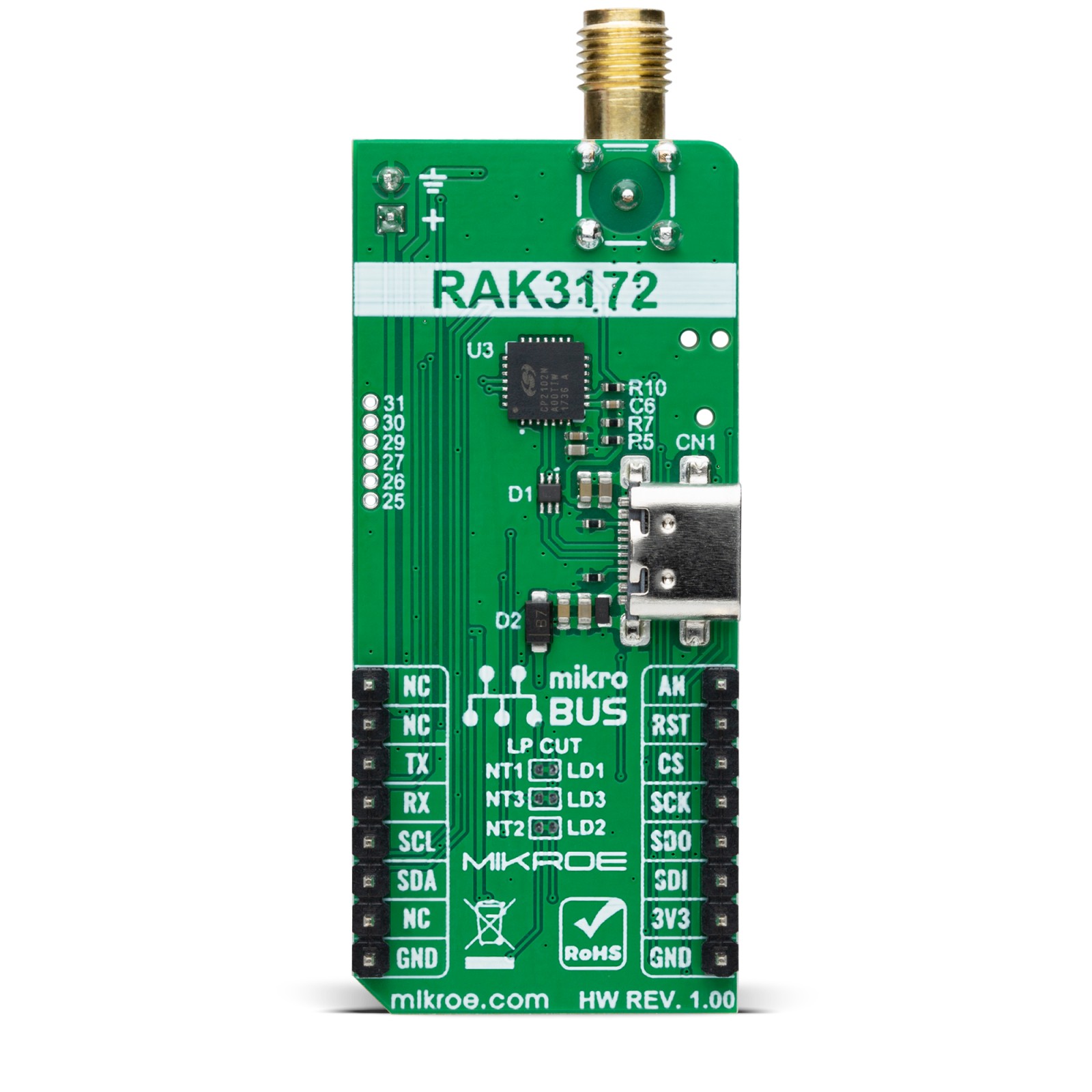
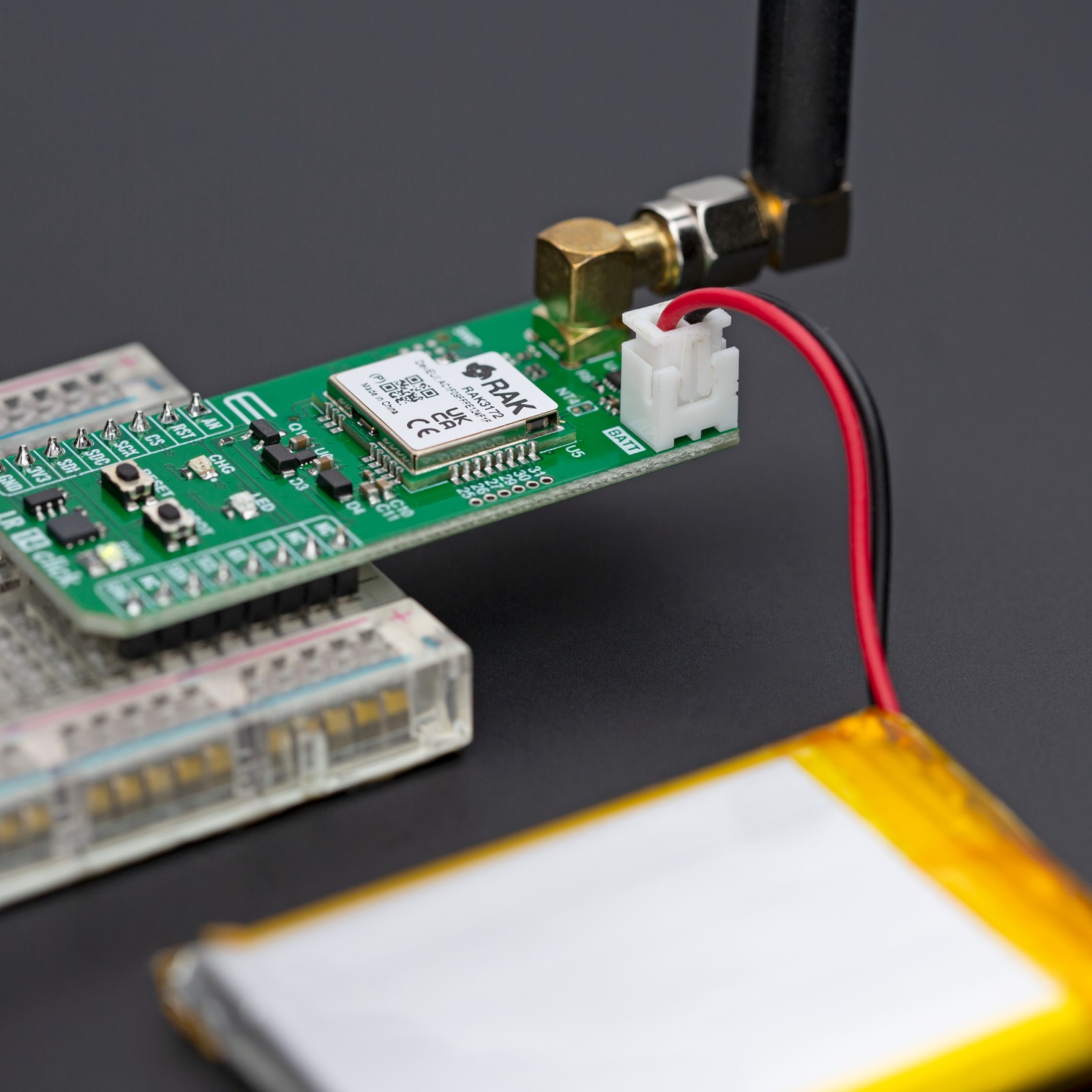
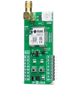
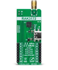
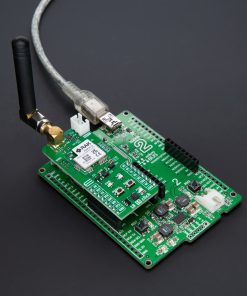
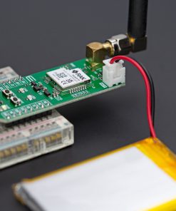
The Click board™ also includes a USB Type-C connector, allowing both power supply and configuration via a PC. This functionality is enabled by the CP2102N, a highly integrated USB-to-UART bridge, along with the NCP186 LDO regulator, which converts the USB supply to the necessary 3.3V for the module. Additionally, the board can operate as a fully standalone unit with a battery connected through its dedicated battery connector. This battery is rechargeable by the MC34671 battery charger. The orange CHG LED visually indicates the charging process, providing real-time status feedback. In addition to the interface pins, this board includes extra mikroBUS™ pins for enhanced control. The RST pin and a dedicated RST button allow for easy module resetting, while the AN pin enables monitoring of the connected battery’s status.
LR 14 Click incorporates several additional features that enhance its functionality and adaptability. A 6-pin SWD connector enables firmware updates for the RAK3172 module, ensuring users can easily keep the module up to date. The BOOT button provides control over the bootloader; pressing it initiates the bootloader for firmware updates via UART, and releasing it exits the bootloader, returning control to the main application firmware. For power optimization, specific traces on the back of the board can be cut to disable components like LED indicators and battery voltage monitoring, reducing power consumption. The board also includes an unsoldered header with six GPIO pins, allowing for further customization. Additionally, a user-configurable red LED indicator and an SMA antenna connector for connecting a Rubber 868MHz Antenna for optimal performance, available through the MIKROE shop.
This Click board™ can be operated only with a 3.3V logic voltage level. The board must perform appropriate logic voltage level conversion before using MCUs with different logic levels. Also, it comes equipped with a library containing functions and an example code that can be used as a reference for further development.
Specifications
Type
LoRa,Sub-1 GHz Transceievers
Applications
Ideal for long-distance, low-power communication applications, such as remote sensing, asset tracking, and IoT deployments
On-board modules
RAK3172 – Class A/B/C LoRaWAN 1.0.3 low-power module from RAKwireless Technology
Key Features
Supports LoRaWAN and LoRa Point-to-Point (P2P) modes, compatible with IN865, EU868, and RU864, multiple interfaces, battery support, standalone operation, reset and boot management, firmware update, and more
Interface
Analog,I2C,SPI,UART,USB
Feature
ClickID
Compatibility
mikroBUS™
Click board size
L (57.15 x 25.4 mm)
Input Voltage
3.3V,External
Pinout diagram
This table shows how the pinout on LR 14 Click corresponds to the pinout on the mikroBUS™ socket (the latter shown in the two middle columns).
Onboard settings and indicators
Label | Name | Default | Description |
---|---|---|---|
LD1 | CHG | – | Battery Charging LED Indicator |
LD2 | PWR | – | Power LED Indicator |
LD3 | LED | – | User-Configurable LED Indicator |
T1 | RESET | – | Reset Button |
T2 | BOOT | – | Boot Button |
LR 14 Click electrical specifications
Description | Min | Typ | Max | Unit |
---|---|---|---|---|
Supply Voltage | – | 3.3 | – | V |
Frequency Range | – | 868 | – | MHz |
Range | – | – | 15 | km |
RX Sensitivity | – | -148 | – | dBm |
TX Power | – | – | +22 | dBm |
Software Support
We provide a library for the LR 14 Click as well as a demo application (example), developed using MIKROE compilers. The demo can run on all the main MIKROE development boards.
Package can be downloaded/installed directly from NECTO Studio Package Manager (recommended), downloaded from our LibStock™ or found on MIKROE github account.
Library Description
This library contains API for LR 14 Click driver.
Key functions
-
lr14_cmd_run
This function sends a specified command to the click module. -
lr14_cmd_set
This function sets a value to a specified command of the click module. -
lr14_cmd_get
This function is used to get the value of a given command from the click module.
Example Description
This example demonstrates the use of LR 14 Click by showing the communication between two click boards configured in P2P network mode.
void application_task ( void )
{
switch ( app_state )
{
case LR14_POWER_UP:
{
if ( LR14_OK == lr14_power_up( &lr14 ) )
{
app_state = LR14_CONFIG_EXAMPLE;
log_printf( &logger, ">>> APP STATE - CONFIG EXAMPLE <<<rnn" );
}
break;
}
case LR14_CONFIG_EXAMPLE:
{
if ( LR14_OK == lr14_config_example( &lr14 ) )
{
app_state = LR14_EXAMPLE;
log_printf( &logger, ">>> APP STATE - EXAMPLE <<<rnn" );
}
break;
}
case LR14_EXAMPLE:
{
lr14_example( &lr14 );
break;
}
default:
{
log_error( &logger, " APP STATE." );
break;
}
}
}
The full application code, and ready to use projects can be installed directly from NECTO Studio Package Manager (recommended), downloaded from our LibStock™ or found on MIKROE github account.
Other MIKROE Libraries used in the example:
- MikroSDK.Board
- MikroSDK.Log
- Click.LR14
Additional notes and informations
Depending on the development board you are using, you may need USB UART click, USB UART 2 Click or RS232 Click to connect to your PC, for development systems with no UART to USB interface available on the board. UART terminal is available in all MIKROE compilers.
mikroSDK
This Click board™ is supported with mikroSDK – MIKROE Software Development Kit. To ensure proper operation of mikroSDK compliant Click board™ demo applications, mikroSDK should be downloaded from the LibStock and installed for the compiler you are using.
For more information about mikroSDK, visit the official page.