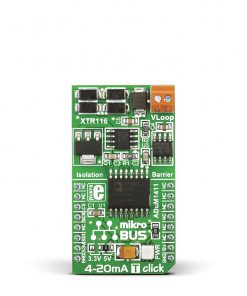
LPS22HB Click
R315.00 ex. VAT
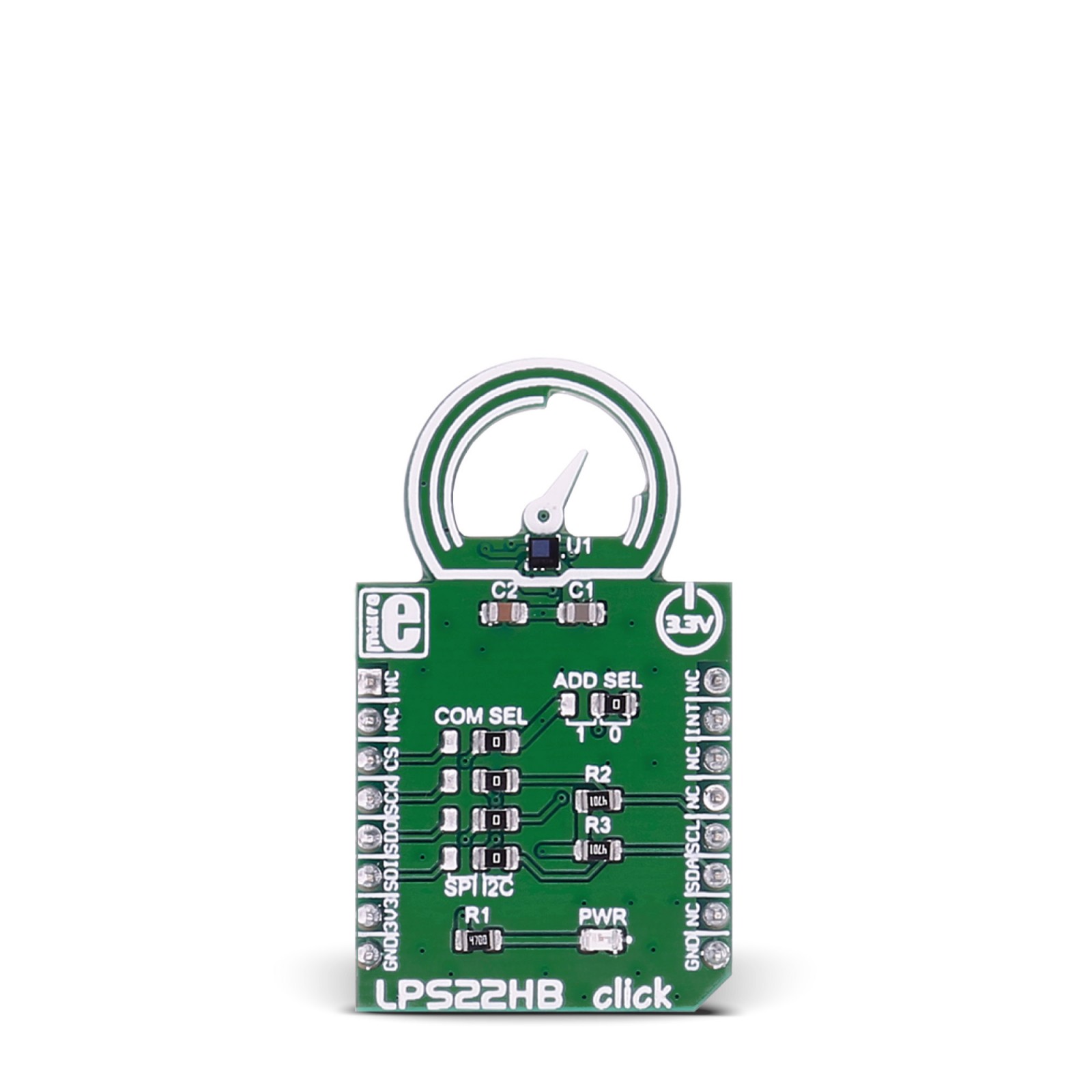
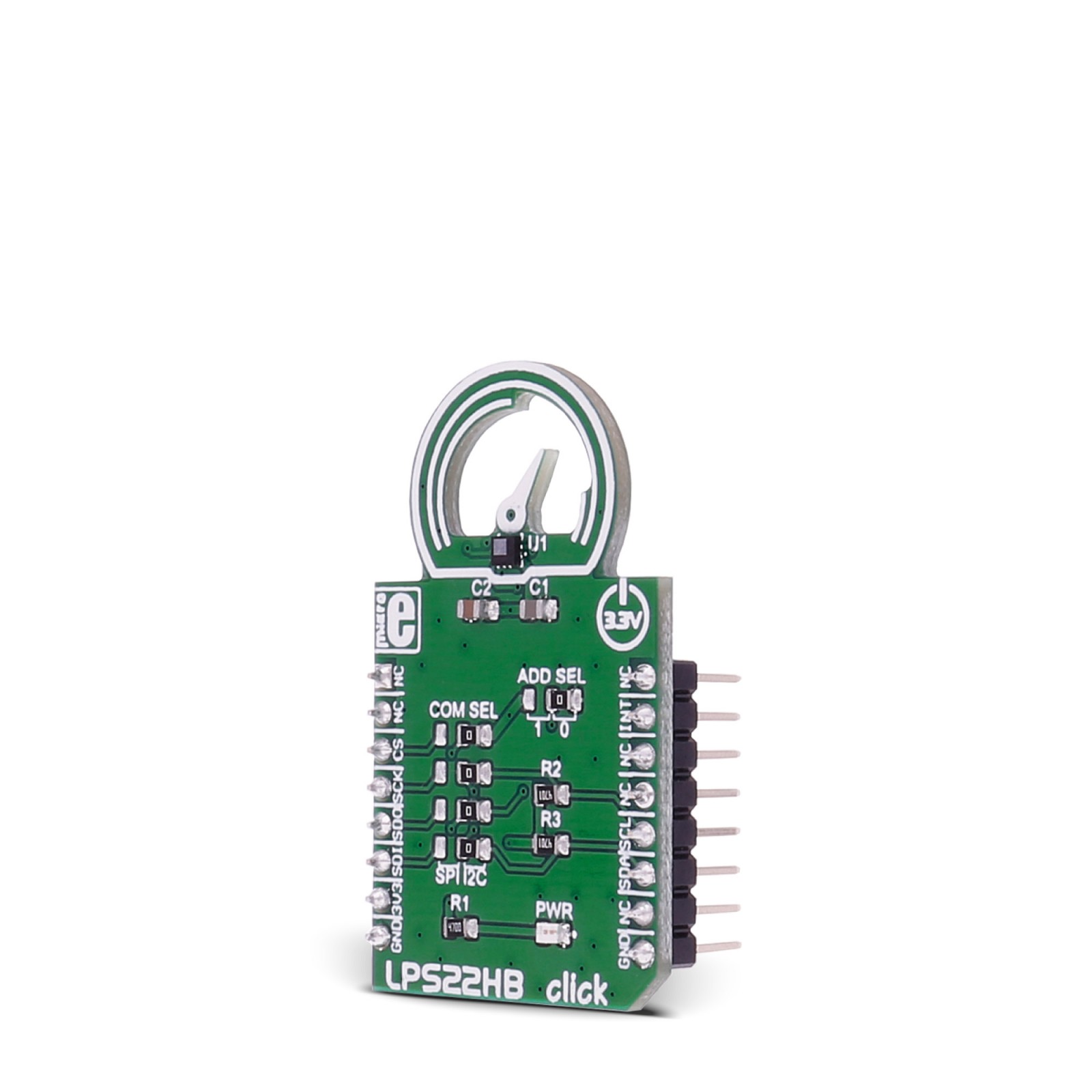
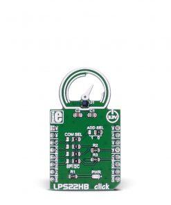
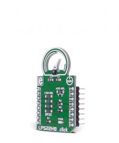
LPS22HB click is an easy solution for adding a digital barometer to your design. It carries the LPS22HB MEMS nano pressure sensor.
The click is designed to run on a 3.3V power supply. LPS22HB click communicates with the target microcontroller over I2C or SPI interface.
Stock: Lead-time applicable.
| 5+ | R299.25 |
| 10+ | R283.50 |
| 15+ | R267.75 |
| 20+ | R257.67 |
LPS22HB click is an easy solution for adding a digital barometer to your design. It carries the LPS22HB MEMS nano pressure sensor. The click is designed to run on a 3.3V power supply. LPS22HB click communicates with the target microcontroller over I2C or SPI interface.
How the click works
LPS22HB click carries the pressure sensor that measures 260-1260 hPa absolute pressure. Pressure values are then read out from the IC’s registers, through I2C or SPI communication.
LPS22HB sensor features
The LPS22HB is an ultra-compact piezoresistive absolute pressure sensor which functions as a digital output barometer.
The sensing element, which detects absolute pressure, consists of a suspended membrane. When pressure is applied, the membrane deflection induces an imbalance in the Wheatstone bridge piezoresistances, whose output signal is converted by the IC interface.
The sensor has a 24-bit pressure data output and a 16-bit temperature data output.
Specifications
Type
Pressure
Applications
Barometers for portable devices, GPS applications, Weather station equipment, etc.
On-board modules
LPS22HB pressure sensor
Key Features
260 to 1260 hPa absolute pressure range
Interface
GPIO,I2C,SPI
Feature
No ClickID
Compatibility
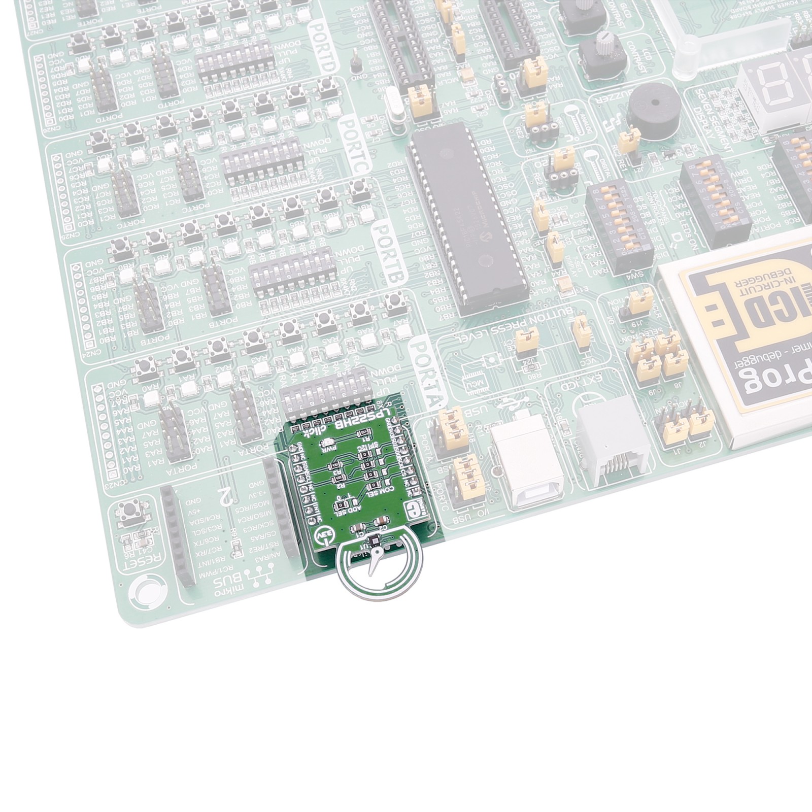
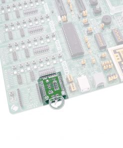
mikroBUS™
Click board size
M (42.9 x 25.4 mm)
Input Voltage
3.3V
Pinout diagram
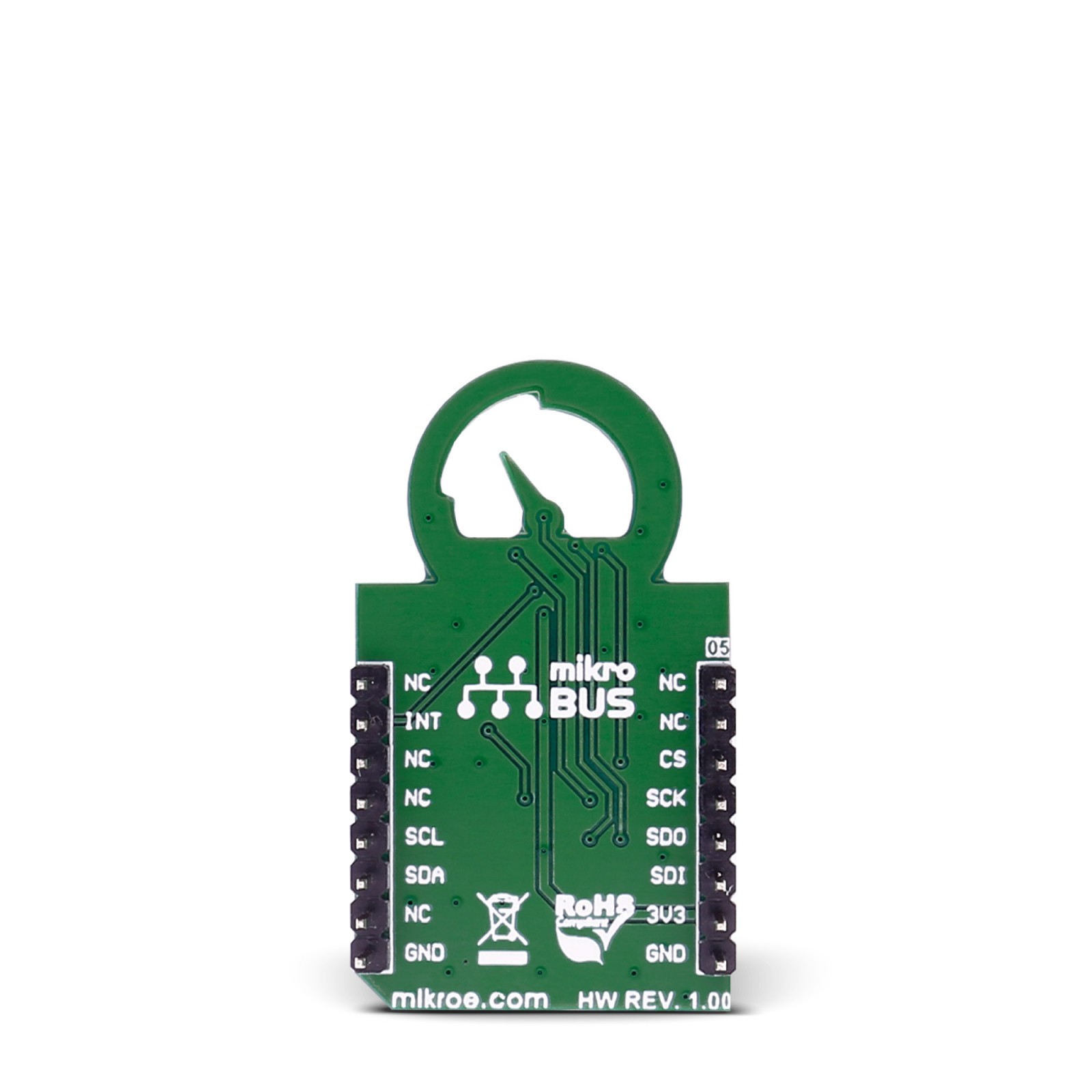
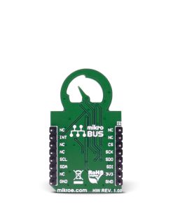
This table shows how the pinout on LPS22HB click corresponds to the pinout on the mikroBUS™ socket (the latter shown in the two middle columns).
Maximum ratings
| Description | Min | Typ | Max | Unit |
|---|---|---|---|---|
| Supply VOltage (Vdd) | 1.7 | 3.6 | V | |
| IO supply voltage(Vdd_IO) | 1.7 | Vdd+0.1 | V | |
| Overpressure | 2 | MPa | ||
| Operating pressure range | 260 | 1260 | hPa | |
| Pressure sensitivity | 4096 | LSB/hPa |
Jumpers and settings
| Designator | Name | Default Position | Default Option | Description |
|---|---|---|---|---|
| JP1 | COM SEL | Right | SCL(I2C) | Clock communication line Selection SCK/SCL, left position SCK, right position SCL |
| JP2 | COM SEL | Right | SDA(I2C) | Data communication line Selection SDI/SDA, left position SDI, right position SDA |
| JP3 | COM SEL | Right | ADD(I2C) | Communication Interface lines Selection SDO/ADD, left position SDO, right position ADD |
| JP4 | ADD SEL | Right | 0 | Less significant bit of the I2C slave address selection 1/0, left position 1, right position 0. |
| JP5 | COM SEL | Right | I2C | Communication interface selection CS/I2C, left position CS, right position I2C |
LEDs and buttons
| Designator | Name | Type | Description |
|---|---|---|---|
| PWR | PWR | LED | Power LED, lights green when Board is powered. |
Programming
Code examples for MCP1664 click, written for MikroElektronika hardware and compilers are available on Libstock.
Code snippet
The following code snippet shows the main function of the example, which first calls the initialization functions, and then reads and outputs temperature and pressure values every 5 seconds
01 void main()
02 {
03     char uartTxt [20];
04     systemInit();
05     LPS22HB_initDriver (0x5C, I2C1_Start, I2C1_Write, I2C1_Read );
06     Uart1_Write_Text ("rnInitialized");
07
08    while( 1 )
09     {
10          Uart1_Write_Text ("rnTemperature: ");
11          FloatToStr ( LPS22HB_readTemperature (), uartTxt);
12          uartTxt [5] = '';
13          Uart1_Write_Text (uartTxt);
14
15         Uart1_Write_Text ("    Pressure: ");
16          FloatToStr ( LPS22HB_readPressure (), uartTxt);
17          uartTxt [8] = '';
18          Uart1_Write_Text (uartTxt);
19
20          Delay_ms (5000);
21     }
22 }
Resources
Downloads
| Weight | 18 g |
|---|---|
| Brand | MikroElektronika |

