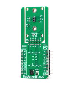
LightRanger 13 Click
R345.00 ex. VAT
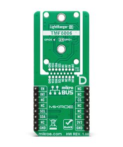
LightRanger 13 Click is a compact add-on board for precise distance measurement in various applications. This board features the TMF8806-1A, a time-of-flight (TOF) sensor from ams OSRAM, housed in an industry-leading small modular package. The sensor features advanced dTOF technology with high-sensitivity SPAD detection, a fast time-to-digital converter, and on-chip histogram processing, enabling accurate measurements within the 1cm to 500cm range at 30Hz. It supports calibration, dirt and smudge removal, and crosstalk compensation and operates reliably in both low-light and sunlight conditions. The board includes an I2C interface, an EN pin for power control, an INT pin for signaling measurement availability, and a Snap feature for flexible implementation. LightRanger 13 Click is ideal for robotics, home and building automation, projection and display systems, factory automation, access control, security systems, and smart appliances.
LightRanger 13 Click is fully compatible with the mikroBUS™ socket and can be used on any host system supporting the mikroBUS™ standard. It comes with the mikroSDK open-source libraries, offering unparalleled flexibility for evaluation and customization. What sets this Click board™ apart is the groundbreaking ClickID feature, enabling your host system to seamlessly and automatically detect and identify this add-on board, alongside a Click Snap feature introducing a new level of flexibility and ease of use.
Stock: Lead-time applicable.
| 5+ | R327.75 |
| 10+ | R310.50 |
| 15+ | R293.25 |
| 20+ | R282.21 |
How does it work?
LightRanger 13 Click is based on the TMF8806-1A, a time-of-flight (TOF) sensor from ams OSRAM designed for precise distance measurement in various applications. This sensor is housed in one of the smallest modular packages in the industry and incorporates a 940nm VCSEL that complies with Class 1 eye safety standards. Using single-photon avalanche diode (SPAD) technology, a fast time-to-digital converter (TDC) architecture, and on-chip histogram processing, the TMF8806-1A ensures highly accurate distance measurements across a detection range of 1cm to 500cm, even in challenging environments. This Click board™ is ideal for industrial, commercial, and residential use cases requiring high-resolution distance sensing, such as robotics, home and building automation, projection and display systems, factory automation, access control, security systems, and smart appliances.

The sensor’s dTOF technology, combined with its high-sensitivity SPAD detection, delivers exceptional signal-to-noise ratios and a wide dynamic range, ensuring reliable performance in both low-light and bright sunlight conditions. Its fast sub-nanosecond light pulse capability and 30Hz sensing rate enable rapid and precise distance detection, making it suitable for dynamic applications. The TMF8806-1A features built-in mechanisms for calibration, dirt and smudge removal, and crosstalk compensation, ensuring consistent accuracy over time. Additionally, its integrated eye-safety circuitry halts the VCSEL driver in case of a fault, enhancing operational safety.
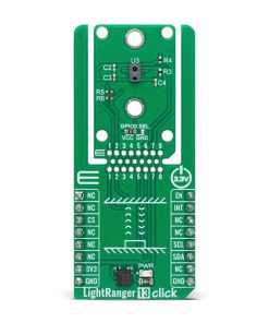
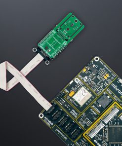
This Click board™ is designed in a unique format supporting the newly introduced MIKROE feature called “Click Snap.” Unlike the standardized version of Click boards, this feature allows the main IC area to become movable by breaking the PCB, opening up many new possibilities for implementation. Thanks to the Snap feature, the TMF8806-1A can operate autonomously by accessing its signals directly on the pins marked 1-8. Additionally, the Snap part includes a specified and fixed screw hole position, enabling users to secure the Snap board in their desired location.
LightRanger 13 Click communicates with the host MCU through an I2C interface, supporting a maximum clock frequency of 1MHz for fast data exchange. In addition to the standard interface pins, the board also features an EN pin, which acts as the device enable pin. Setting this pin to a HIGH logic level powers up the device, while setting it to LOW forces the sensor into a Shutdown mode, during which all memory content is erased. The board also includes an INT pin, configured as an open-drain interrupt output, which signals the host MCU when a ranging measurement is available, ensuring timely data processing.
Additionally, the Snap section of the board includes a GPIO0 SEL jumper, which allows for the selection of the TMF8806-1A’s I/O supply voltage. Setting the jumper to the VCC position enables a 3.3V or lower supply, such as 1.8V, while setting it to the GND position provides an even lower I/O supply voltage of 1.2V. After startup, the GPIO0 pin can function as a general-purpose GPIO output signal, accessible through the GPIO1 test point on the back of the board.
This Click board™ can be operated only with a 3.3V logic voltage level. The board must perform appropriate logic voltage level conversion before using MCUs with different logic levels. It also comes equipped with a library containing functions and example code that can be used as a reference for further development.
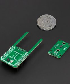
Click Snap
Click Snap is an innovative feature of our standardized Click add-on boards, introducing a new level of flexibility and ease of use. This feature allows for easy detachment of the main sensor area by simply snapping the PCB along designated lines, enabling various implementation possibilities. For detailed information about Click Snap, please visit the official page dedicated to this feature.
Specifications
Type
Optical
Applications
Ideal for robotics, home and building automation, projection and display systems, factory automation, access control, security systems, and smart appliances
On-board modules
TMF8806-1A – time-of-flight (TOF) sensor from ams OSRAM
Key Features
Distance measurement range up to 500cm, dTOF with SPAD detection, TDC architecture, and on-chip histogram processing, ±5% accuracy in various lighting conditions, including low-light and sunlight, I2C interface, integrated Class 1 VCSEL safety circuitry, Click Snap, and more
Interface
I2C
Feature
Click Snap,ClickID
Compatibility
mikroBUS™
Click board size
L (57.15 x 25.4 mm)
Input Voltage
3.3V
Pinout diagram
This table shows how the pinout on LightRanger 13 Click corresponds to the pinout on the mikroBUS™ socket (the latter shown in the two middle columns).
| Notes | Pin | Pin | Notes | ||||
|---|---|---|---|---|---|---|---|
| NC | 1 | AN | PWM | 16 | EN | Device Enable | |
| NC | 2 | RST | INT | 15 | INT | Interrupt | |
| ID COMM | CS | 3 | CS | RX | 14 | NC | |
| NC | 4 | SCK | TX | 13 | NC | ||
| NC | 5 | MISO | SCL | 12 | SCL | I2C Clock | |
| NC | 6 | MOSI | SDA | 11 | SDA | I2C Data | |
| Power Supply | 3.3V | 7 | 3.3V | 5V | 10 | NC | |
| Ground | GND | 8 | GND | GND | 9 | GND | Ground |
Onboard settings and indicators
| Label | Name | Default | Description |
|---|---|---|---|
| LD1 | PWR | – | Power LED Indicator |
| JP1 | GPIO0 SEL | Left | TMF8806-1A I/O Voltage Selection VCC/GND: Left position VCC, Right position GND |
LightRanger 13 Click electrical specifications
| Description | Min | Typ | Max | Unit |
|---|---|---|---|---|
| Supply Voltage | – | 3.3 | – | V |
| Wavelength | – | – | 940 | nm |
| Detection Distance | 1 | – | 500 | cm |
| Field of View (FoV) | – | 30 | – | deg |
Software Support
LightRanger 13 Click demo application is developed using the NECTO Studio, ensuring compatibility with mikroSDK‘s open-source libraries and tools. Designed for plug-and-play implementation and testing, the demo is fully compatible with all development, starter, and mikromedia boards featuring a mikroBUS™ socket.
Example Description
This application demonstrates the usage of the LightRanger 13 Click for distance measurement and monitoring.
Key Functions
lightranger13_cfg_setupConfig Object Initialization function.lightranger13_initInitialization function.lightranger13_default_cfgClick Default Configuration function.lightranger13_set_thresholdThis function sets a threshold level and interrupt persistance.lightranger13_start_measurementThis function starts a measurement (the configuration, factory calibration and state data are used from context object).lightranger13_read_resultThis function reads the measurement results.
Application Init
Initializes the logger and LightRanger 13 Click with default configuration, displays device information, performs factory calibration (if enabled), and sets up distance measurement thresholds (1mm-1000mm) with persistence (5 consecutive times) to ensure reliable readings. It then starts the measurement process.
Application Task
Waits for the data ready interrupt signal, indicating a new measurement is available. Upon receiving the signal, it reads the distance and temperature data from the sensor and logs the values to USB UART.
Application Output
This Click board can be interfaced and monitored in two ways:
- Application Output – Use the “Application Output” window in Debug mode for real-time data monitoring. Set it up properly by following this tutorial.
- UART Terminal – Monitor data via the UART Terminal using a USB to UART converter. For detailed instructions, check out this tutorial.
Additional Notes and Information
The complete application code and a ready-to-use project are available through the NECTO Studio Package Manager for direct installation in the NECTO Studio. The application code can also be found on the MIKROE GitHub account.
Resources
Downloads
| Weight | 18 g |
|---|---|
| Brand | MikroElektronika |