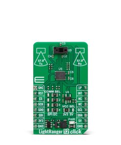
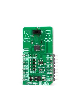
LightRanger 12 Click
R650.00 ex. VAT
LightRanger 12 Click is a compact add-on board for precise distance measurement and spatial mapping applications. This board features the VL53L8CH, an 8×8 multizone Time-of-Flight (ToF) sensor from STMicroelectronics, made for AI-driven solutions. The board features a wide 65° diagonal field of view, supports up to 64 configurable zones, and transmits raw histogram data alongside standard ToF outputs like distance and reflectance, offering flexibility and high performance. Additionally, it integrates a Class 1 certified 940 nm VCSEL and advanced metasurface lenses, ensuring safety and optimal optical capabilities. This Click board™ is ideal for AI applications, including robotics, coffee machines, smart homes, and advanced recognition systems.
LightRanger 12 Click is fully compatible with the mikroBUS™ socket and can be used on any host system supporting the mikroBUS™ standard. It comes with the mikroSDK open-source libraries, offering unparalleled flexibility for evaluation and customization. What sets this Click board™ apart is the groundbreaking ClickID feature, enabling your host system to seamlessly and automatically detect and identify this add-on board.
Stock: Lead-time applicable.
| 5+ | R617.50 |
| 10+ | R585.00 |
| 15+ | R552.50 |
| 20+ | R531.70 |
How does it work?
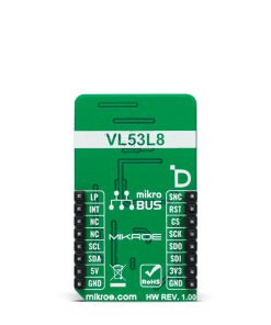
LightRanger 12 Click is based on the VL53L8CH, an 8×8 multizone Time-of-Flight (ToF) sensor from STMicroelectronics, designed for AI applications with exceptional performance under ambient light conditions. This sensor offers a wide 65° diagonal field of view (45° x 45° square), making it ideal for precise distance measurement and spatial mapping applications. It introduces a Compact and Normalized Histogram (CNH) data output format, specifically made for artificial intelligence applications that demand multizone raw data from a high-performance optical sensor, including AI-driven robotics, smart appliances like coffee machines and beverage dispensers, smart home solutions, and advanced recognition systems.

The VL53L8CH integrates a powerful new-generation Vertical-Cavity Surface-Emitting Laser (VCSEL) and two advanced metasurface lenses, enhancing its optical capabilities. The VCSEL emits an invisible 940 nm IR light that is Class 1 certified, ensuring eye safety while maintaining high performance. It also provides unparalleled flexibility by allowing users to configure up to 64 zones (8×8 grid), adjust histogram resolution to 128 bins, and define bin widths. Each zone’s infrared signal is transmitted to the host as raw histogram data, complementing the standard ToF sensor outputs, such as ranging distances up to 400 cm, signal levels, and reflectance.
By combining raw histogram data with traditional ranging capabilities, the VL53L8CH unlocks endless possibilities beyond standard distance measurement. It can detect and differentiate between solid materials like carpet, wood, glass, mirrors and fluids such as water, oil, or chemicals. This makes it possible to identify the location and size of a cup in coffee machines or beverage dispensers, detect floor materials for robotic navigation, or develop advanced AI-driven features like gesture motion recognition, hand posture detection, and even shape or motion analysis. Additionally, the sensor is suited for applications like people counting in smart homes and buildings.
Sensor data are accessed through the I2C or SPI interface, with a maximum frequency of 1MHz for I2C and 3MHz for SPI communication. The selection is made by positioning SMD jumpers labeled COMM SEL appropriately. Note that all the jumpers’ positions must be on the same side, or the Click board™ may become unresponsive.
In addition to the interface pins, this board uses several other pins. The SNC pin on the mikroBUS™ socket offers dual functionality: it can serve as a synchronization input, enabling the sensor to align its measurements with external events or signals for precise timing and coordination in applications requiring high accuracy, or it can act as a general-purpose open-drain input/output pin, providing added versatility for control or signaling tasks tailored to specific application needs. The LP pin allows users to toggle the I2C communication ON or OFF while in low-power mode, which is particularly useful for changing the I2C address in multi-device systems. Lastly, the INT pin provides an interrupt signal to indicate when a ranging measurement is available, ensuring data handling and real-time responsiveness.
The VL53L8CH does not require a specific Power-Up sequence but requires a voltage of 1.8V for its interface and logic part to work correctly. Therefore, a small regulating LDO, the AP2112, provides a 1.8V out of selected mikroBUS™ power rail. Since the sensor operates on 1.8V, this Click board™ also features the TXB0108E voltage-level translator, allowing the VL53L8CH to work properly with 3.3V and 5V MCU.
This Click board™ can operate with either 3.3V or 5V logic voltage levels selected via the VCC SEL jumper. This way, both 3.3V and 5V capable MCUs can use the communication lines properly. Also, this Click board™ comes equipped with a library containing easy-to-use functions and an example code that can be used as a reference for further development.
Specifications
Type
Optical
Applications
Ideal for AI applications, including robotics, coffee machines, smart homes, and advanced recognition systems
On-board modules
VL53L8CH – 8×8 multizone Time-of-Flight (ToF) sensor from STMicroelectronics
Key Features
Wide 65° diagonal FoV (45° x 45° square), ranging distance up to 400cm, supports up to 64 configurable zones (8×8 grid), Compact and Normalized Histogram (CNH) raw data and standard ToF outputs, I2C and SPI interfaces, 940nm IR laser with Class 1 eye safety certification, and more
Interface
I2C,SPI
Feature
ClickID
Compatibility
mikroBUS™
Click board size
M (42.9 x 25.4 mm)
Input Voltage
3.3V or 5V
Pinout diagram
This table shows how the pinout on LightRanger 12 Click corresponds to the pinout on the mikroBUS™ socket (the latter shown in the two middle columns).
| Notes | Pin | Pin | Notes | ||||
|---|---|---|---|---|---|---|---|
| Synchronization / GPIO | SNC | 1 | AN | PWM | 16 | LP | Low Power I2C Enable |
| ID SEL | RST | 2 | RST | INT | 15 | INT | Interrupt |
| SPI Select / ID COMM | CS | 3 | CS | RX | 14 | NC | |
| SPI Clock | SCK | 4 | SCK | TX | 13 | NC | |
| SPI Data OUT | SDO | 5 | MISO | SCL | 12 | SCL | I2C Clock |
| SPI Data IN | SDI | 6 | MOSI | SDA | 11 | SDA | I2C Data |
| Power Supply | 3.3V | 7 | 3.3V | 5V | 10 | 5V | Power Supply |
| Ground | GND | 8 | GND | GND | 9 | GND | Ground |
Onboard settings and indicators
| Label | Name | Default | Description |
|---|---|---|---|
| LD1 | PWR | – | Power LED Indicator |
| JP1 | VCC SEL | Left | Power Voltage Level Selection 3V3/5V: Left position 3V3, Right position 5V |
| JP2-JP5 | COMM SEL | Right | Communication Interface Selection SPI/I2C: Left position SPI, Right position I2C |
LightRanger 12 Click electrical specifications
| Description | Min | Typ | Max | Unit |
|---|---|---|---|---|
| Supply Voltage | 3.3 | – | 5 | V |
| Ranging | 2 | – | 400 | cm |
| Infrared Emitter | – | 940 | – | nm |
| Sample Rate | – | – | 60 | Hz |
Software Support
LightRanger 12 Click demo application is developed using the NECTO Studio, ensuring compatibility with mikroSDK‘s open-source libraries and tools. Designed for plug-and-play implementation and testing, the demo is fully compatible with all development, starter, and mikromedia boards featuring a mikroBUS™ socket.
Example Description
This example demonstrates the use of LightRanger 12 Click board by reading and displaying 8×8 zones measurements on the USB UART.
Key Functions
lightranger12_cfg_setupConfig Object Initialization function.lightranger12_initInitialization function.lightranger12_default_cfgClick Default Configuration function.lightranger12_get_int_pinThis function returns the INT (interrupt) pin logic state.lightranger12_get_resolutionThis function gets the current resolution (4×4 or 8×8).lightranger12_get_ranging_dataThis function gets the ranging data, using the selected output and the resolution.
Application Init
Initializes the driver and performs the Click default configuration.
Application Task
Reads all zone measurements approximately every 200ms and logs them to the USB UART as an 8×8 map. The silicon temperature measurement in degrees Celsius is also displayed.
Application Output
This Click board can be interfaced and monitored in two ways:
- Application Output – Use the “Application Output” window in Debug mode for real-time data monitoring. Set it up properly by following this tutorial.
- UART Terminal – Monitor data via the UART Terminal using a USB to UART converter. For detailed instructions, check out this tutorial.
Additional Notes and Information
The complete application code and a ready-to-use project are available through the NECTO Studio Package Manager for direct installation in the NECTO Studio. The application code can also be found on the MIKROE GitHub account.
Resources
Downloads
| Weight | 18 g |
|---|---|
| Brand | MikroElektronika |