How does it work?
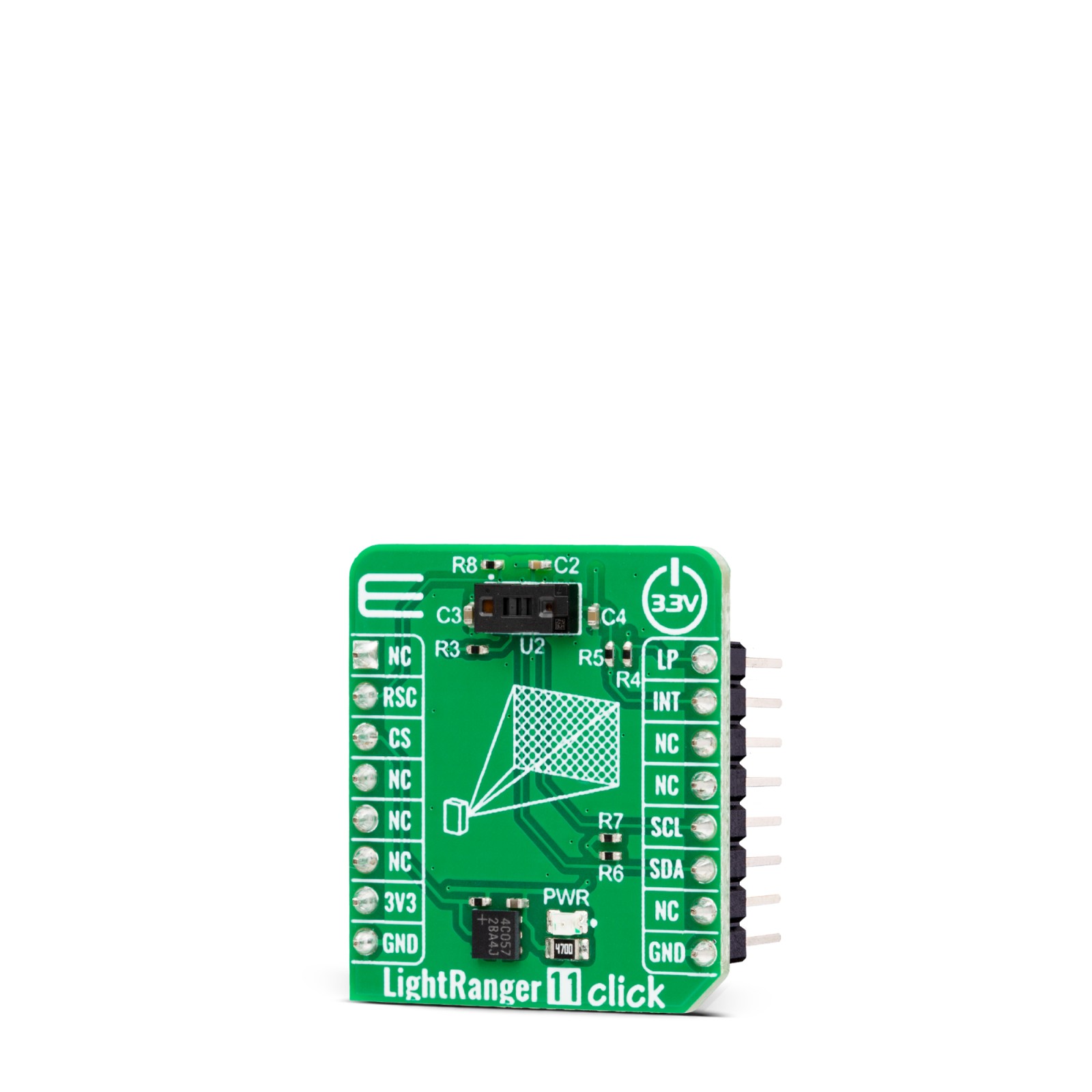
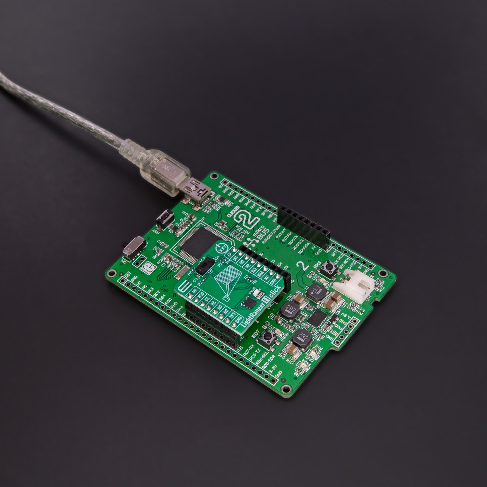
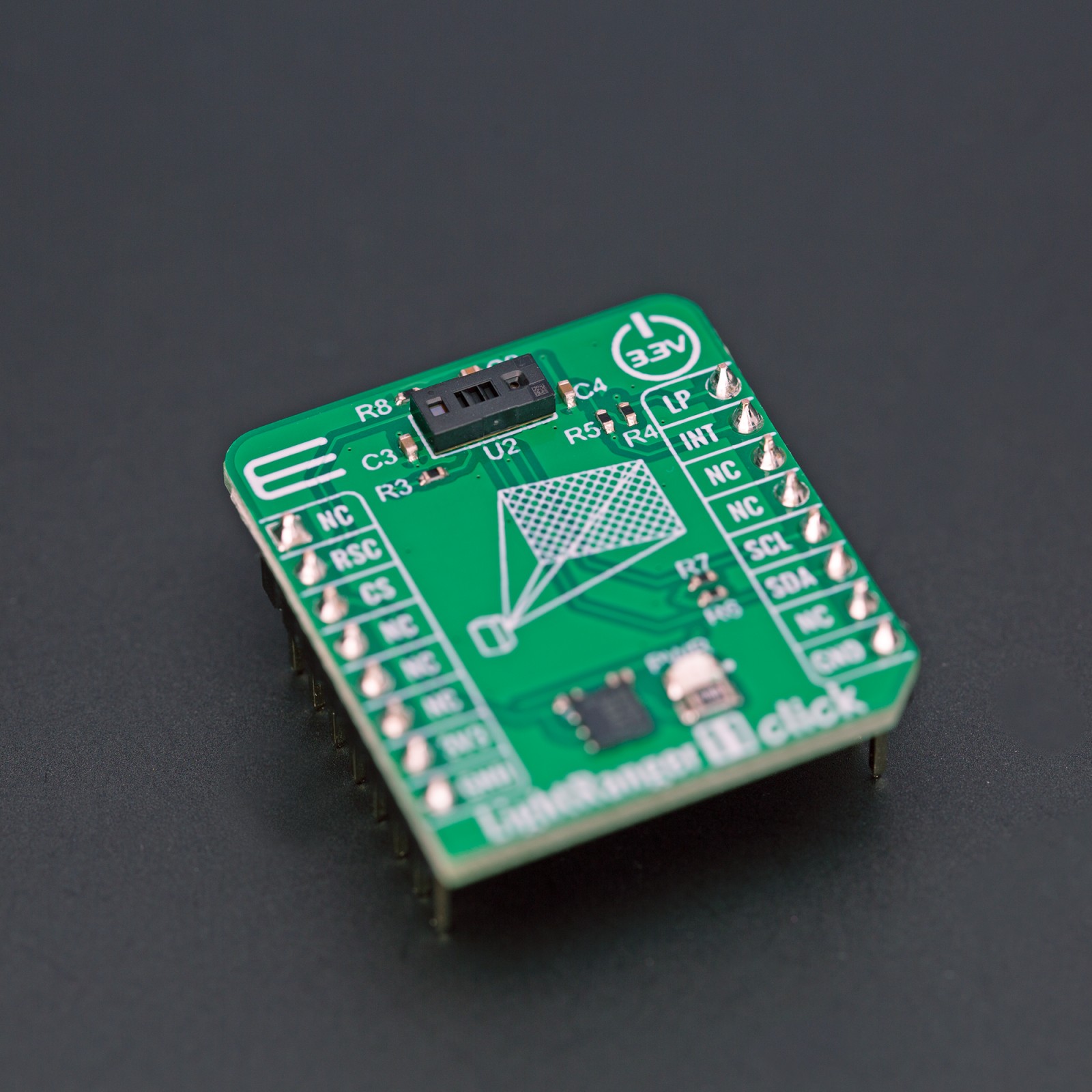
LightRanger11 Click is based on the VL53L7CX, a time-of-flight 8×8 multizone ranging sensor from STMicroelectronics. This ToF sensor integrates a VCSEL (vertical-cavity surface-emitting laser), which emits an entirely invisible 940nm IR light, totally safe for eyes (Class 1 certification), and a SPAD (single-photon avalanche diode) array which helps the VL53L7CX to achieve the best-ranging performance even when a Click board™ is hidden behind a wide range of cover glass materials. In addition, the sensor is equipped with diffractive optical elements (DOE) on both the transmitter and the receiver, enabling square FoV.
Designed explicitly for small-range and multi-target measurements, the VL53L7CX provides very accurate distance measurements up to 350cm with excellent results over short distances and 60° x 60° square field of view (FoV) (90° diagonal), which improves performances under ambient light. Thanks to ST’s patented algorithms, the VL53L7CX can detect multiple objects within the FoV with depth understanding. ST histogram algorithms ensure cover glass crosstalk immunity beyond 60cm. Like all Time-of-Flight sensors based on ST’s FlightSense technology, the VL53L7CX records an absolute distance measurement regardless of the target color and reflectance.
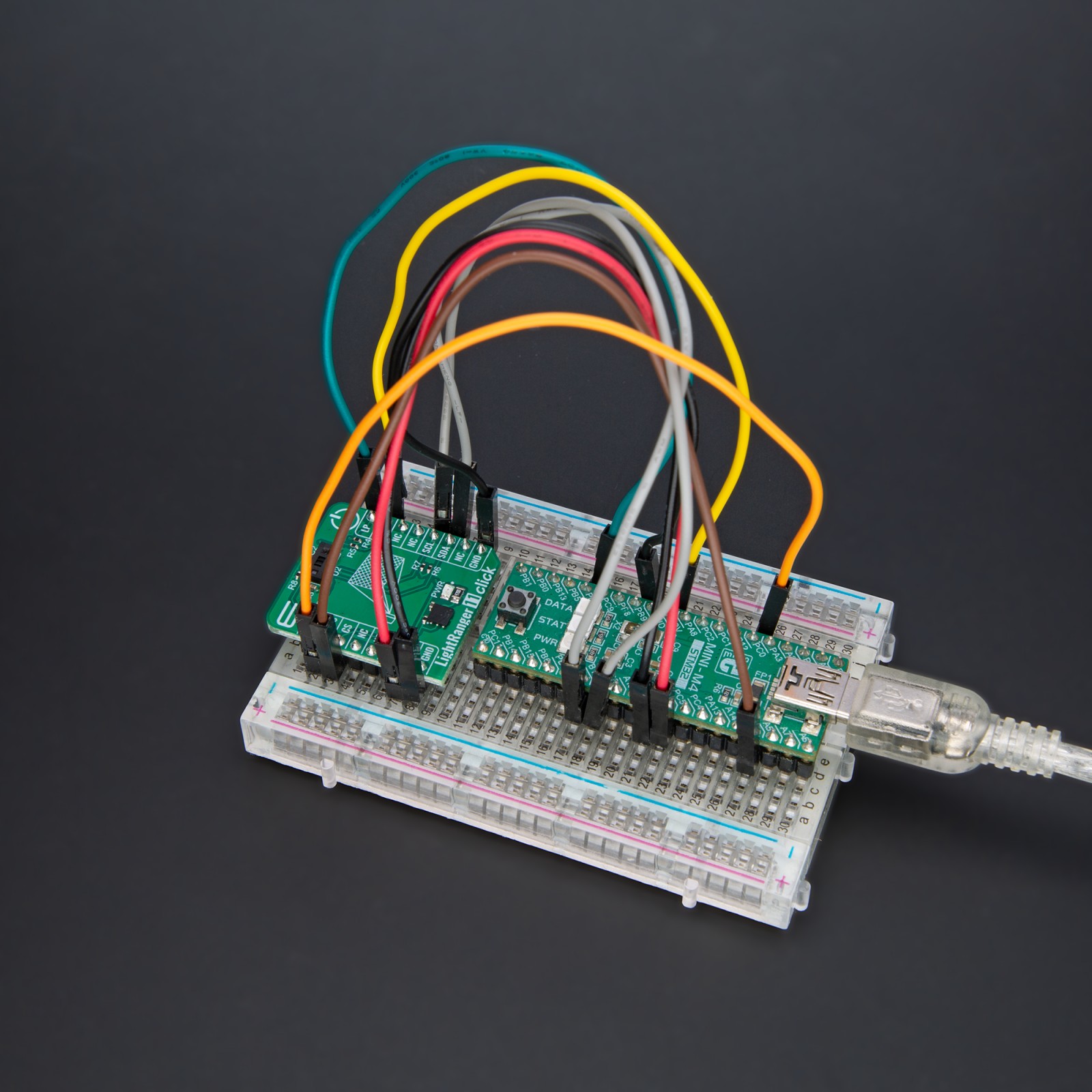
LightRanger 11 Click uses a standard 2-Wire I2C interface to communicate with the host MCU, read data, and configure settings with a maximum clock frequency of up to 1MHz. The I2C interface on Click board™ can be reset through the RSC pin of the mikroBUS™ socket, hence offering a switch operation to turn ON the initial I2C starting sequence of the VL53L7CX. It also possesses an additional interrupt pin, routed to the INT pin on the mikroBUS™ socket, indicating when a ranging measurement is available. An LP pin lets you turn the I2C communication on or off when in low power mode, which is used when it is required to change the I2C address in multi-device systems.
This Click board™ can be operated only with a 3.3V logic voltage level. The board must perform appropriate logic voltage level conversion before using MCUs with different logic levels. Also, this Click board™ comes equipped with a library containing easy-to-use functions and an example code that can be used as a reference for further development.
Specifications
Type
Optical
Applications
Can be used for the development of presence (object) detection applications, distance measurement, industrial ranging, inventory control, and many other applications
On-board modules
VL53L7CX – time-of-flight 8×8 multizone ranging sensor from STMicroelectronics
Key Features
Multizone ranging output with either 4×4 or 8×8 separate zones, multitarget detection and distance measurement in each zone, histogram processing and algorithmic compensation, motion indicator for each zone, and more
Interface
I2C
Feature
ClickID
Compatibility
mikroBUS™
Click board size
S (28.6 x 25.4 mm)
Input Voltage
3.3V
Pinout diagram
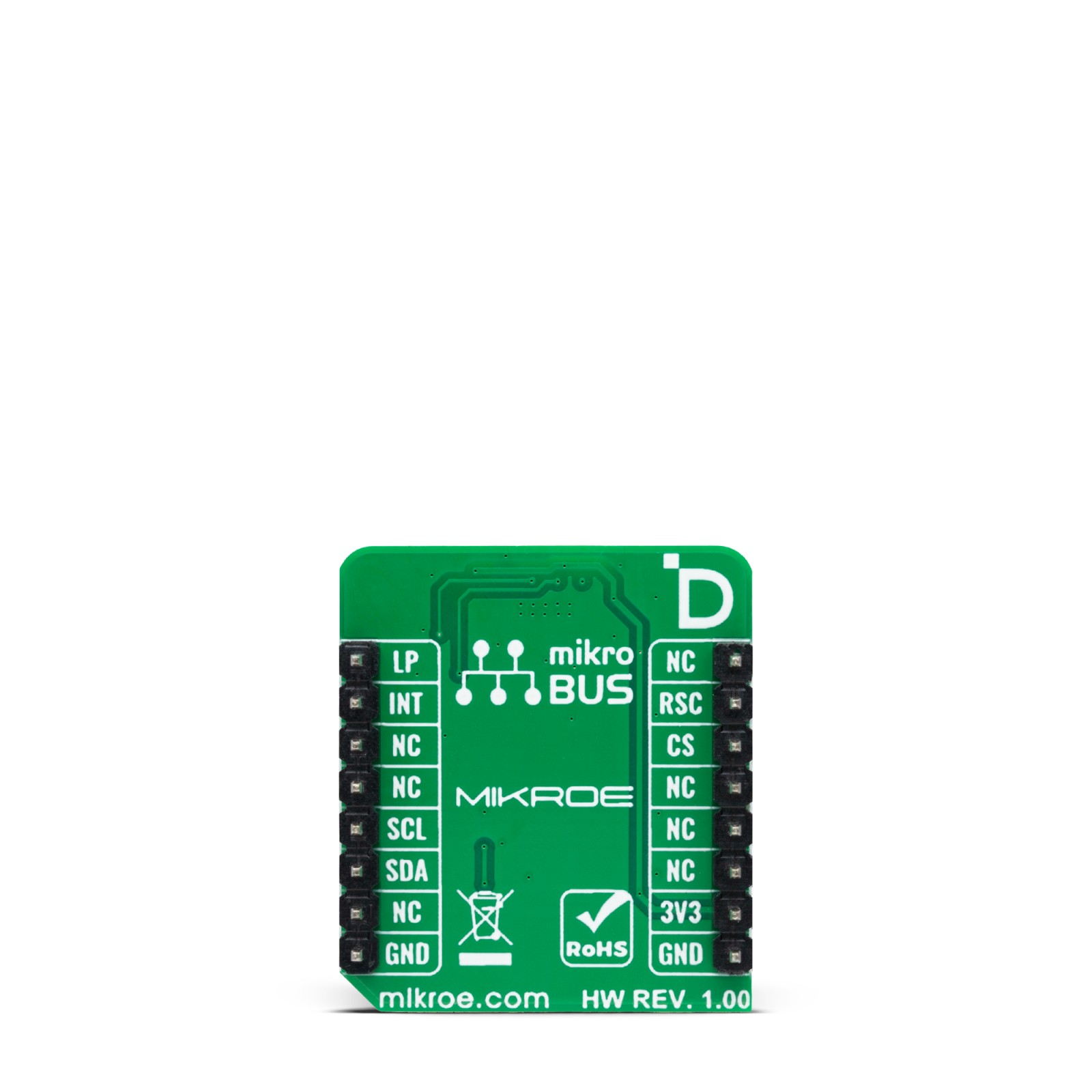
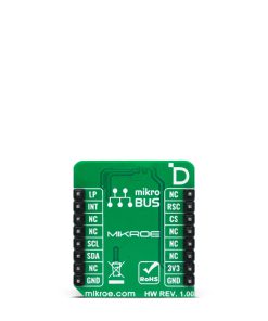
This table shows how the pinout on LightRanger 11 Click corresponds to the pinout on the mikroBUS™ socket (the latter shown in the two middle columns).
Onboard settings and indicators
Label | Name | Default | Description |
---|---|---|---|
LD1 | PWR | – | Power LED Indicator |
LightRanger 11 Click electrical specifications
Description | Min | Typ | Max | Unit |
---|---|---|---|---|
Supply Voltage | – | 3.3 | – | V |
Distance Measurement Range | 0 | – | 350 | cm |
Field of View | – | 90 | – | deg |
VCSEL Wavelength | – | 940 | – | nm |
Software Support
We provide a library for the LightRanger 11 Click as well as a demo application (example), developed using MIKROE compilers. The demo can run on all the main MIKROE development boards.
Package can be downloaded/installed directly from NECTO Studio Package Manager (recommended), downloaded from our LibStock™ or found on Mikroe github account.
Library Description
This library contains API for LightRanger 11 Click driver.
Key functions
-
lightranger11_get_ranging_data
LightRanger 11 get ranging data function. -
lightranger11_get_resolution
LightRanger 11 get resolution function. -
lightranger11_get_int_pin
LightRanger 11 get int pin function.
Example Description
This example demonstrates the use of LightRanger 11 Click board™ by reading and displaying 8×8 zones measurements on the USB UART.
void application_task ( void )
{
if ( !lightranger11_get_int_pin ( &lightranger11 ) )
{
lightranger11_results_data_t results;
uint8_t resolution, map_side;
err_t error_flag = lightranger11_get_resolution ( &lightranger11, &resolution );
error_flag |= lightranger11_get_ranging_data ( &lightranger11, &results );
if ( LIGHTRANGER11_OK == error_flag )
{
map_side = ( LIGHTRANGER11_RESOLUTION_4X4 == resolution ) ? 4 : 8;
log_printf ( &logger, "rn %ux%u MAP (mm):rn", ( uint16_t ) map_side, ( uint16_t ) map_side );
for ( uint16_t cnt = 1; cnt <= resolution; cnt++ )
{
log_printf ( &logger, " %ut", results.distance_mm[ cnt - 1 ] );
if ( 0 == ( cnt % map_side ) )
{
log_printf ( &logger, "rn" );
}
}
log_printf ( &logger, " Silicon temperature : %d degCrn", ( int16_t ) results.silicon_temp_degc );
}
}
}
The full application code, and ready to use projects can be installed directly from NECTO Studio Package Manager (recommended), downloaded from our LibStock™ or found on Mikroe github account.
Other Mikroe Libraries used in the example:
- MikroSDK.Board
- MikroSDK.Log
- Click.LightRanger11
Additional notes and informations
Depending on the development board you are using, you may need USB UART click, USB UART 2 Click or RS232 Click to connect to your PC, for development systems with no UART to USB interface available on the board. UART terminal is available in all MIKROE compilers.
mikroSDK
This Click board™ is supported with mikroSDK – MIKROE Software Development Kit. To ensure proper operation of mikroSDK compliant Click board™ demo applications, mikroSDK should be downloaded from the LibStock and installed for the compiler you are using.
For more information about mikroSDK, visit the official page.