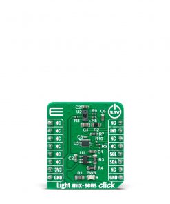
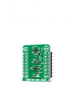
Light mix-sens Click
R245.00 ex. VAT
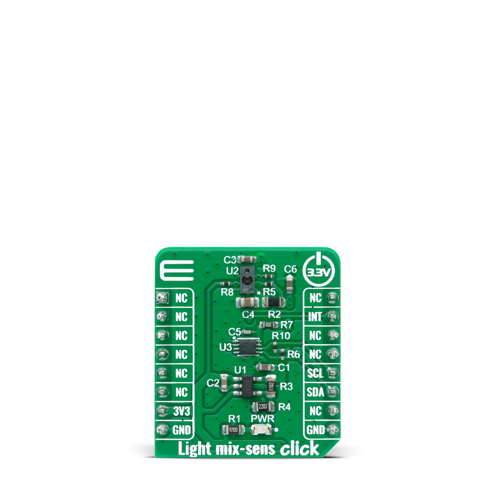
Light mix-sens Click is carrying TMD37253, an advanced proximity measurement, color sense (RGBC+IR), and digital ambient light sensing (ALS) device. The TMD37253 slim module package has been designed to accommodate a “single hole” aperture approach that incorporates an IR LED and factory calibrated LED driver. The proximity detection feature provides object detection (e.g., mobile device screen to the user’s ear) by photodiode detection of reflected IR energy (sourced by the integrated LED). The ALS detection feature provides photopic light intensity data. The color photodiodes have UV and IR blocking filters and a dedicated data converters producing 16-bit data. This architecture allows applications to accurately measure ambient light which enables devices to calculate illuminance and color temperature to control display backlight and chromaticity.
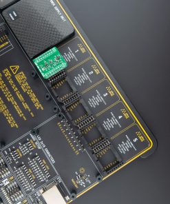
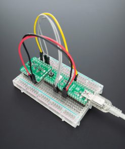
Light mix-sens Click board™ is supported by a mikroSDK compliant library, which includes functions that simplify software development. This Click board™ comes as a fully tested product, ready to be used on a system equipped with the mikroBUS™ socket.
Stock: Lead-time applicable.
| 5+ | R232.75 |
| 10+ | R220.50 |
| 15+ | R208.25 |
| 20+ | R200.41 |
How does it work?
Light mix-sens Click features advanced proximity measurement, color sense (RGBC+IR), and digital ambient light sensing (ALS). The TMD37253 slim module, from AMS, incorporates an IR LED and factory calibrated LED driver. The proximity detection feature provides object detection (e.g. mobile device screen to the user’s ear) by photodiode detection of reflected IR energy (sourced by the integrated LED). Detect/release events are interrupt-driven, and occur when proximity result crosses upper and/or lower threshold settings. The proximity engine features offset adjustment registers to compensate for unwanted IR energy reflection at the sensor. Proximity results are further improved by automatic ambient light subtraction. The ALS detection feature provides photopic light intensity data. The color photodiodes have UV and IR blocking filters and a dedicated data converters producing 16-bit data. This architecture allows applications to accurately measure ambient light which enables devices to calculate illuminance and color temperature to control display backlight and chromaticity.

Proximity results are affected by three fundamental factors: the integrated IR LED emission, IR reception, and environmental factors, including target distance and surface reflectivity. The IR reception signal path begins with IR detection from a photodiode and ends with the 8-bit proximity result in the PDATA register. A signal from the photodiode is amplified, and offset adjusted to optimize performance. Offset correction or cross-talk compensation is accomplished by adjustment to the POFFSET register. The analog circuitry of the device applies the offset value as a subtraction to the signal accumulation; therefore a positive offset value has the effect of decreasing the results.
The color and ALS reception signal path begins as photodiodes receive filtered light and ends with 16-bit results. The IR photodiode primarily used for proximity sensing is multiplexed with the green channel’s ADC to measure the IR content of ambient light. The color photodiodes are filtered with UV and IR filters. The IR photodiode is filtered to receive only IR. A signal from the RGBC photodiodes simultaneously accumulate for a period of time set by the value in ATIME before the results are available. Measurement of IR must be done in a separate integration because it shares the ADC with the green photodiode. Gain is adjustable from 1x to 128 x to facilitate the operation over a wide range of lighting conditions. Custom LUX equations are used to calculate the amount of ambient light, color temperature, as well as, determine the light type (e.g. LED, fluorescent, incandescent, etc.) using the ALS results.
The TMD37253 module operates at 1.8V power supply with 1.8V I2C bus for reduced power consumption. For integration on Mikrobus, complete voltage regulation and logic level translation has been implemented. Therefore, this Click Board™ is designed to be operated only with a 3.3V logic level. A proper logic voltage level conversion should be performed before the Click board™ is used with MCUs with logic levels of 5V.
Specifications
Type
Optical
Applications
Can be used for ambient light sensing, single hole proximity sensing, mobile phone touch screen disable, color temperature sensing to assist backlight, camera, and flash control.
On-board modules
Light mix-sens Click uses the TMD37253 IC, an advanced proximity measurement, color sense (RGBC+IR), and digital ambient light sensing (ALS) device, from AMS.
Key Features
Accurate color temperature and ambient light sensing, UV / IR blocking filters, 46° Average FOV, Photopic ambient light sensing (ALS), Programmable gain and integration time, Reduced power consumption.
Interface
I2C
Feature
No ClickID
Compatibility
mikroBUS™
Click board size
S (28.6 x 25.4 mm)
Input Voltage
3.3V
Pinout diagram
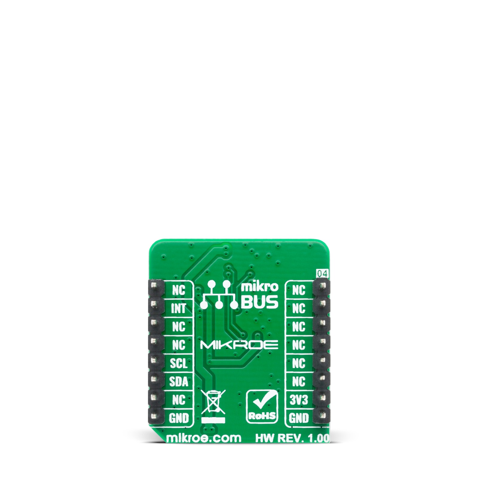
This table shows how the pinout on Light mix-sens Click corresponds to the pinout on the mikroBUS™ socket (the latter shown in the two middle columns).
Onboard settings and indicators
| Label | Name | Default | Description |
|---|---|---|---|
| LD1 | PWR | – | Power LED Indicator |
Software Support
We provide a library for the Light mix-sens Click on our LibStock page, as well as a demo application (example), developed using MikroElektronika compilers. The demo can run on all the main MikroElektronika development boards.
Library Description
This library allows user to perform a communication with the Light mix-sens Click board. The user can measure the full spectral of light together with proximity measurement. By switching an IR diode, one of two possible IR measurements can be executed, the level of IR light can be measured, or the proximity, together with the all other channels. For more details, please, check the full documentation.
Key functions:
lightmixsens_err_t lightmixsens_write_byte( uint8_t reg_addr, uint8_t data_in );– This function writes data byte to the selected register.lightmixsens_err_t lightmixsens_read_byte( uint8_t reg_addr, uint8_t *data_out );– This function reads data byte from the selected register.void lightmixsens_switch_ir_to_green( void );– This function switches the IR light to be measured in the Green channel (GDATA) register.
Examples description
The application is composed of three sections :
- System Initialization – Initializes all necessary peripherals and pins.
- Application Initialization – Initializes I2C driver and performs the Click board default configuration to allow ALS/Color and Proximity measurements.
- Application Task – (code snippet) – Waits until ALS/Color integration cycle was done and then reads the entire measurement. The all results will be sent to the selected UART terminal.
void application_task( )
{
    lightmixsens_wait_atime( );

    lightmixsens_read_word( LIGHTMIXSENS_REG_CDATA, &lightmixsens_cdata );
    lightmixsens_read_word( LIGHTMIXSENS_REG_RDATA, &lightmixsens_rdata );
    lightmixsens_read_word( LIGHTMIXSENS_REG_GDATA_IRDATA, &lightmixsens_gdata );
    lightmixsens_read_word( LIGHTMIXSENS_REG_BDATA, &lightmixsens_bdata );
    lightmixsens_read_byte( LIGHTMIXSENS_REG_PDATA, &lightmixsens_pdata );

    WordToStr( lightmixsens_cdata, log_txt );
    Ltrim( log_txt );
    mikrobus_logWrite( "- Clear light:  ", _LOG_TEXT );
    mikrobus_logWrite( log_txt, _LOG_TEXT );
    mikrobus_logWrite( " lx", _LOG_LINE );

    WordToStr( lightmixsens_rdata, log_txt );
    Ltrim( log_txt );
    mikrobus_logWrite( "- Red light:    ", _LOG_TEXT );
    mikrobus_logWrite( log_txt, _LOG_TEXT );
    mikrobus_logWrite( " lx", _LOG_LINE );

    WordToStr( lightmixsens_gdata, log_txt );
    Ltrim( log_txt );
    mikrobus_logWrite( "- Green light:  ", _LOG_TEXT );
    mikrobus_logWrite( log_txt, _LOG_TEXT );
    mikrobus_logWrite( " lx", _LOG_LINE );

    WordToStr( lightmixsens_bdata, log_txt );
    Ltrim( log_txt );
    mikrobus_logWrite( "- Blue light:   ", _LOG_TEXT );
    mikrobus_logWrite( log_txt, _LOG_TEXT );
    mikrobus_logWrite( " lx", _LOG_LINE );

    prox_app( );
    mikrobus_logWrite( "** Proximity:   ", _LOG_TEXT );
    mikrobus_logWrite( log_txt, _LOG_LINE );

    mikrobus_logWrite( "", _LOG_LINE );
}
Additional Functions :
- prox_app – This is application function which determines the proximity results.
The full application code, and ready to use projects can be found on our LibStock page.
Other mikroE Libraries used in the example:
- Conversions
- C_String
- I2C
- UART
Additional notes and informations
Depending on the development board you are using, you may need USB UART click, USB UART 2 click or RS232 click to connect to your PC, for development systems with no UART to USB interface available on the board. The terminal available in all MikroElektronika compilers, or any other terminal application of your choice, can be used to read the message.
mikroSDK
This Click board™ is supported with mikroSDK – MikroElektronika Software Development Kit. To ensure proper operation of mikroSDK compliant Click board™ demo applications, mikroSDK should be downloaded from the LibStock and installed for the compiler you are using.
For more information about mikroSDK, visit the official page.
Resources
Downloads
| Weight | 15 g |
|---|---|
| Brand | MikroElektronika |

