How does it work?
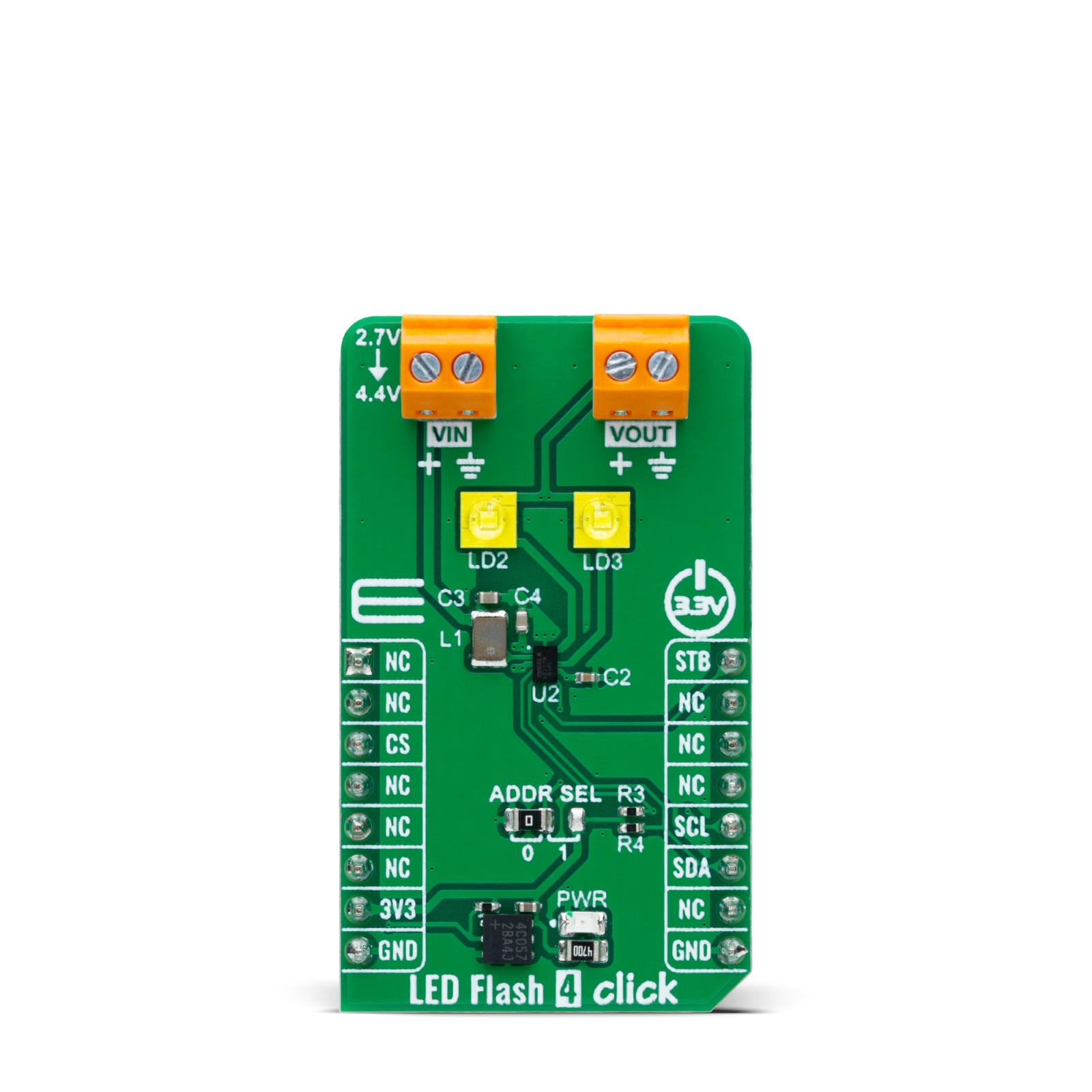
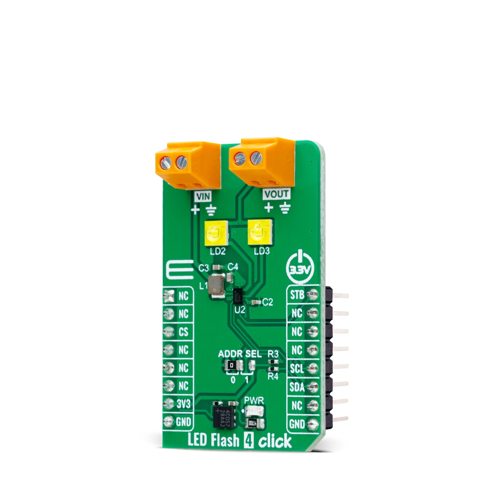
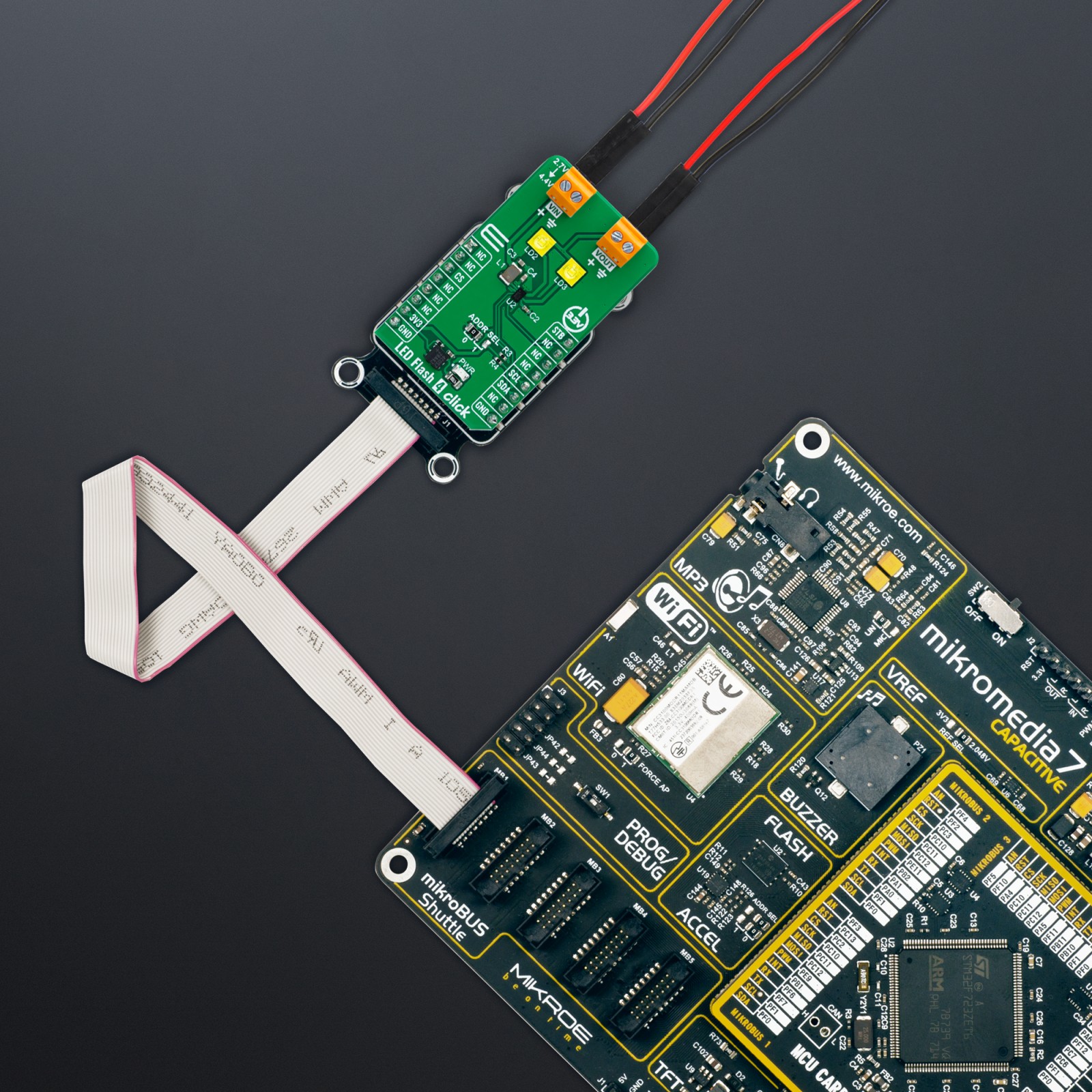
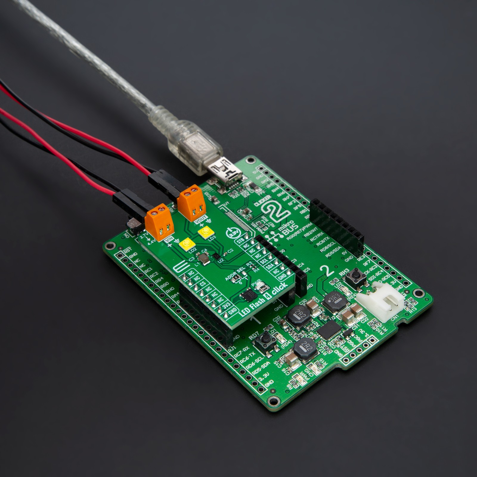
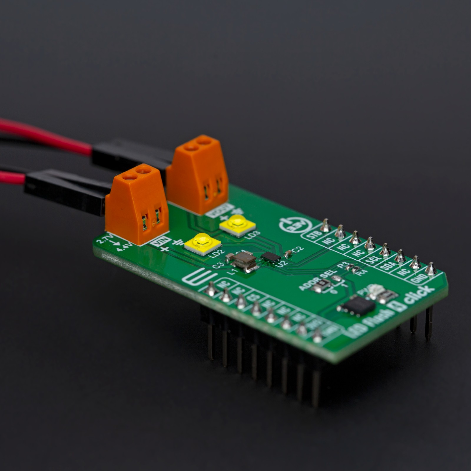
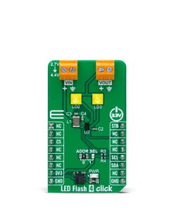
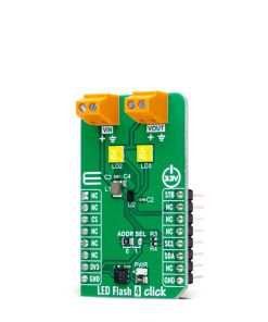
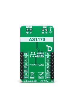
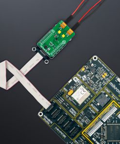
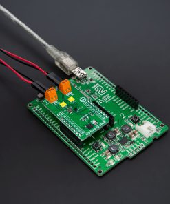
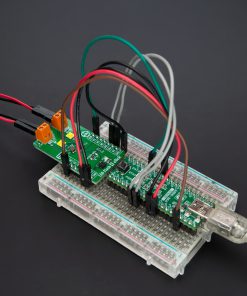
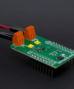
LED Flash 4 Click is based on the AS1170, a high-current LED driver from ams OSRAM, designed for high-performance LED flash and torch applications. The AS1170 is an inductive, highly efficient DC-DC step-up converter that operates with an external power supply from 2.7V up to 4.4V at a fixed frequency of 4MHz. It includes two internal current sinks, enabling the independent control of two onboard flash LEDs (XPCWHT-L1-R250-00A01), which deliver exceptional light quality. With its soft Start-Up feature, the AS1170 integrates easily into noise-sensitive RF systems. This chip has several protection functions, including flash timeout, overvoltage, overtemperature, undervoltage, and short circuit protection, ensuring reliable operation even in demanding environments. This Click board™ is ideal for use as a flash or torch, providing significant advantages such as precise control over LED brightness and extended battery life due to the efficient power conversion.
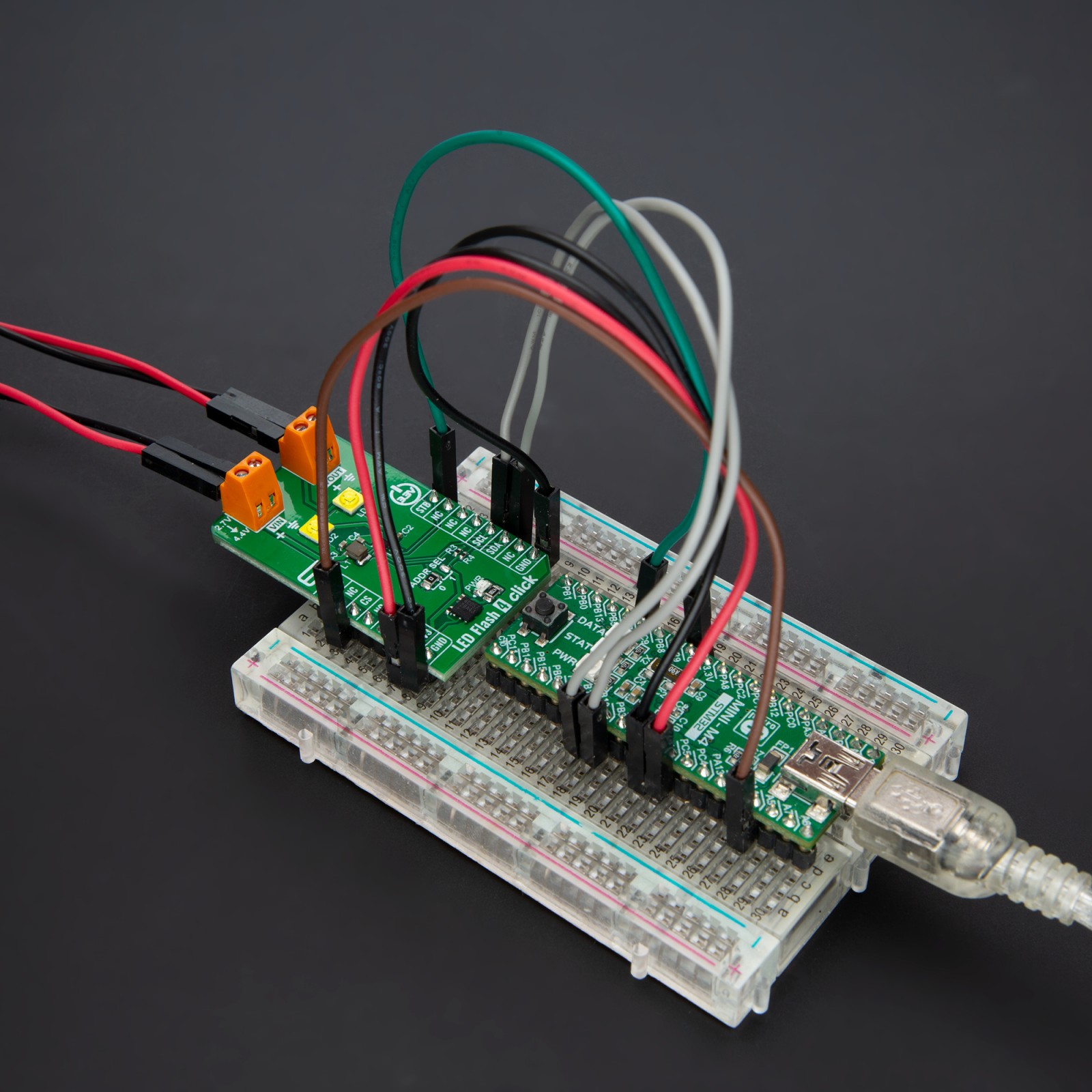
LED Flash 4 Click uses a standard 2-wire I2C communication protocol, allowing the host MCU to control the AS1170 with ease. The I2C interface supports clock frequencies up to 400kHz, with the I2C address selectable via the onboard ADDR SEL jumpers, providing flexibility in communication setup. Additionally, the board features an STB (strobe) pin and a digital signal with a pulldown resistor, which controls the strobe time for the flash function, enabling precise timing and synchronization of the LED flash. The AS1170 also incorporates a hardware automatic shutdown mode that activates if no I2C clock signal is detected for 100ms, eliminating the need for an additional enable input to power down the device when the system shuts down.
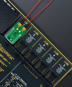
Besides a VIN terminal for external supplying the AS1170, the board also includes a VOUT terminal that allows the AS1170 to power a 5V system, such as an audio amplifier. This operating mode can be selected via the I2C interface by setting the corresponding register bit (const_v_mode=1). In this mode, the current sinks are disabled, and the LEDs cannot be switched on, making it suitable for powering external devices.
This Click board™ can be operated only with a 3.3V logic voltage level. The board must perform appropriate logic voltage level conversion before using MCUs with different logic levels. Also, it comes equipped with a library containing functions and an example code that can be used as a reference for further development.
Specifications
Type
LED Segment
Applications
Ideal for applications requiring precise LED brightness control and extended battery life, such as portable flashlights and camera flashes
On-board modules
AS1170 – high-current LED driver from ams OSRAM
Key Features
High-current LED driver, fixed 4MHz frequency, two onboard flash LEDs, independent control of LEDs, soft Start-Up, protection features, I2C interface, strobe control, automatic shutdoen, terminal for external system powering with 5V, and more
Interface
I2C
Feature
ClickID
Compatibility
mikroBUS™
Click board size
M (42.9 x 25.4 mm)
Input Voltage
3.3V,External
Pinout diagram
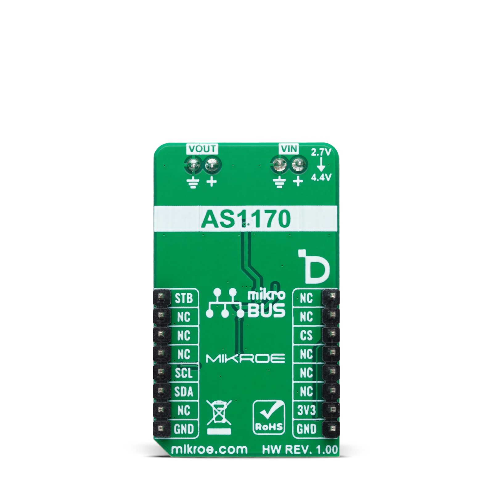
This table shows how the pinout on LED Flash 4 Click corresponds to the pinout on the mikroBUS™ socket (the latter shown in the two middle columns).
Onboard settings and indicators
Label | Name | Default | Description |
---|---|---|---|
LD1 | PWR | – | Power LED Indicator |
LD2-LD3 | LD2-LD3 | – | Flash/Torch LEDs |
JP1 | ADDR SEL | Left | I2C Address Selection 0/1: Left position 0, Right position 1 |
LED Flash 4 Click electrical specifications
Description | Min | Typ | Max | Unit |
---|---|---|---|---|
Supply Voltage | – | 3.3 | – | V |
External Power Supply | 2.7 | – | 4.4 | V |
Output Voltage | – | 5 | – | V |
Software Support
We provide a library for the LED Flash 4 Click as well as a demo application (example), developed using MIKROE compilers. The demo can run on all the main MIKROE development boards.
Package can be downloaded/installed directly from NECTO Studio Package Manager (recommended), downloaded from our LibStock™ or found on MIKROE github account.
Library Description
This library contains API for LED Flash 4 Click driver.
Key functions
-
ledflash4_set_led1_current
This function sets the LED1 maximum current in mA. -
ledflash4_set_led2_current
This function sets the LED2 maximum current in mA. -
ledflash4_set_stb_pin
This function sets the strobe (STB) pin logic state.
Example Description
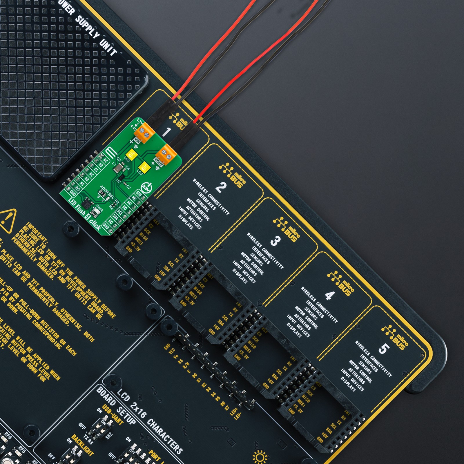
This example demonstrates the use of LED Flash 4 Click board™ by toggling the LEDs output.
void application_task ( void )
{
log_printf( &logger, " LEDs ONrnn" );
ledflash4_set_stb_pin ( &ledflash4, LEDFLASH4_STROBE_PIN_HIGH );
Delay_ms ( 1000 );
Delay_ms ( 1000 );
log_printf( &logger, " LEDs OFFrnn" );
ledflash4_set_stb_pin ( &ledflash4, LEDFLASH4_STROBE_PIN_LOW );
Delay_ms ( 1000 );
Delay_ms ( 1000 );
}
The full application code, and ready to use projects can be installed directly from NECTO Studio Package Manager (recommended), downloaded from our LibStock™ or found on MIKROE github account.
Other MIKROE Libraries used in the example:
- MikroSDK.Board
- MikroSDK.Log
- Click.LEDFlash4
Additional notes and informations
Depending on the development board you are using, you may need USB UART click, USB UART 2 Click or RS232 Click to connect to your PC, for development systems with no UART to USB interface available on the board. UART terminal is available in all MIKROE compilers.
mikroSDK
This Click board™ is supported with mikroSDK – MIKROE Software Development Kit. To ensure proper operation of mikroSDK compliant Click board™ demo applications, mikroSDK should be downloaded from the LibStock and installed for the compiler you are using.
For more information about mikroSDK, visit the official page.