HOW DOES IT WORK?
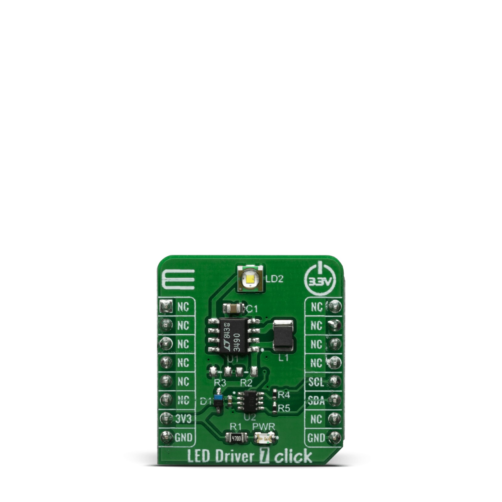
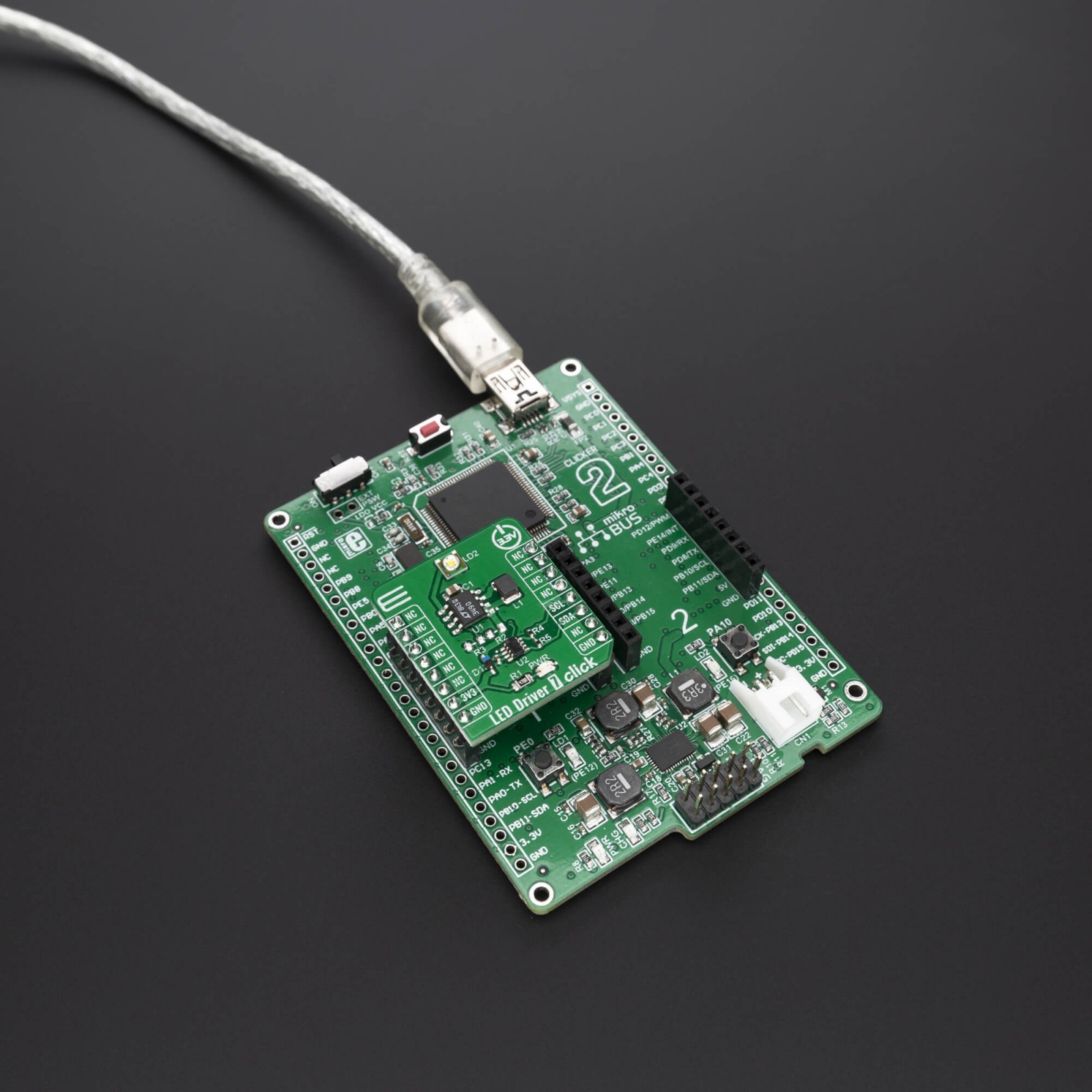
LED Driver 7 click features the LTC3490, single cell 350mA LED driver from Analog Devices. It provides a constant current drive for 1W LED applications. It is a high efficiency boost converter. Some of its key features include the 350mA Constant Current Output, Fixed Frequency Operation: 1.3MHz, Low Quiescent Current: <1mA and Dimming Control.
The LED Driver 7 click also features the AD5171, a 64-position OTP digital potentiometer from Analog Devices. The AD5171 is used for changing the voltage on the CTRL/SHDN pin. This voltage can control the LED drive current from 0mA to 350mA. The AD5171 uses fuse link technology to achieve the memory retention of the resistance setting function. OTP is a cost-effective alternative over the EEMEM approach for users who do not need to reprogram new memory settings in the digital potentiometer. This device performs the same electronic adjustment function as most mechanical trimmers and variable resistors. The AD5171 is programmed using a 2-wire, I2 C®- compatible digital control. It allows unlimited adjustments before permanently setting the resistance value. During the OTP activation, a permanent fuse blown command is sent after the final value is determined, freezing the wiper position at a given setting (analogous to placing epoxy on a mechanical trimmer).
Given the options its features offer, the LED Driver 7 click is ideally used for Portable lighting, rechargeable flashlights, system calibrations, electronics level settings, automotive electronics adjustments, mechanical trimmers and potentiometer replacements.
This Click Board™ is designed to be operated only with 3.3V logic level. A proper logic voltage level conversion should be performed before the Click board™ is used with MCUs with logic levels of 5V.
Specifications
Type
LED Drivers
Applications
Portable lighting, rechargeable flashlights, system calibrations, electronics level settings, automotive electronics adjustments, mechanical trimmers and potentiometer replacements
On-board modules
LTC3490, single cell 350mA LED driver from Analog Devices AD5171, a 64-position OTP digital potentiometer also from Analog Devices
Key Features
Dimming Control, 350mA Constant Current Output, I2C-compatible digital interface
Interface
I2C
Feature
No ClickID
Compatibility
mikroBUS™
Click board size
S (28.6 x 25.4 mm)
Input Voltage
3.3V
Pinout diagram
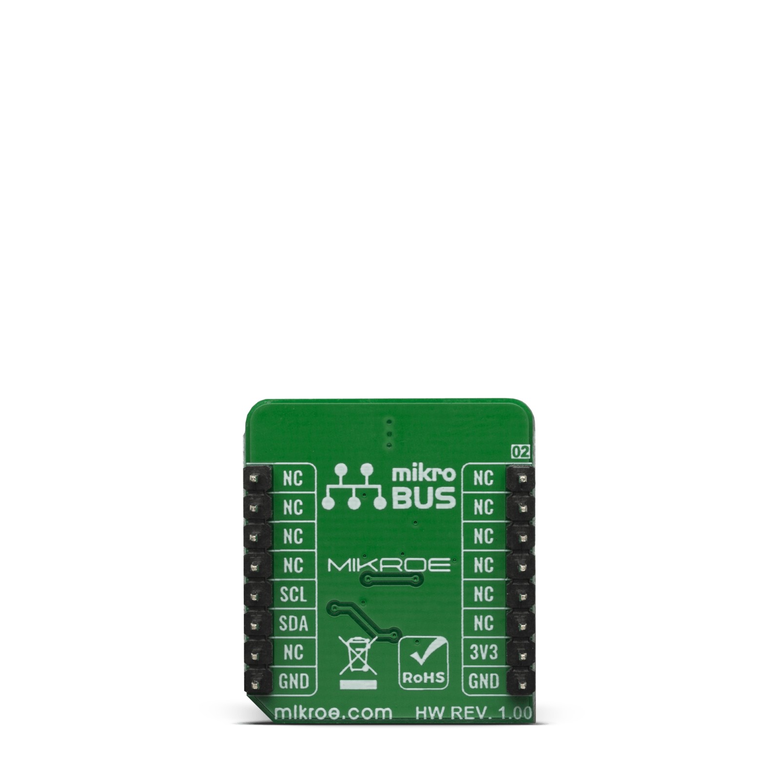
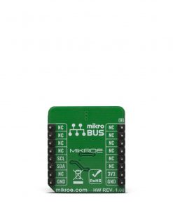
This table shows how the pinout on LED Driver 7 click corresponds to the pinout on the mikroBUS™ socket (the latter shown in the two middle columns).
Onboard settings and indicators
Label | Name | Default | Description |
---|---|---|---|
LD1 | PWR | – | Power LED Indicator |
Software Support
We provide a library for the LED Driver 7 Click on our LibStock page, as well as a demo application (example), developed using MikroElektronika compilers. The demo can run on all the main MikroElektronika development boards.
Library Description
Library provides full control of the LED’s illumination. User can change the LED’s brightness and apply “One Time Programming” with write function, or check the wiper and OTB bits with read function.
Key functions:
void leddriver7_write ( uint8_t cmd_byte, uint8_t pos );
– Function sets command byte and potentiometer position.uint8_t leddriver7_read ( );
– Function reads single byte of data from output register.
Examples description
The application is composed of three sections :
- System Initialization – Initializes I2Ca nd LOG modules.
- Application Initialization – Initalizes I2C driver and writes an initial log.
- Application Task – This example demonstrates the use of LED Driver 7 Click board, by cycling wiper positions of AD5171 Digital Potentiometer.
void application_task ( ) { for ( n_pos = 12; n_pos < pos_num; n_pos++ ) { leddriver7_write ( LEDDRIVER7_NORM_OP_MODE, n_pos ); ByteToStr( n_pos, test_log ); mikrobus_logWrite( "Position :", _LOG_TEXT ); mikrobus_logWrite( test_log, _LOG_LINE ); Delay_ms( 500 ); } }
The full application code, and ready to use projects can be found on our LibStock page.
Other mikroE Libraries used in the example:
- I2C
- UART
- Conversions
Additional notes and informations
Depending on the development board you are using, you may need USB UART click, USB UART 2 click or RS232 click to connect to your PC, for development systems with no UART to USB interface available on the board. The terminal available in all MikroElektronika compilers, or any other terminal application of your choice, can be used to read the message.
mikroSDK
This Click board™ is supported with mikroSDK – MikroElektronika Software Development Kit. To ensure proper operation of mikroSDK compliant Click board™ demo applications, mikroSDK should be downloaded from the LibStock and installed for the compiler you are using.
For more information about mikroSDK, visit the official page.