How does it work?
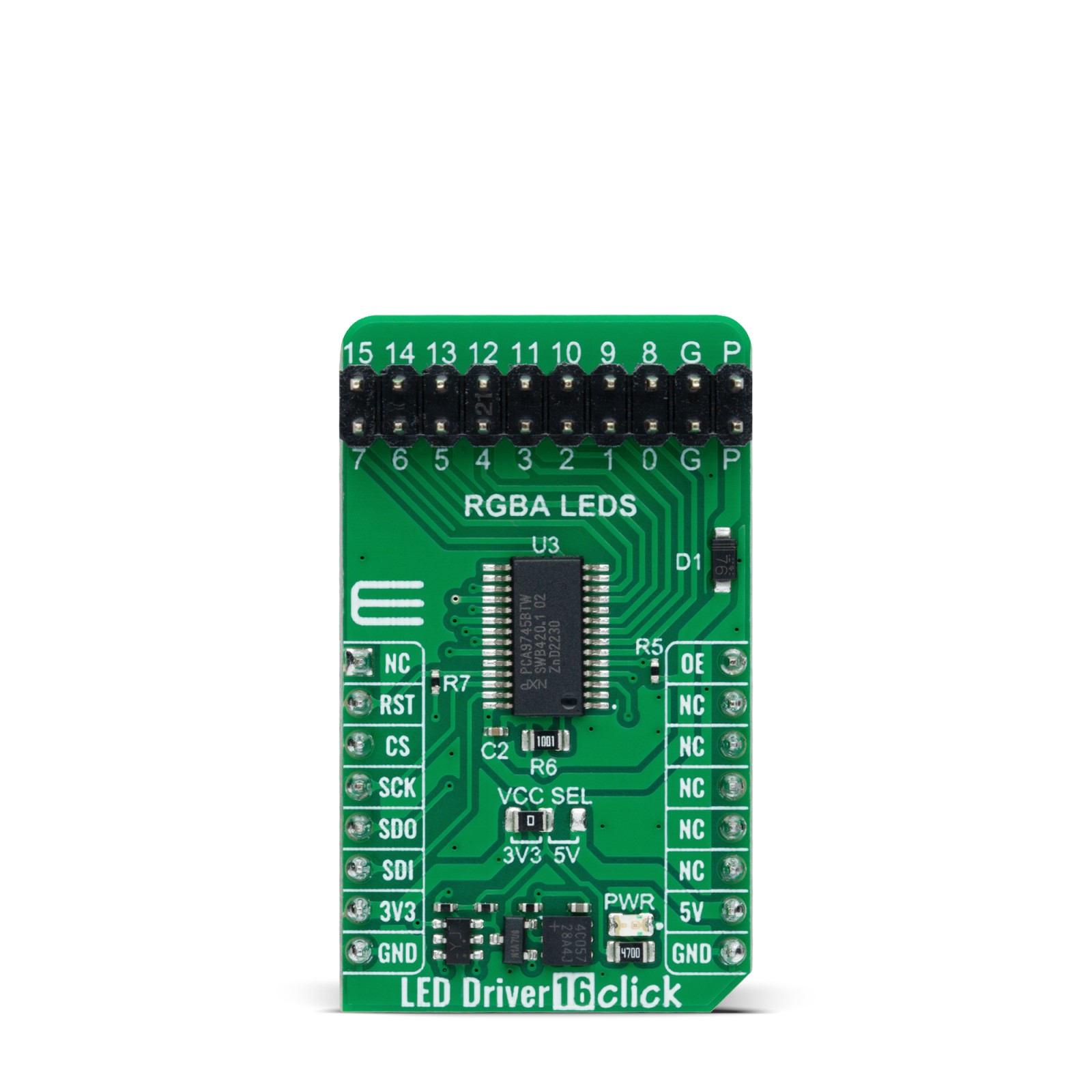
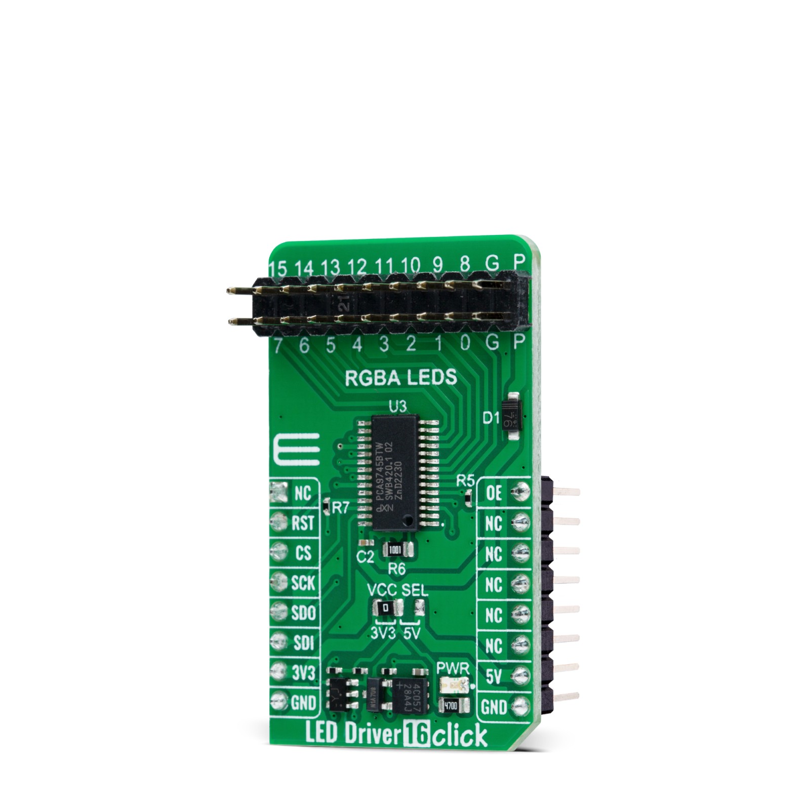
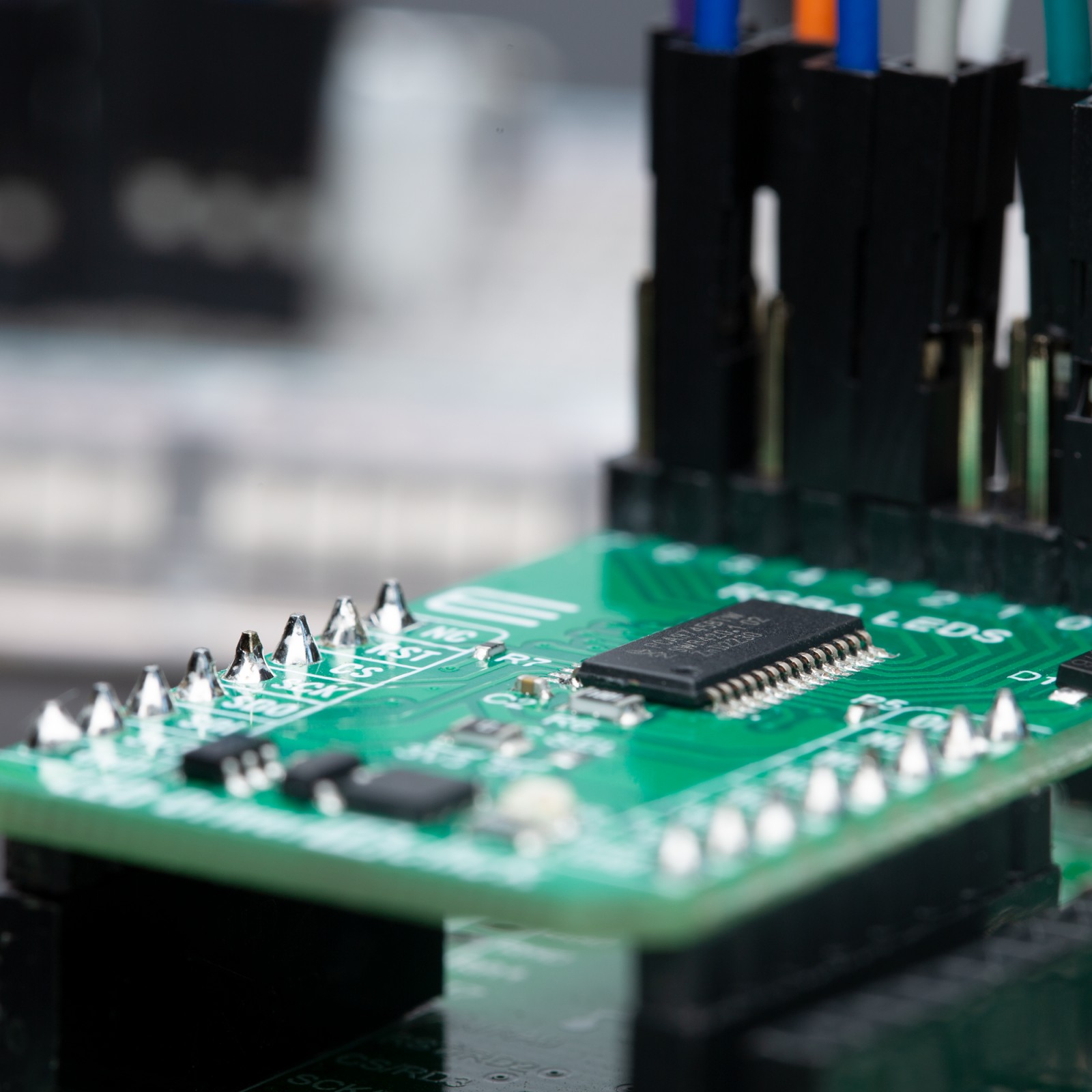
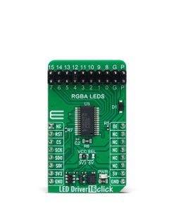
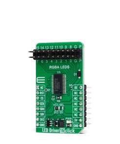
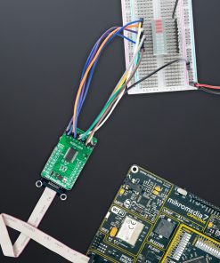
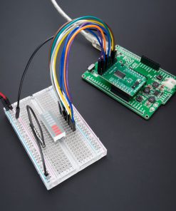
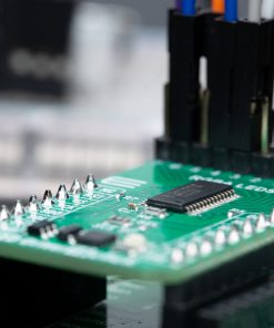
LED Driver 16 Click is based on the PCA9745B, a daisy-chain SPI-compatible 16-channel constant current LED driver from NXP Semiconductors. The PCA9745B provides a maximum output current of 57mA per channel (set through an onboard R6 resistor), making it suitable for dimming and blinking Red/Green/Blue/Amber (RGBA) LEDs. Each of the 16 LED outputs has its 8-bit resolution (256 steps) fixed-frequency individual PWM controller, operating at 31.25 kHz with an adjustable duty cycle. The duty cycle goes from 0% to 100%, allowing LEDs to be set to a specific brightness value; either dim or blink all LEDs with the same value.
Gradation control for all current sources is achieved through serial interface and 8-bit DACs, allowing users to ramp current automatically, without MCU intervention, and thus adjust brightness levels for each LED current source. There are four selectable gradation control groups, and each group has independently four registers to control ramp-up and ramp-down rate, step time, hold ON/OFF time, and final hold ON output current. Two gradation operation modes are available for each group: single shot mode (output pattern once) and continuous mode (output pattern repeat).
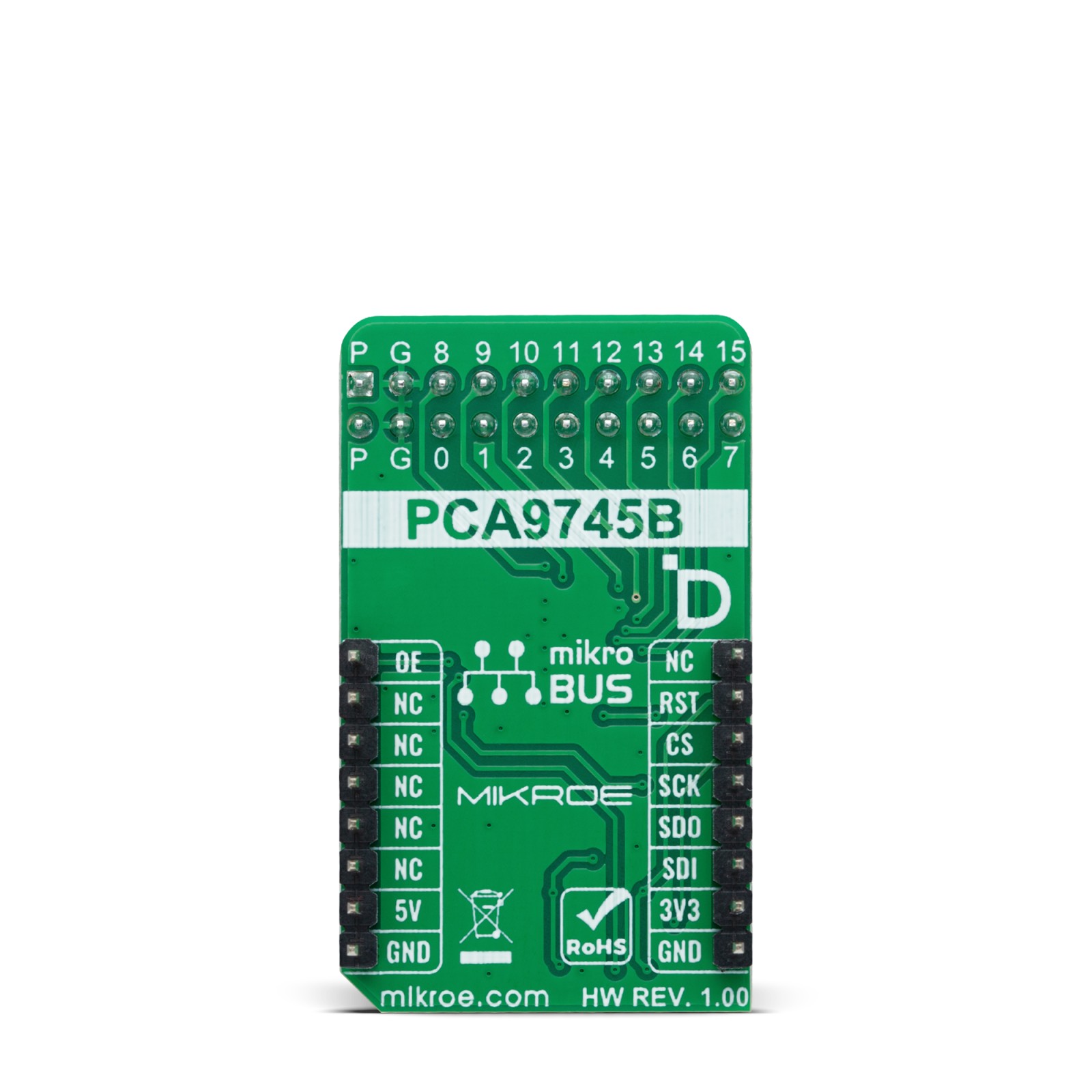
LED Driver 16 Click communicates with MCU through a register-selectable standard SPI interface that enables high clock speed up to 25MHz for optimum performance, supporting the most common SPI mode, SPI Mode 0. In addition to the SPI interface signals, this board uses several other signals from the mikroBUS™ socket. The reset pin routed on the RST pin of the mikroBUS™ socket provides the general reset ability, while the OE pin of the mikroBUS™ socket, hence, offers a switch operation (enabled/disabled) to turn ON/OFF power delivery to the PCA9745B. The OE pin can also be used as an external dimming control signal. In that case, the external clock frequency must be very high, more precisely unseen by the human eye, and the duty cycle value determines the brightness of the LEDs.
This Click board™ can operate with either 3.3V or 5V logic voltage levels selected via the VCC SEL jumper. This way, both 3.3V and 5V capable MCUs can use the communication lines properly. However, the Click board™ comes equipped with a library containing easy-to-use functions and an example code that can be used, as a reference, for further development.
Specifications
Type
LED Drivers
Applications
Can be used for dimming and blinking Red/Green/Blue/Amber (RGBA) LEDs for various consumer amusement applications, LED status signalization, and more
On-board modules
PCA9745B – 16-channel constant current LED driver from NXP Semiconductors
Key Features
Programmable outputs, gradation control for all channels, output channels can sink up to 57mA, output current adjustable through onboard resistor, protection features, SPI interface, output enable feature, and more
Interface
SPI
Feature
ClickID
Compatibility
mikroBUS™
Click board size
M (42.9 x 25.4 mm)
Input Voltage
3.3V or 5V
Pinout diagram
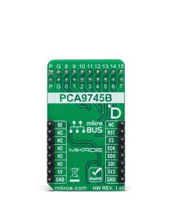
This table shows how the pinout on LED Driver 16 Click corresponds to the pinout on the mikroBUS™ socket (the latter shown in the two middle columns).
Onboard settings and indicators
Label | Name | Default | Description |
---|---|---|---|
LD1 | PWR | – | Power LED Indicator |
JP1 | VCC SEL | Left | Logic Level Voltage Selection 3V3/5V: Left position 3V3, Right position 5V |
J1 | – | Populated | LED Driver Channels Terminal |
LED Driver 16 Click electrical specifications
Description | Min | Typ | Max | Unit |
---|---|---|---|---|
Supply Voltage | 3.3 | – | 5 | V |
Output Current | – | – | 57 | mA |
Software Support
We provide a library for the LED Driver 16 Click as well as a demo application (example), developed using Mikroe compilers. The demo can run on all the main Mikroe development boards.
Package can be downloaded/installed directly from NECTO Studio Package Manager(recommended), downloaded from our LibStock™ or found on Mikroe github account.
Library Description
This library contains API for LED Driver 16 Click driver.
Key functions
-
leddriver16_set_led_state
This function sets the output state for the specified LEDs. -
leddriver16_set_led_pwm
This function sets the PWM duty cycle for the specified LEDs. -
leddriver16_set_led_iref
This function sets the gain settings for output current for the specified LEDs.
Example Description
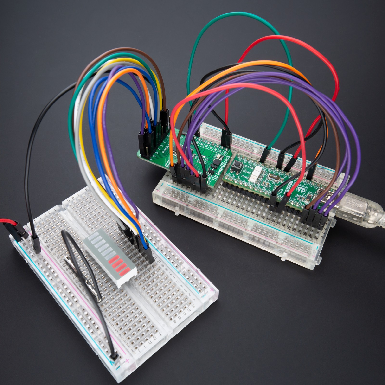
This example demonstrates the use of LED Driver 16 Click board™ by performing 3 different types of LED control (LED PWM dimming, LED blinking, and LED curtain).
void application_task ( void )
{
static uint8_t example_repeat_num = 5;
uint8_t repeat_cnt = 0;
log_printf( &logger, " LED PWM dimmingrnn" );
leddriver16_set_led_state ( &leddriver16, LEDDRIVER16_LED_CHANNEL_ALL, LEDDRIVER16_LEDOUT_PWM_ALL );
while ( repeat_cnt < example_repeat_num )
{
uint8_t pwm_duty = LEDDRIVER16_PWM_DUTY_MIN;
while ( pwm_duty < LEDDRIVER16_PWM_DUTY_MAX )
{
leddriver16_set_led_pwm ( &leddriver16, LEDDRIVER16_LED_CHANNEL_ALL, pwm_duty );
Delay_ms ( 5 );
pwm_duty++;
}
while ( pwm_duty > LEDDRIVER16_PWM_DUTY_MIN )
{
leddriver16_set_led_pwm ( &leddriver16, LEDDRIVER16_LED_CHANNEL_ALL, pwm_duty );
Delay_ms ( 5 );
pwm_duty--;
}
Delay_ms ( 100 );
repeat_cnt++;
}
log_printf( &logger, " LED blinkingrnn" );
repeat_cnt = 0;
leddriver16_set_led_state ( &leddriver16, LEDDRIVER16_LED_CHANNEL_ALL, LEDDRIVER16_LEDOUT_OFF );
while ( repeat_cnt < example_repeat_num )
{
leddriver16_set_led_state ( &leddriver16, LEDDRIVER16_LED_CHANNEL_ALL, LEDDRIVER16_LEDOUT_ON );
Delay_ms ( 500 );
leddriver16_set_led_state ( &leddriver16, LEDDRIVER16_LED_CHANNEL_ALL, LEDDRIVER16_LEDOUT_OFF );
Delay_ms ( 500 );
repeat_cnt++;
}
log_printf( &logger, " LED curtainrnn" );
repeat_cnt = 0;
leddriver16_set_led_state ( &leddriver16, LEDDRIVER16_LED_CHANNEL_ALL, LEDDRIVER16_LEDOUT_OFF );
while ( repeat_cnt < example_repeat_num )
{
uint8_t led_cnt = 0;
while ( led_cnt < 16 )
{
leddriver16_set_led_state ( &leddriver16, LEDDRIVER16_LED_CHANNEL_0 << led_cnt, LEDDRIVER16_LEDOUT_ON );
Delay_ms ( 100 );
leddriver16_set_led_state ( &leddriver16, LEDDRIVER16_LED_CHANNEL_0 << led_cnt, LEDDRIVER16_LEDOUT_OFF );
led_cnt++;
}
Delay_ms ( 500 );
repeat_cnt++;
}
}
The full application code, and ready to use projects can be installed directly from NECTO Studio Package Manager(recommended), downloaded from our LibStock™ or found on Mikroe github account.
Other Mikroe Libraries used in the example:
- MikroSDK.Board
- MikroSDK.Log
- Click.LEDDriver16
Additional notes and informations
Depending on the development board you are using, you may need USB UART click, USB UART 2 Click or RS232 Click to connect to your PC, for development systems with no UART to USB interface available on the board. UART terminal is available in all Mikroe compilers.
mikroSDK
This Click board™ is supported with mikroSDK – Mikroe Software Development Kit. To ensure proper operation of mikroSDK compliant Click board™ demo applications, mikroSDK should be downloaded from the LibStock and installed for the compiler you are using.
For more information about mikroSDK, visit the official page.