
ISO ADC Click
R470.00 ex. VAT
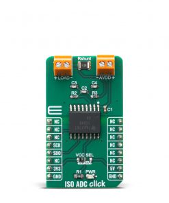
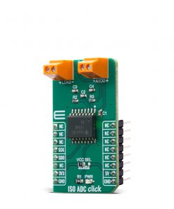
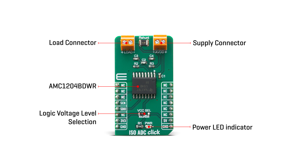
The ISO ADC Click is add-on board current-shunt measurement device with isolated delta-sigma modulator. This Click board™ is based on AMC1204BDWR provide a single-chip solution for measuring the small signal of a shunt resistor across an isolated barrier from Texas Instruments. ISO ADC Click contains shunt resistor, these types of resistors are typically used to sense currents in motor control inverters, green energy generation systems, and other industrial applications.
ISO ADC Click is supported by a mikroSDK compliant library, which includes functions that simplify software development. This Click board™ comes as a fully tested product, ready to be used on a system equipped with the mikroBUS™ socket.
Stock: Lead-time applicable.
| 5+ | R446.50 |
| 10+ | R423.00 |
| 15+ | R399.50 |
| 20+ | R384.46 |
How does it work?
The ISO ADC Click is current sensing system, which includes isolated delta-sigma modulator. The main IC on the ISO ADC click is AMC1204BDWR, from Texas Instruments.The current-sensing shunt resistor is designed as a 4 wire connected resistor that enables accurate measurements through a force-sense connection. The AMC1204BDWR differential inputs easily connect to the shunt resistor, An internal reference eliminates the need for external components.
The Click board™ communicates with the target microcontroller over SPI interface on the mikroBUS™ line. The analog input range is tailored to directly accommodate the voltage drop across a shunt resistor used for current sensing. The SiO2 -based capacitive isolation barrier supports a high level of magnetic field immunity as described in the Digital Isolator Magnetic-Field Immunity application report. The external clock input simplifies the synchronization of multiple current sense channels on system level. The extended frequency range of up to 20 MHz and is provided externally at the CLKIN pin. The data are synchronously provided at 20 MHz at the DATA output pin. The data are changing at the falling edge of CLKIN.
The ISO ADC Click perform current measurement on LOAD connector, the AMC1204BDWR measure the differential input signal VIN = (VINP – VINN) on two ends of the shunt resistor,against the internal reference of 2.5 V using internal capacitors that are continuously charged and discharged.The current measurement can’t be possible without external power supply on AVDD connector.
The voltage level of the logic section can be selected via VCC SEL jumper, between 3.3V and 5V. This allows for both 3.3V and 5V capable MCUs to use the SPI communication lines properly.
Specifications
Type
ADC,Isolators
Applications
ISO ADC click can be used to sense currents in motor control inverters, green energy generation systems, and other industrial applications.
On-board modules
AMC1204BDWR, Isolated Delta-Sigma Modulator for Current-Shunt Measurement, from Texas Instruments.
Key Features
±250-mV input voltage range optimized for shunt resistors, High electromagnetic field immunity, External clock input for easier synchronization
Interface
SPI
Feature
No ClickID
Compatibility
mikroBUS™
Click board size
M (42.9 x 25.4 mm)
Input Voltage
3.3V or 5V
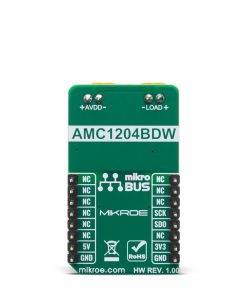
Pinout diagram
This table shows how the pinout on ISO ADC Click corresponds to the pinout on the mikroBUS™ socket (the latter shown in the two middle columns).
| Notes | Pin | Pin | Notes | ||||
|---|---|---|---|---|---|---|---|
| NC | 1 | AN | PWM | 16 | NC | ||
| NC | 2 | RST | INT | 15 | NC | ||
| NC | 3 | CS | RX | 14 | NC | ||
| SPI Clock | SCK | 4 | SCK | TX | 13 | NC | |
| SPI Data OUT | SDO | 5 | MISO | SCL | 12 | NC | |
| 6 | MOSI | SDA | 11 | NC | |||
| Power Supply | 3.3V | 7 | 3.3V | 5V | 10 | 5V | Power Supply |
| Ground | GND | 8 | GND | GND | 9 | GND | Ground |
Onboard settings and indicators
| Label | Name | Default | Description |
|---|---|---|---|
| LD1 | PWR | – | Power LED Indicator |
| JP1 | VCC SEL | Left | Logic voltage level selection: left position 3.3V, right position 5V |
ISO ADC Click electrical specifications
| Description | Min | Typ | Max | Unit |
|---|---|---|---|---|
| Voltage supply (AVDD) | 4.5 | 5 | 5.5 | V |
| Current (LOAD) | – | – | 3 | A |
| CLKIN | 0 | – | 20 | MHz |
Software Support
We provide a library for the ISO ADC Click as well as a demo application (example), developed using MIKROE compilers. The demo can run on all the main MIKROE development boards.
Package can be downloaded/installed directly from NECTO Studio Package Manager (recommended), downloaded from our LibStock™ or found on MIKROE github account.
Library Description
This library contains API for ISO ADC Click driver.
Key functions
-
isoadc_read_voltageThis function reads a raw ADC in ISOADC_ADC_NUM_AVERAGES number of samples and converts it to a shunt voltage in millivolts. -
isoadc_get_currentThis function converts a shunt voltage input to a load current in milliampers. -
isoadc_get_powerThis function converts a shunt voltage input to electrical power in watts.
Example Description
This example demonstrates the use of ISO ADC Click by reading the shunt voltage, current, and power.
void application_task ( void )
 {
     float voltage = 0;
     float avg_voltage = 0;
     uint16_t avg_cnt = 0;

     log_printf( &logger, " --- MEASUREMENT IN PROGRESS ---rn" );
     log_info( &logger, "Keep the load and power supply stable during the measurement processrn" );

     while ( avg_cnt < ISOADC_VOLTAGE_NUM_AVERAGES )
     {
         if ( ISOADC_OK == isoadc_read_voltage ( &isoadc, &voltage ) )
         {
             avg_voltage += voltage;
             avg_cnt++;
         }
     }
     voltage = avg_voltage / ISOADC_VOLTAGE_NUM_AVERAGES;
     log_printf( &logger, " Shunt Voltage: %.1f mVrn", voltage );
     log_printf( &logger, " Current: %.3f mArn", isoadc_get_current ( voltage ) );
     log_printf( &logger, " Power: %.3f Wrn", isoadc_get_power ( &isoadc, voltage ) );
     log_printf( &logger, "-------------------------rnn" );
     Delay_ms ( 1000 );
 }
The full application code, and ready to use projects can be installed directly from NECTO Studio Package Manager (recommended), downloaded from our LibStock™ or found on MIKROE github account.
Other MIKROE Libraries used in the example:
- MikroSDK.Board
- MikroSDK.Log
- Click.ISOADC
Additional notes and informations
Depending on the development board you are using, you may need USB UART click, USB UART 2 Click or RS232 Click to connect to your PC, for development systems with no UART to USB interface available on the board. UART terminal is available in all MIKROE compilers.
mikroSDK
This Click board™ is supported with mikroSDK – MIKROE Software Development Kit. To ensure proper operation of mikroSDK compliant Click board™ demo applications, mikroSDK should be downloaded from the LibStock and installed for the compiler you are using.
For more information about mikroSDK, visit the official page.
Resources
Downloads
| Weight | 23 g |
|---|---|
| Brand | MikroElektronika |