How does it work?
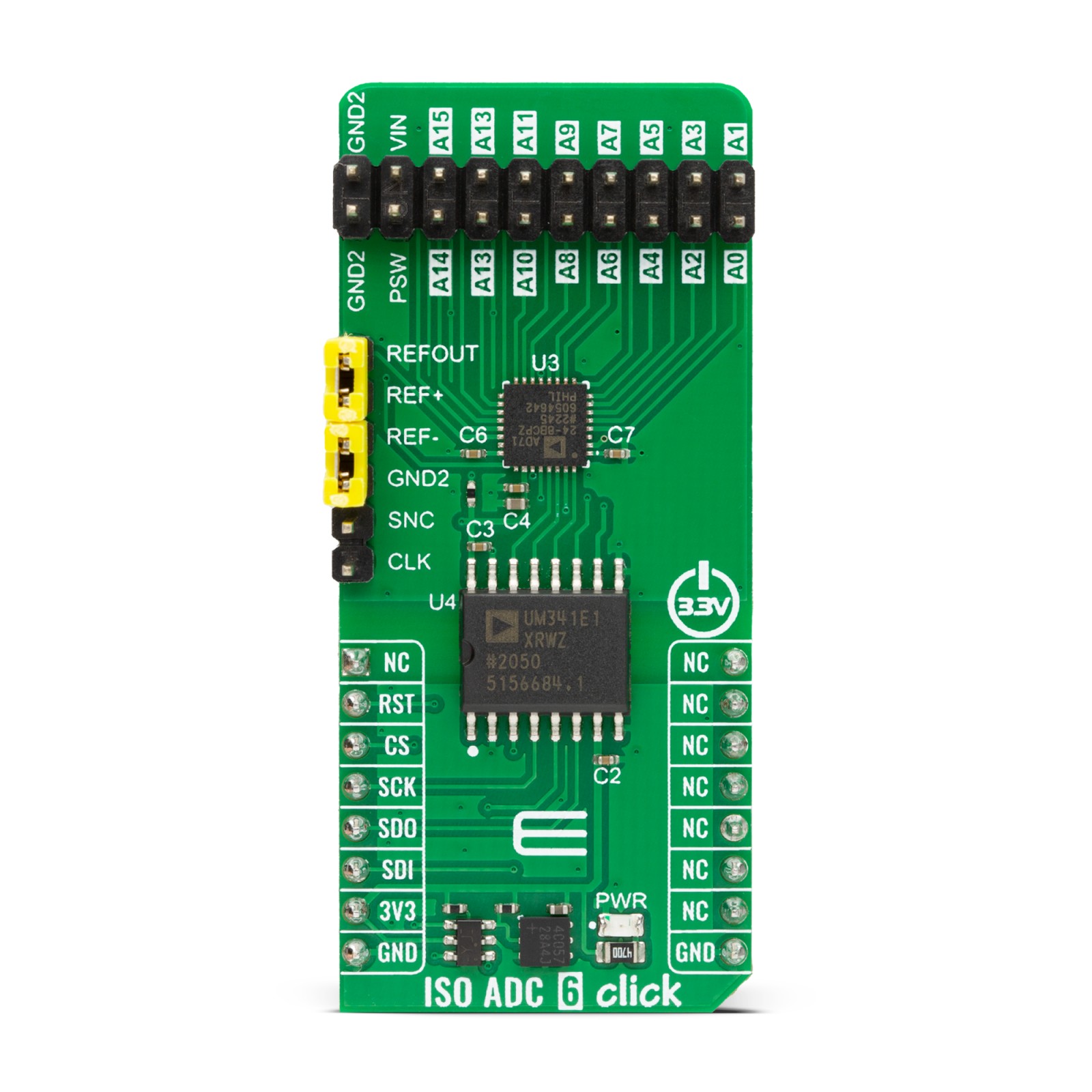
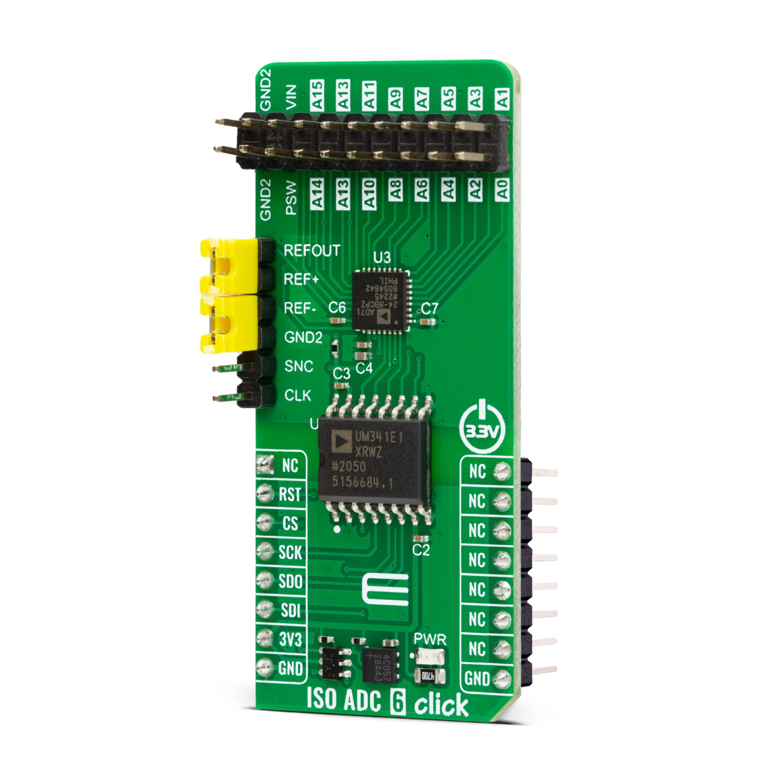
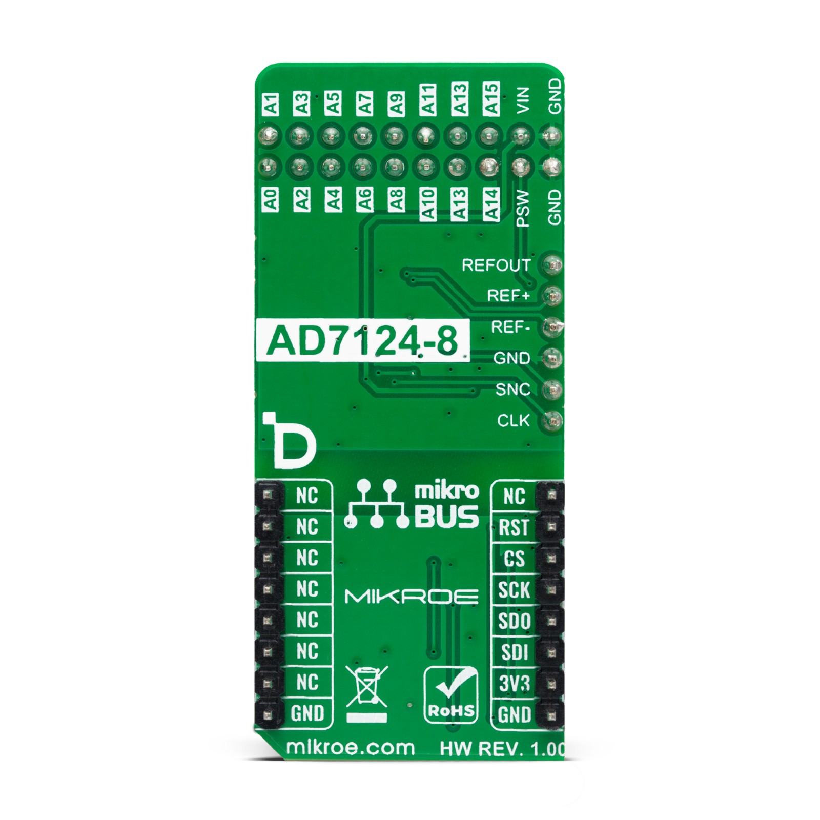
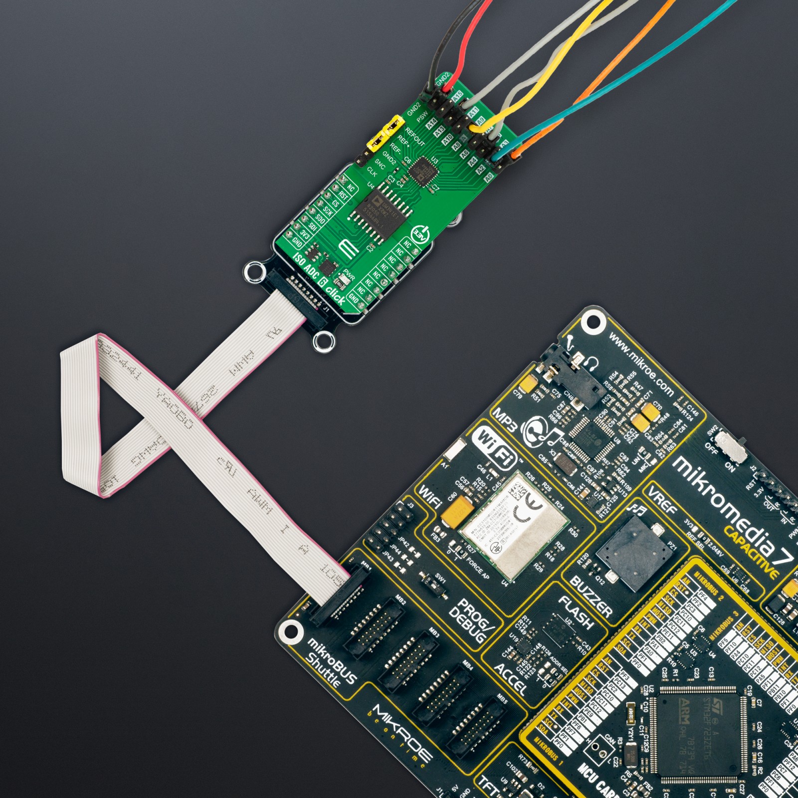
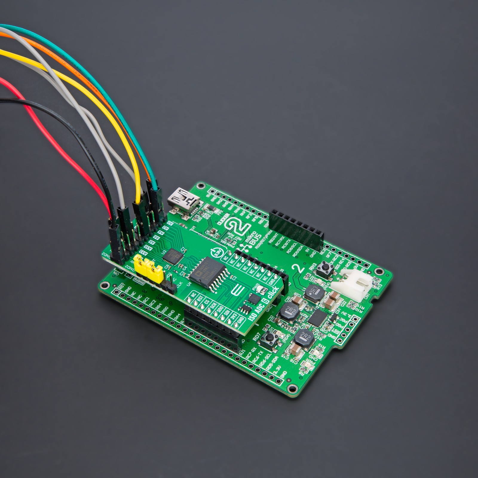
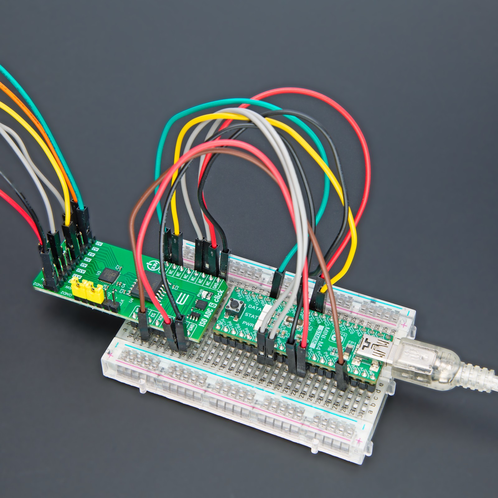
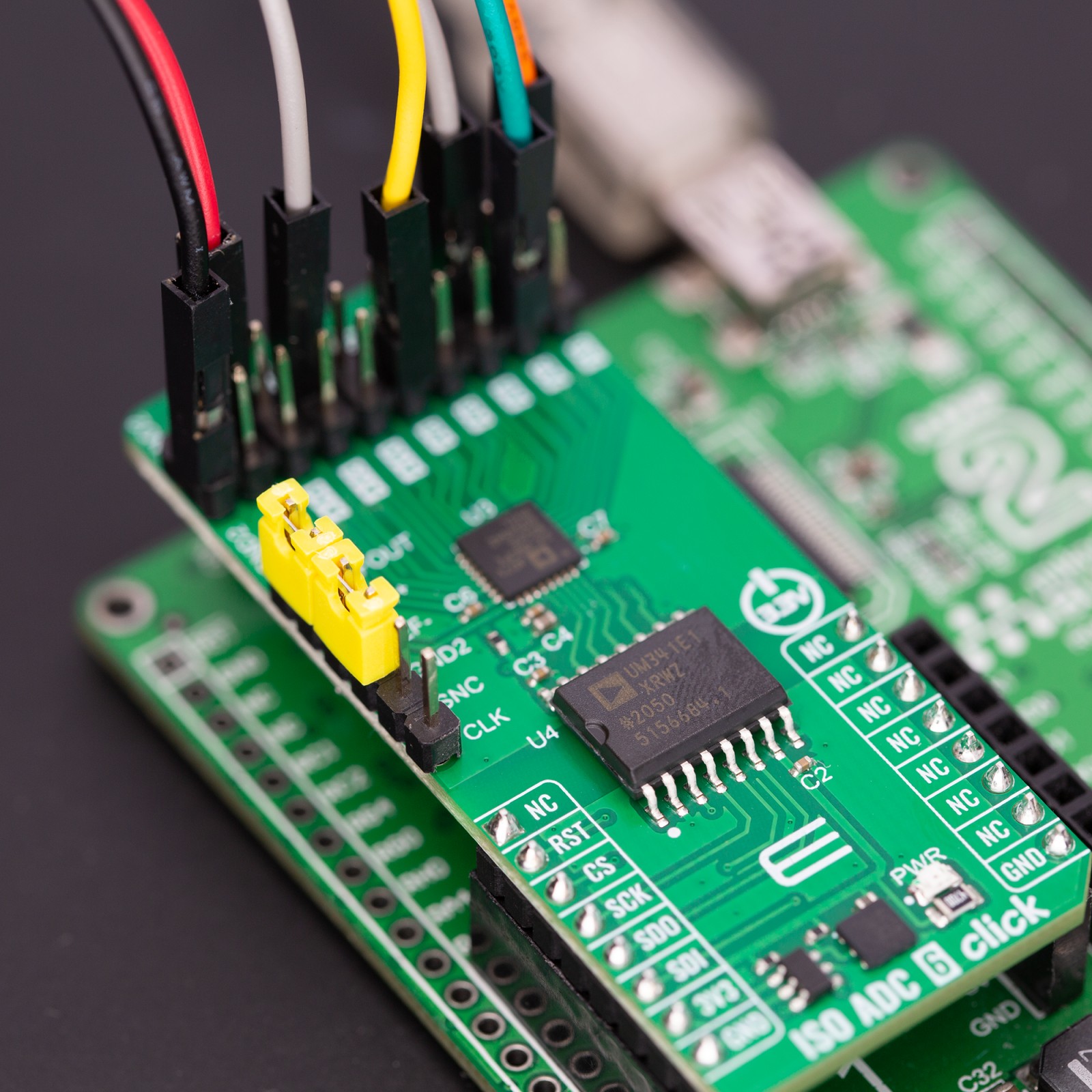
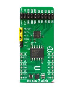
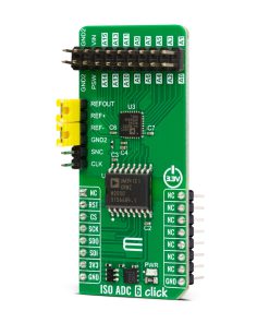
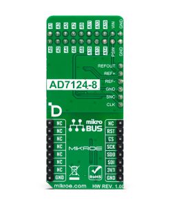
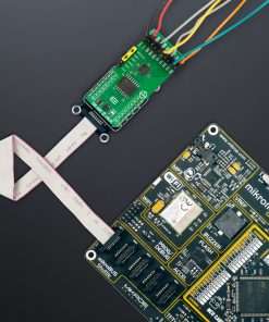
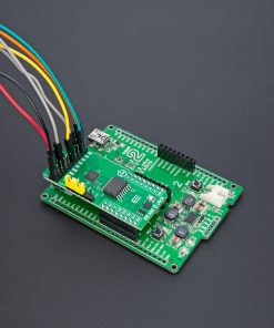
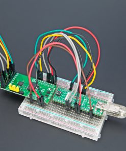
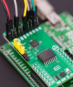
ISO ADC 6 Click is based on the AD7124-8, an 8-channel, low noise, low power, 24-bit, sigma-delta ADC, and the ADuM341E, a 5kVrms quad digital isolator, both from Analog Devices. The ADC incorporates a sigma-delta modulator, buffer, reference, gain stage, and on-chip digital filtering. It is intended to measure wide dynamic ranges, weigh scales, temperature measurement applications, and low-frequency signals. The ADC allows up to 16 configurations or channels consisting of analog inputs, reference inputs, or power supplies. All ADC channels are available over the A0-15 header, with a common GND, power supply, and a bridge power switch (PSW).
You can add an external reference over the REF+ and REF- pins. The internal reference has its output available over the REFOUT pin. The synchronization input is also available over the SNC pin. It allows synchronization of the digital filters and analog modulators when using several AD7124-8 devices. For this purpose, the internal clock is available over the CLK pin. Alternatively, the internal clock can be turned off, and this pin can provide an external clock, allowing simultaneous conversions.
The isolator isolates the ADC communication lines to the host MCU. It features low propagation delay, low dynamic power consumption, 100Mbps maximum guaranteed data rate, and more. The isolator is based on CMOS, a monolithic air core transformer technology, and iCoupler technology.
ISO ADC 6 Click uses a standard 4-wire SPI serial interface of the ADC to communicate with the host MCU over the isolator barrier. The isolator uses a high-frequency carrier to transmit data across the isolation barrier using iCoupler chip scale transformer coils separated by layers of polyimide isolation. The ADC can work in three power modes, which allows sampling in a range of 1.17sps up to 19200sps.
This Click board™ can be operated only with a 3.3V logic voltage level. The board must perform appropriate logic voltage level conversion before using MCUs with different logic levels. Also, it comes equipped with a library containing functions and an example code that can be used as a reference for further development.
Specifications
Type
ADC
Applications
Can be used for the development of a wide variety of industrial measurements, data acquisition systems, monitoring functions, and more
On-board modules
AD7124-8 – 24-bit sigma-delta ADC from Analog Devices
ADuM341E – 5kVrms quad digital isolator from Analog Devices
Key Features
Full SPI serial interface isolation, 8 ADC channels, wide output data rate, low RMS noise, three power modes, rail-to-rail analog inputs, diagnostic functions, crosspoint multiplexed analog inputs, 8 differential/15 pseudo differential inputs, programmable gain, and more
Interface
SPI
Feature
ClickID
Compatibility
mikroBUS™
Click board size
L (57.15 x 25.4 mm)
Input Voltage
3.3V,External
Pinout diagram
This table shows how the pinout on ISO ADC 6 Click corresponds to the pinout on the mikroBUS™ socket (the latter shown in the two middle columns).
Onboard settings and indicators
Label | Name | Default | Description |
---|---|---|---|
LD1 | PWR | – | Power LED Indicator |
ISO ADC 6 Click electrical specifications
Description | Min | Typ | Max | Unit |
---|---|---|---|---|
Supply Voltage | – | 3.3 | – | V |
External Supply Voltage | – | 3.3 | – | V |
Output Data Rate | 1.17 | – | 19200 | sps |
Programmable Gain | 1 | – | 128 | – |
UL Recognition (for 1 min) | – | – | 5 | kVrms |
Software Support
We provide a library for the ISO ADC 6 Click as well as a demo application (example), developed using MIKROE compilers. The demo can run on all the main MIKROE development boards.
Package can be downloaded/installed directly from NECTO Studio Package Manager (recommended), downloaded from our LibStock™ or found on Mikroe github account.
Library Description
This library contains API for ISO ADC 6 Click driver.
Key functions
-
isoadc6_get_voltage
ISO ADC 6 get voltage level function. -
isoadc6_get_adc_data
ISO ADC 6 get ADC data function. -
isoadc6_set_adc_control
ISO ADC 6 set ADC control function.
Example Description
This example demonstrates the use of the ISO ADC 6 Click board™ by reading and writing data by using SPI serial interface and reading results of AD conversion.
void application_task ( void )
{
float voltage = 0;
if ( ISOADC6_OK == isoadc6_get_voltage( &isoadc6, &voltage ) )
{
log_printf( &logger, " Voltage: %.3f [V]rn", voltage );
Delay_ms( 1000 );
}
}
The full application code, and ready to use projects can be installed directly from NECTO Studio Package Manager (recommended), downloaded from our LibStock™ or found on Mikroe github account.
Other Mikroe Libraries used in the example:
- MikroSDK.Board
- MikroSDK.Log
- Click.ISOADC6
Additional notes and informations
Depending on the development board you are using, you may need USB UART click, USB UART 2 Click or RS232 Click to connect to your PC, for development systems with no UART to USB interface available on the board. UART terminal is available in all MIKROE compilers.
mikroSDK
This Click board™ is supported with mikroSDK – MIKROE Software Development Kit. To ensure proper operation of mikroSDK compliant Click board™ demo applications, mikroSDK should be downloaded from the LibStock and installed for the compiler you are using.
For more information about mikroSDK, visit the official page.