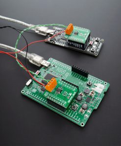
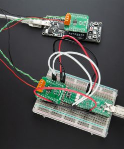
How does it work?
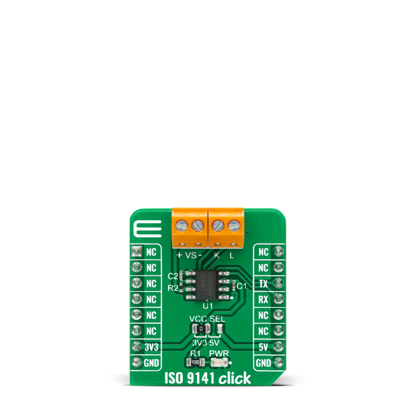
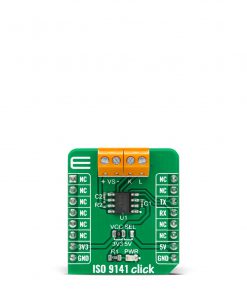
ISO 9141 Click is based on the L9637, a monolithic bus driver designed to provide bidirectional serial communication in automotive diagnostic applications according to the specification “Diagnostic Systems ISO9141” from ST Microelectronics. The L9637 is also known as the K-Line Transceiver that provides a bidirectional link, called K, and a separate comparator, called L, to the related diagnosis bus that can be connected on terminal labeled with K and L on this Click board™. The K and L pins are protected against overvoltages and reverse battery condition. During the lack of power supply or ground, all pins show high impedance characteristics.
The L9637 has a wide supply voltage in a range from 4.5V to 36V, as well as several modes of operation like Standby Mode with low current consumption and overtemperature Shut-Down Mode. The overtemperature Shut-Down Mode switches OFF the K output if the L9637’s temperature increases above the thermal shut down threshold. To reactivate K again the temperature must decrease below the K switch ON temperature value. To achieve no fault for power supply under-voltage conditions the outputs will be switched OFF and stay at high impedance.
ISO 9141 Click communicates with MCU using the UART interface with the default baud rate of 9600bps, and commonly used UART RX and TX pins for the data transfer. The UART input TX and output RX of K are associated with the logic voltage level from mikroBUS™ (VCC) with its integrated pull-up resistances. Also, the L comparator output pin named LO has a pull-up resistance connected to VCC. All bus defined inputs L and K have supply voltage-dependent thresholds together with sufficient hysteresis to suppress line spikes.
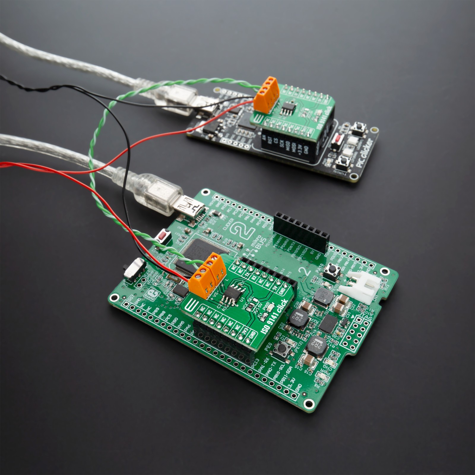
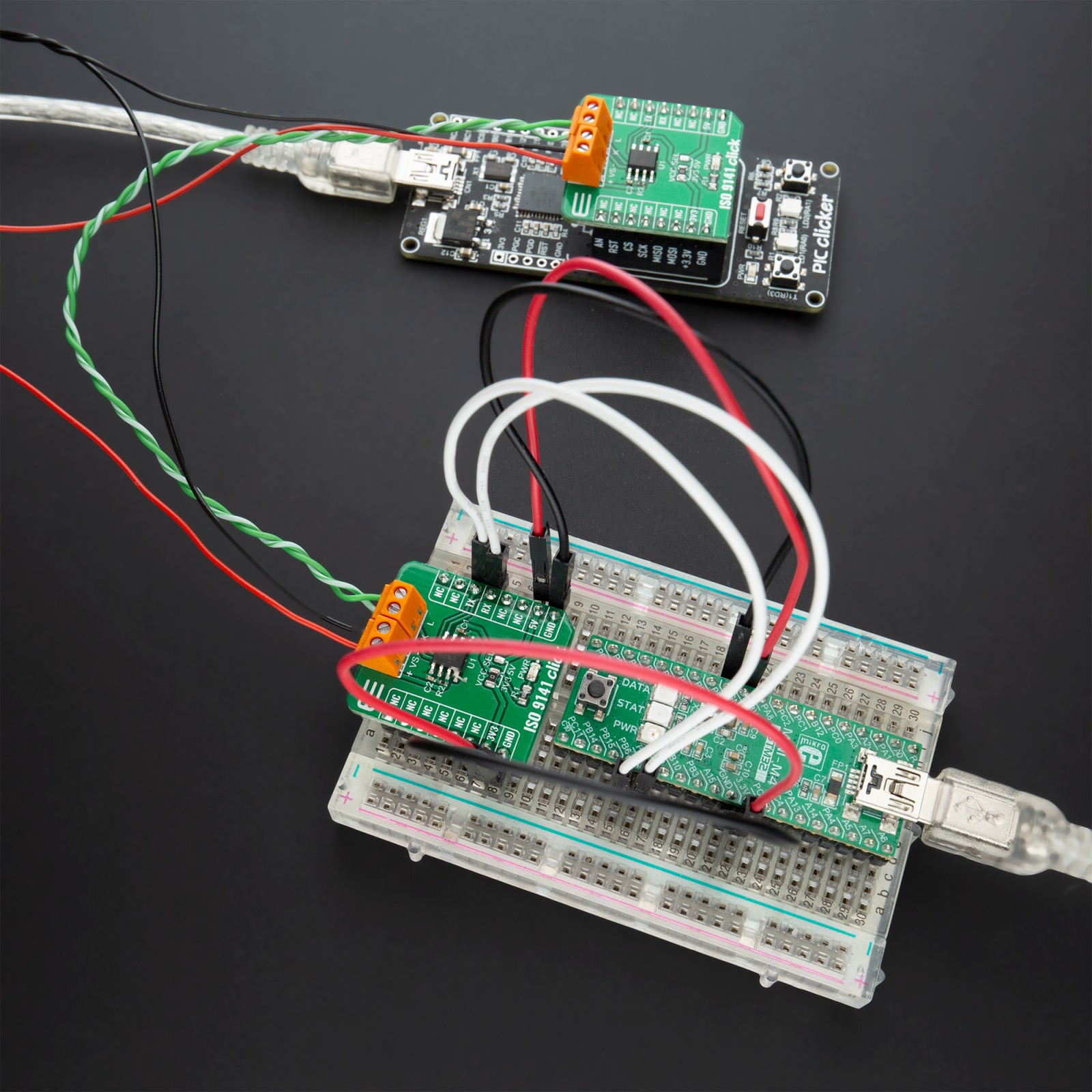
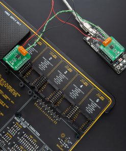
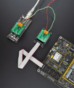
This Click board™ is easy to program because it does not require an overly demanding configuration. Only what is necessary for the errorless work is the selection of the appropriate mode of operation, whether the Click board™ will work as a receiver or transmitter. In this way, the transmitter will send the data every 2 seconds while the receiving side will receive the data in a „byte-by-byte“ format. This can also be seen in an example code that contains easy to use functions that may be used as a reference for further development.
This Click board™ is designed to be operated with both 3.3V and 5V logic voltage levels that can be selected via VCC SEL jumper. This allows for both 3.3V and 5V capable MCUs to use the UART communication lines properly. However, the Click board™ comes equipped with a library that contains easy to use functions and an example code that can be used as a reference for further development.
Specifications
Type
CAN
Applications
Can be used for automotive diagnostic applications such as powertrain for ICE (CNG/LPG engine control or diesel/gasoline injection), an automotive gateway in telematics and networking, and many more.
On-board modules
ISO 9141 Click is based on the L9637, a monolithic bus driver designed to provide bidirectional serial communication in automotive diagnostic applications according to the specification “Diagnostic Systems ISO9141” from ST Microelectronics.
Key Features
Wide input and output voltage range, overtemperature shut down function, bidirectional K I/O pin with supply voltage dependent input threshold, Stand-by Mode with very low current consumption, and more.
Interface
UART
Feature
No ClickID
Compatibility
mikroBUS™
Click board size
S (28.6 x 25.4 mm)
Input Voltage
3.3V or 5V
Pinout diagram
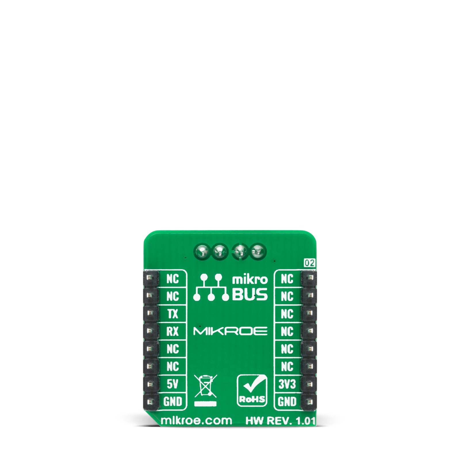
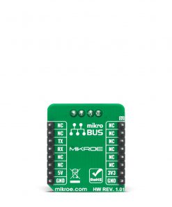
This table shows how the pinout on ISO 9141 Click corresponds to the pinout on the mikroBUS™ socket (the latter shown in the two middle columns).
Onboard settings and indicators
Label | Name | Default | Description |
---|---|---|---|
LD1 | PWR | – | Power LED Indicator |
JP1 | VCC SEL | Left | Power Supply Voltage Selection 3V3/5V: Left position 3V3, Right position 5V |
ISO 9141 Click electrical specifications
Description | Min | Typ | Max | Unit |
---|---|---|---|---|
Supply Voltage | 4.5 | – | 36 | V |
K output current | – | 60 | – | mA |
Transmission frequency | – | – | 50 | kHz |
Operating Temperature Range | -40 | – | +150 | °C |
Software Support
We provide a library for the ISO9141 Click on our LibStock page, as well as a demo application (example), developed using MikroElektronika compilers. The demo can run on all the main MikroElektronika development boards.
Library Description
The library covers all the necessary functions to control ISO 9141 click board. Library performs a standard UART interface communication.
Key functions:
void iso9141_write_byte ( uint8_t input )
– Write Single Byte.uint8_t iso9141_read_byte ( void )
– Read Single Byte.uint8_t iso9141_byte_ready ( void )
– Check for new byte received.
Examples description
The application is composed of three sections :
- System Initialization – Initializes UART used for communication and another UART bus used for data logging.
- Application Initialization – Initializes UART driver. In addition to this module is placed inside transmitter working mode cappable of transmission of the data.
- Application Task – (code snippet) – This is an example that demonstrates the use of ISO 9141 Click board. Transmitter/Receiver task depend on uncommented code Receiver logging each received byte to the UART for data logging, while transmitted send messages every 2 seconds.
void application_task ( ) { char tmp; uint8_t drdy_flag; if ( app_mode == APP_MODE_RECEIVER ) { // RECEIVER - UART polling drdy_flag = iso9141_byte_ready( ); if ( 1 == drdy_flag ) { tmp = iso9141_read_byte( ); mikrobus_logWrite( &tmp, _LOG_BYTE ); } } else { // TRANSMITER - TX each 2 sec for ( tmp = 0; tmp < 9; tmp++ ) { iso9141_write_byte( demo_message_data[ tmp ] ); Delay_ms( 10 ); } mikrobus_logWrite( " Message Sent! ", _LOG_LINE ); mikrobus_logWrite( "-------------------", _LOG_LINE ); Delay_ms( 2000 ); } }
The full application code, and ready to use projects can be found on our LibStock page.
Other mikroE Libraries used in the example:
- UART
Additional notes and informations
Depending on the development board you are using, you may need USB UART click, USB UART 2 click or RS232 click to connect to your PC, for development systems with no UART to USB interface available on the board. The terminal available in all MikroElektronika compilers, or any other terminal application of your choice, can be used to read the message.
mikroSDK
This Click board™ is supported with mikroSDK – MikroElektronika Software Development Kit. To ensure proper operation of mikroSDK compliant Click board™ demo applications, mikroSDK should be downloaded from the LibStock and installed for the compiler you are using.
For more information about mikroSDK, visit the official page.