How does it work?
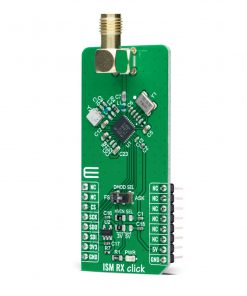
ISM RX Click as its foundation uses the MAX1471, a low-power CMOS superheterodyne receiver for both ASK and FSK data without reconfiguration from Analog Devices. It includes all the active components such as a low-noise amplifier, an image-reject mixer, a fully integrated PLL, 10.7MHz IF limiting amplifier received-signal strength indicator, low-noise FM demodulator, and a 3V voltage regulator. The MAX1471 can achieve data rates as high as 33kbps using Manchester Code (66kbps nonreturn to zero) depending on signal power and component selection.
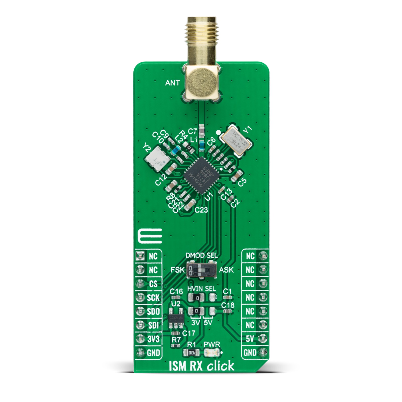
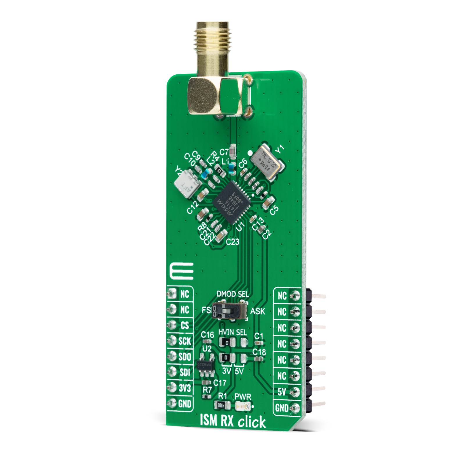
As already mentioned before, this Click board™ can receive both ASK and FSK data simultaneously. This feature of the MAX1471 can be achieved and selected with the switch labeled as DMOD SEL that allows the selection between ASK and FSK data. The MAX1471 receives binary FSK or ASK data on a frequency of 433.92MHz, which is set based on the used components. ASK modulation uses a difference in the carrier’s amplitude to represent logic 0 and logic 1 data, while the FSK uses the difference in frequency of the carrier.
Differential peak-detecting data demodulators are available for both the FSK and ASK analog baseband data recovery. The MAX1471 consists of a discontinuous Receive mode for low-power operation, configured through a serial interface. This mode also allows self-polling, where the MAX1471 can stay in Sleep mode as long as eight minutes and wake the system MCU, offering additional power savings. On the consumption side, it draws less than 1.1µA in Shutdown and only 7mA in Receive mode.
ISM RX Click communicates with MCU using a standard SPI interface and possesses the SMA antenna connector with an impedance of 50Ω. This Click board™ can use it to connect the appropriate antenna that Mikroe has in its offer, such as Rubber Antenna 433MHz Straight, for improved range and received signal strength.
This Click board™ operates only with a 5V logic voltage level from the mikroBUS™ socket. Still, the MAX1471 power supply offers the possibility of using both 3V, obtained by the NCP170 voltage regulator, and 5V logic voltage level selected via the HVIN SEL jumpers. Note that all the jumpers must be placed to the same side, or else the Click board™ may become unresponsive. However, the Click board™ comes equipped with a library containing easy-to-use functions and an example code that can be used, as a reference, for further development.
Specifications
Type
Sub-1 GHz Transceievers
Applications
Can be used for remote low-speed communication, such as remote keyless access, garage or gate doors control, industrial control, home automation, and similar applications where this kind of communication is applicable
On-board modules
MAX1471 – low-power CMOS superheterodyne receiver for both ASK and FSK data without reconfiguration from Maxim Integrated
Key Features
Low power consumption, ASK and FSK demodulated data selection, programmable through serial user interface, low current consumption, and more.
Interface
SPI
Feature
No ClickID
Compatibility
mikroBUS™
Click board size
L (57.15 x 25.4 mm)
Input Voltage
3.3V or 5V
Pinout diagram
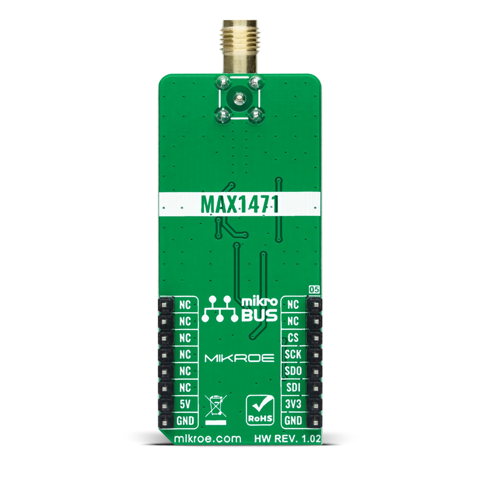
This table shows how the pinout on ISM RX Click corresponds to the pinout on the mikroBUS™ socket (the latter shown in the two middle columns).
Onboard settings and indicators
Label | Name | Default | Description |
---|---|---|---|
LD1 | PWR | – | Power LED Indicator |
JP1-JP2 | HVIN SEL | Left | Logic Level Voltage Selection 3V/5V: Left position 3V, Right position 5V |
SW1 | DMOD SEL | Left | FSK/ASK Data Output Selection |
ISM RX Click electrical specifications
Description | Min | Typ | Max | Unit |
---|---|---|---|---|
Supply Voltage | 3 | – | 5 | V |
ISM RX Frequency Range | – | 433.92 | – | MHz |
RX Mode Current | – | 7 | – | mA |
Sensitivity (ASK/FSK) | – | -114/-108 | – | dBm |
Operating Temperature Range | -40 | +25 | +125 | °C |
Software Support
We provide a library for the ISM RX Click as well as a demo application (example), developed using MikroElektronika compilers. The demo can run on all the main MikroElektronika development boards.
Package can be downloaded/installed directly from NECTO Studio Package Manager(recommended way), downloaded from our LibStock™ or found on mikroE github account.
Library Description
This library contains API for ISM RX Click driver.
Key functions:
ismrx_cfg_setup
– Config Object Initialization function.ismrx_init
– Initialization function.ismrx_default_cfg
– Click Default Configuration function.
Examples description
This application shows capability of ISM RX Click board. It sets default configuration, and collects and processes data from signal that received from ISM TX Click board. It can collect and process data from 2 type of the signal modulation( FSK and ASK ).
void application_task ( void ) { if ( ismrx_get_data( &ismrx ) ) { buffer[ buffer_cnt ] = '1'; } else { buffer[ buffer_cnt ] = '0'; } buffer_cnt++; //Delay for sample ratio to be effective Delay_us( 60 ); if ( buffer_cnt > BUFFER_SIZE ) { proces_samples(); clear_buffers(); } }
The full application code, and ready to use projects can be installed directly from NECTO Studio Package Manager(recommended way), downloaded from our LibStock™ or found on mikroE github account.
Other mikroE Libraries used in the example:
- MikroSDK.Board
- MikroSDK.Log
- Click.ISMRX
Additional notes and informations
Depending on the development board you are using, you may need USB UART click, USB UART 2 click or RS232 click to connect to your PC, for development systems with no UART to USB interface available on the board. The terminal available in all MikroElektronika compilers, or any other terminal application of your choice, can be used to read the message.
mikroSDK
This Click board™ is supported with mikroSDK – MikroElektronika Software Development Kit. To ensure proper operation of mikroSDK compliant Click board™ demo applications, mikroSDK should be downloaded from the LibStock and installed for the compiler you are using.
For more information about mikroSDK, visit the official page.