How does it work?
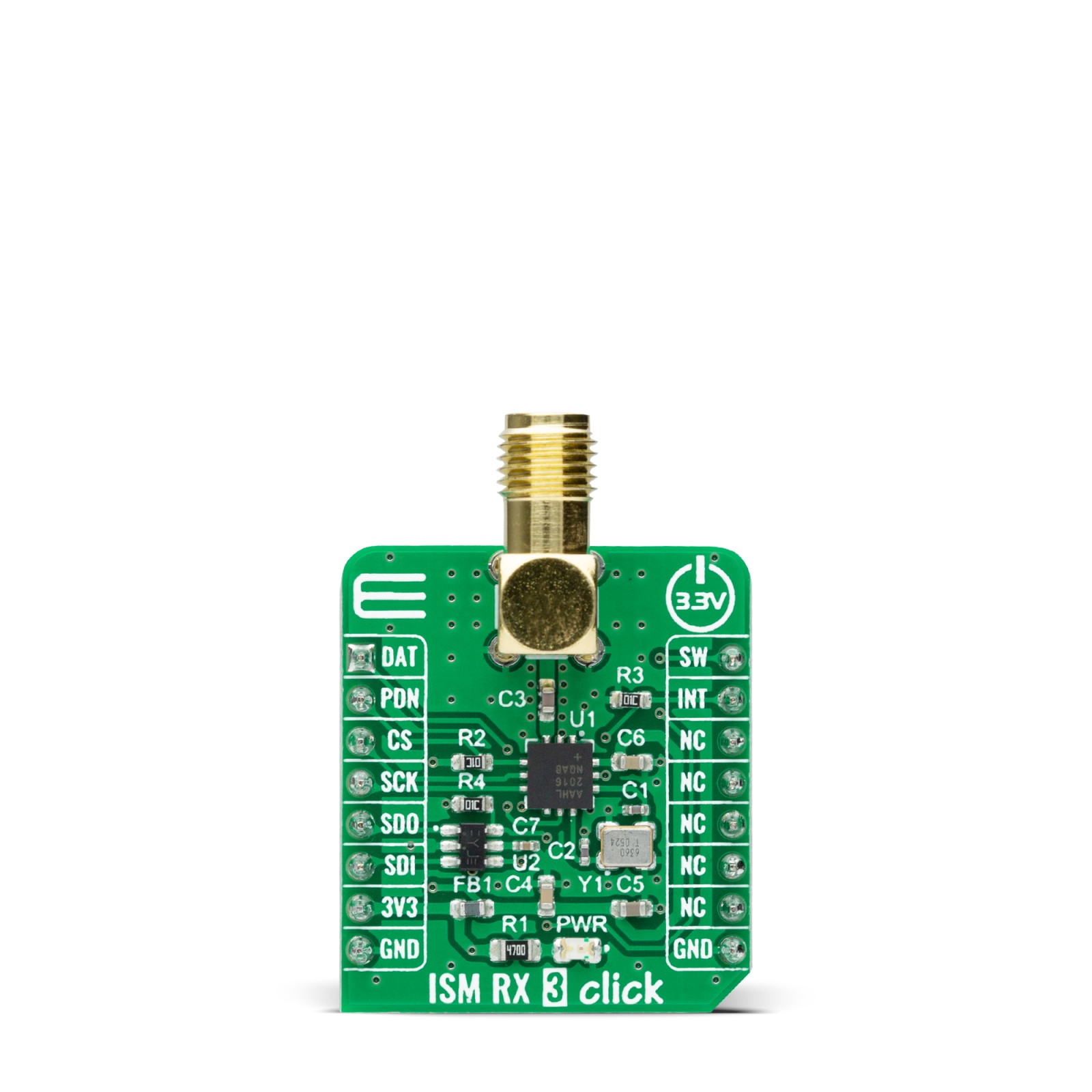
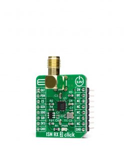
ISM RX 3 Click as its foundation uses the MAX41470, a sub-GHz ISM RF receiver from Analog Devices. This IC is designed to receive ASK/OOK or FSK/GFSK modulated data in the 287MHz to 320MHz (nominally 315MHz), 425MHz to 480MHz (nominally 434MHz), and 860MHz to 960MHz (nominally 868MHz or 915MHz) ISM frequency bands, using an onboard 16MHz crystal. This Click board™ comes with an ASK modulation and 433.92MHz with a 5bps data rate as its default configuration. Its additional features also include automatic gain control (AGC), a received signal strength indicator (RSSI), automatic frequency control (AFC), and a frequency error indicator (FEI).
The MAX41470 has four power states: Shutdown, Sleep, Standby, and Receive-Active. Its Power-Down pin, labeled as PDN and routed to the RST pin of the mikroBUS™ socket, optimizes power consumption used for power ON/OFF purposes. When the device is enabled (the PDN pin set to a low logic state), the device operational states are controlled through the serial interface by the internal registers.
This Click board™ communicates with MCU through a standard SPI interface that enables very high clock speeds up to 20MHz, supporting the most common SPI mode, SPI Mode 3 to program the internal registers for complete control of the MAX41470. When in programming mode, the MAX41470 can support a self-polling operation to provide an interrupt signal on the DAT pin routed to the AN pin of the mikroBUS™ socket.
The MAX41470 comes only with one data pin for register programming, both data input/output pin. For that purpose, this Click board™ uses the 74LVC1G3157 multiplexer to avoid conflict with other functions driven by the same pin, enabling both writing and reading via the SPI interface and using the 4-wire SPI interface. The selection of the multiplexer channel, more precisely the MISO or MOSI line, is chosen by a logic level on the S line of the multiplexer, set by an SW pin routed to the PWM pin of the mikroBUS™ socket.
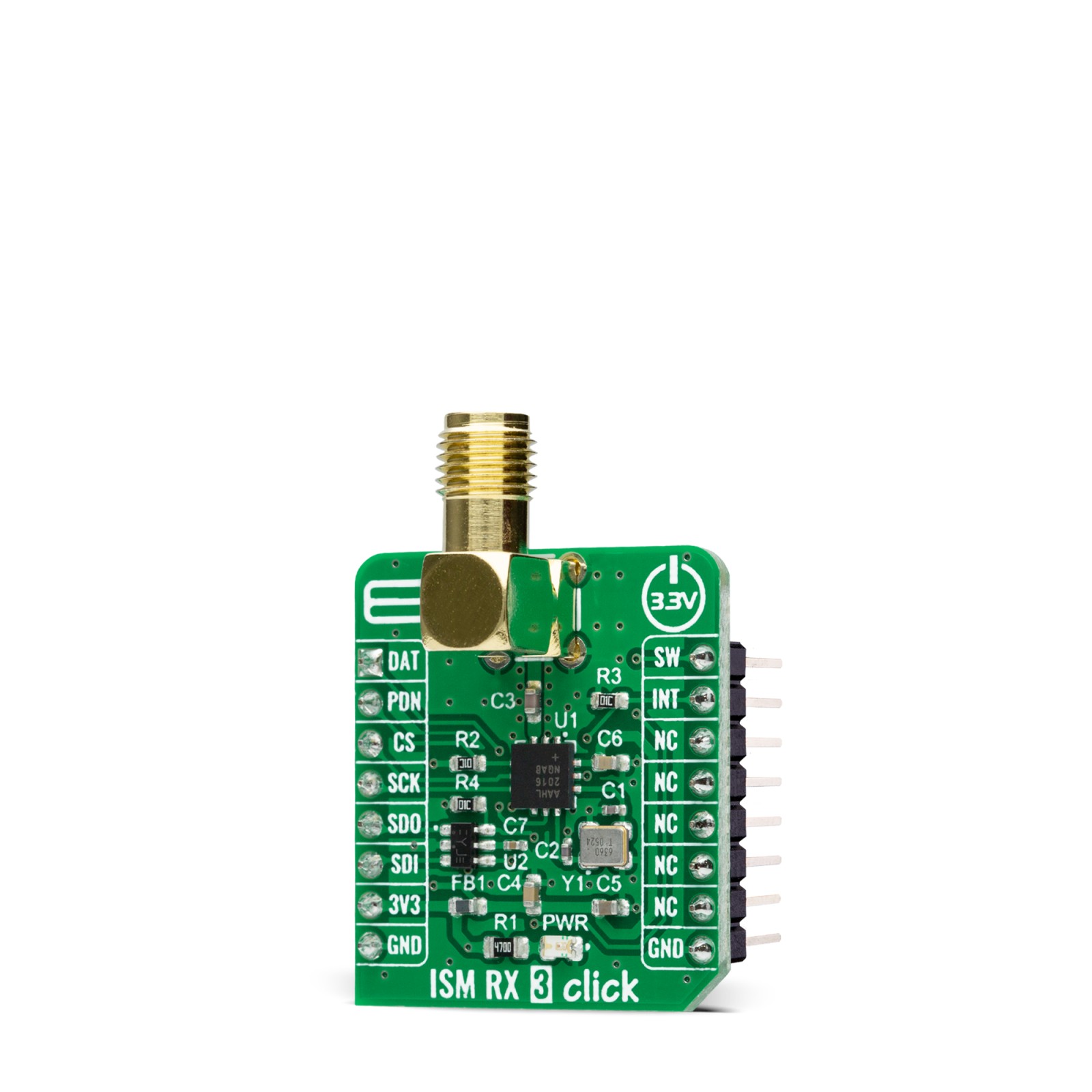
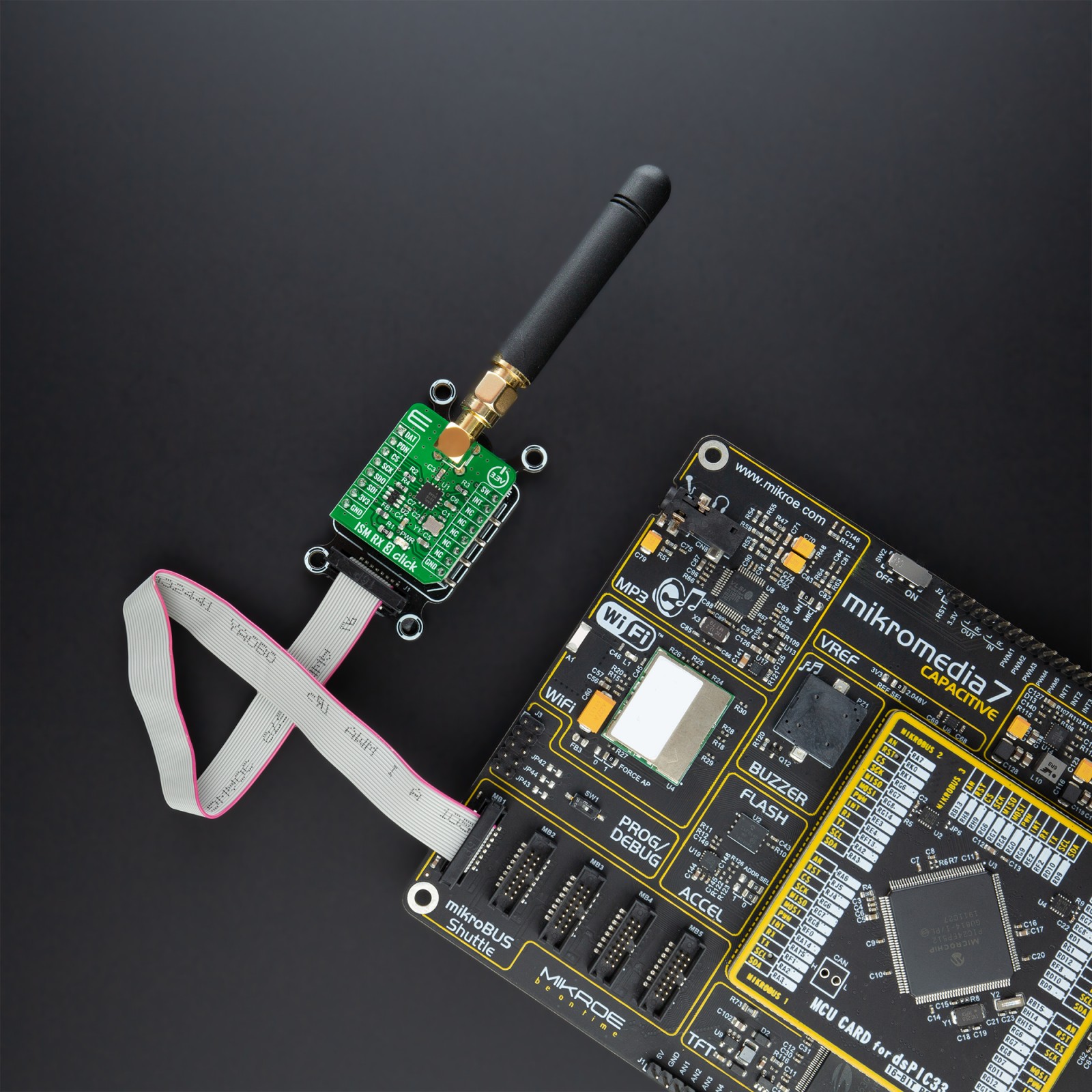
ISM RX 3 Click possesses the SMA antenna connector with an impedance of 50Ω, which can use it to connect the appropriate antenna that Mikroe has in its offer for improved range and received signal strength.
This Click board™ can be operated only with a 3.3V logic voltage level. The board must perform appropriate logic voltage level conversion before use with MCUs with different logic levels. However, the Click board™ comes equipped with a library containing functions and an example code that can be used, as a reference, for further development.
Specifications
Type
Sub-1 GHz Transceievers
Applications
Can be used for home automation and security, building access control, remote keyless entry, garage or gate doors control, and similar applications
On-board modules
MAX41470 – sub-GHz ISM RF receiver from Maxim Integrated, now part of Analog Devices
Key Features
Long range with high sensitivity, low power consumption, high performance, self-polling (remote wake-up) for reduced power, gain and frequency control, and more
Interface
SPI
Feature
No ClickID
Compatibility
mikroBUS™
Click board size
S (28.6 x 25.4 mm)
Input Voltage
3.3V
Pinout diagram
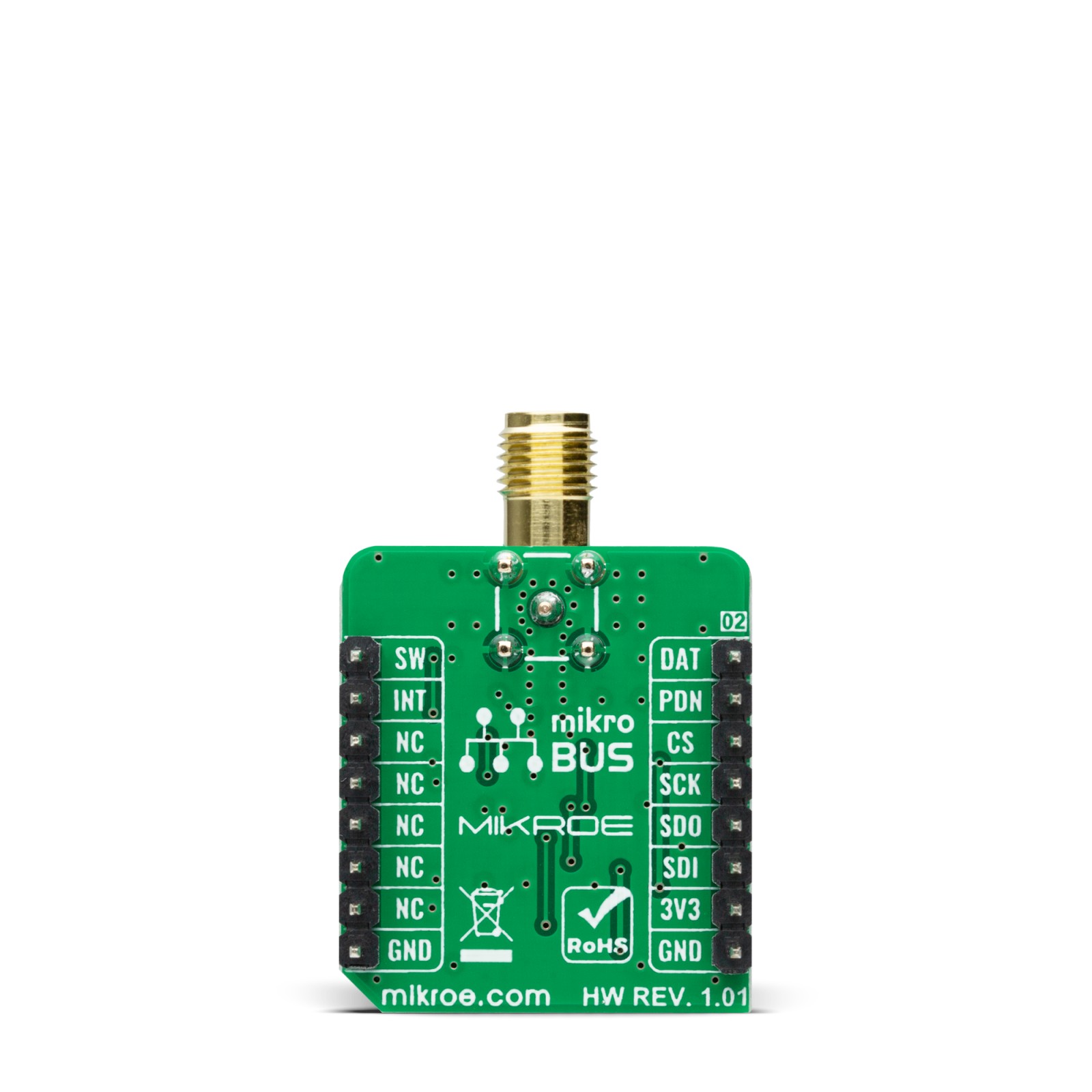
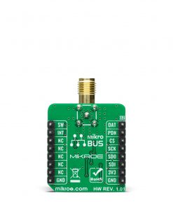
This table shows how the pinout on ISM RX 3 Click corresponds to the pinout on the mikroBUS™ socket (the latter shown in the two middle columns).
Onboard settings and indicators
Label | Name | Default | Description |
---|---|---|---|
LD1 | PWR | – | Power LED Indicator |
ISM RX 3 Click electrical specifications
Description | Min | Typ | Max | Unit |
---|---|---|---|---|
Supply Voltage | – | 3.3 | – | V |
Frequency Range | 287 | – | 320 | MHz |
425 | – | 480 | ||
860 | – | 960 | ||
Data Rate | – | 200 | – | kbps |
Sensitivity | – | -127 | – | dBm |
Operating Temperature Range | -40 | +25 | +105 | °C |
Software Support
We provide a library for the ISM RX 3 Click as well as a demo application (example), developed using MikroElektronika compilers. The demo can run on all the main MikroElektronika development boards.
Package can be downloaded/installed directly from NECTO Studio Package Manager(recommended way), downloaded from our LibStock™ or found on mikroE github account.
Library Description
This library contains API for ISM RX 3 Click driver.
Key functions:
ismrx3_reset
– Reset function.ismrx3_get_data
– Read data output.ismrx3_get_clk
– Read clock output.
Examples description
This example showcases ability of click board to configure and read incoming rf signal and parses data using data and clock line.
void application_task ( void ) { if ( ismrx3_get_clk( &ismrx3 ) ) { sample = ismrx3_get_data( &ismrx3 ); if ( last_sample == sample ) { consecutive++; } else { if ( consecutive < 4 ) { manchester_buf[ manchester_counter++ ] = last_sample + 48; } else if ( consecutive < 6 ) { manchester_buf[ manchester_counter++ ] = last_sample + 48; manchester_buf[ manchester_counter++ ] = last_sample + 48; } consecutive = 1; last_sample = sample; } while ( ismrx3_get_clk( &ismrx3 ) ); } if ( manchester_counter >= MANCHESTER_BUF_LEN - 1 ) { parse_samples( ); manchester_counter = 0; } }
The full application code, and ready to use projects can be installed directly from NECTO Studio Package Manager(recommended way), downloaded from our LibStock™ or found on mikroE github account.
Other mikroE Libraries used in the example:
- MikroSDK.Board
- MikroSDK.Log
- Click.ISMRX3
Additional notes and informations
Depending on the development board you are using, you may need USB UART click, USB UART 2 click or RS232 click to connect to your PC, for development systems with no UART to USB interface available on the board. The terminal available in all MikroElektronika compilers, or any other terminal application of your choice, can be used to read the message.
mikroSDK
This Click board™ is supported with mikroSDK – MikroElektronika Software Development Kit. To ensure proper operation of mikroSDK compliant Click board™ demo applications, mikroSDK should be downloaded from the LibStock and installed for the compiler you are using.
For more information about mikroSDK, visit the official page.