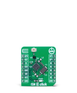
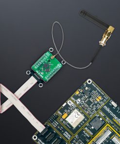
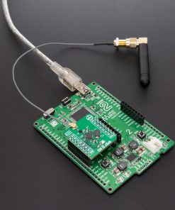
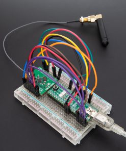
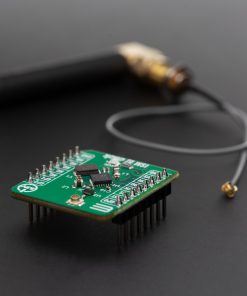
ISM 3 Click is a compact add-on board designed for low-power wireless communication in the sub-1 GHz ISM and SRD frequency bands. This board features the S2-LP 433MHz RF transceiver from STMicroelectronics, known for its high performance and ultra-low power consumption. The S2-LP supports multiple modulation schemes with programmable data rates, offers excellent receiver sensitivity, adjustable RF output power, features such as automatic packet handling and support for SIGFOX™ and MONARCH networks. Communication with the host MCU is established via a 4-wire SPI interface, and additional flexibility is provided through three configurable GPIO pins. Ideal for a wide range of applications, ISM 3 Click is perfect for smart metering, home automation, industrial monitoring, wireless alarms, and other sensor-to-cloud solutions.
ISM 3 Click is fully compatible with the mikroBUS™ socket and can be used on any host system supporting the mikroBUS™ standard. It comes with the mikroSDK open-source libraries, offering unparalleled flexibility for evaluation and customization. What sets this Click board™ apart is the groundbreaking ClickID feature, enabling your host system to seamlessly and automatically detect and identify this add-on board.
 WiFi Plus Click
1 × R2,200.00
WiFi Plus Click
1 × R2,200.00  Expand 18 Click
1 × R275.00
Expand 18 Click
1 × R275.00  RN4678 Click
1 × R840.00
RN4678 Click
1 × R840.00  Charger 28 Click
1 × R530.00
Charger 28 Click
1 × R530.00  Ambient 21 Click
1 × R255.00
Ambient 21 Click
1 × R255.00 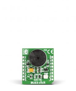 BUZZ Click
1 × R115.00
BUZZ Click
1 × R115.00