How does it work?
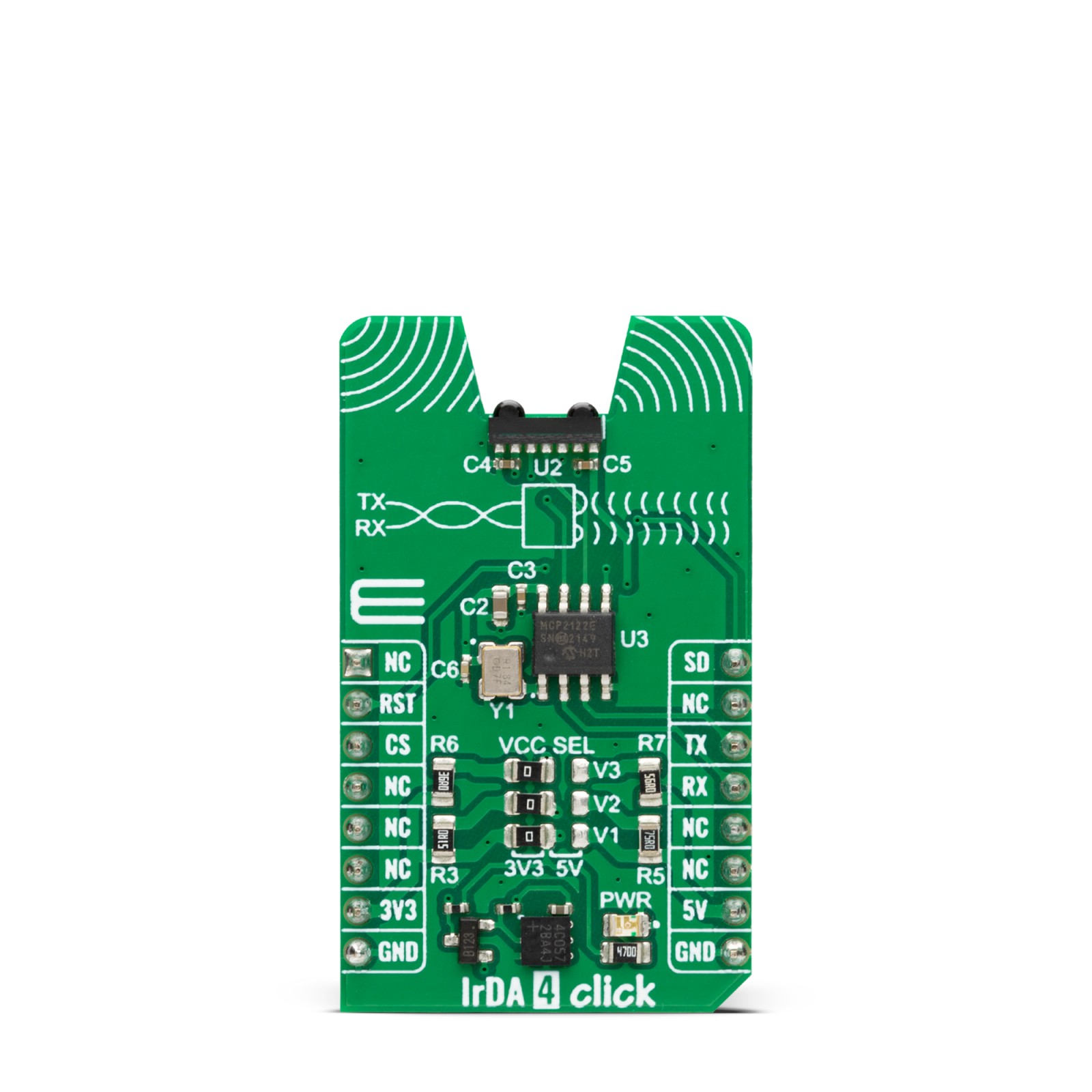
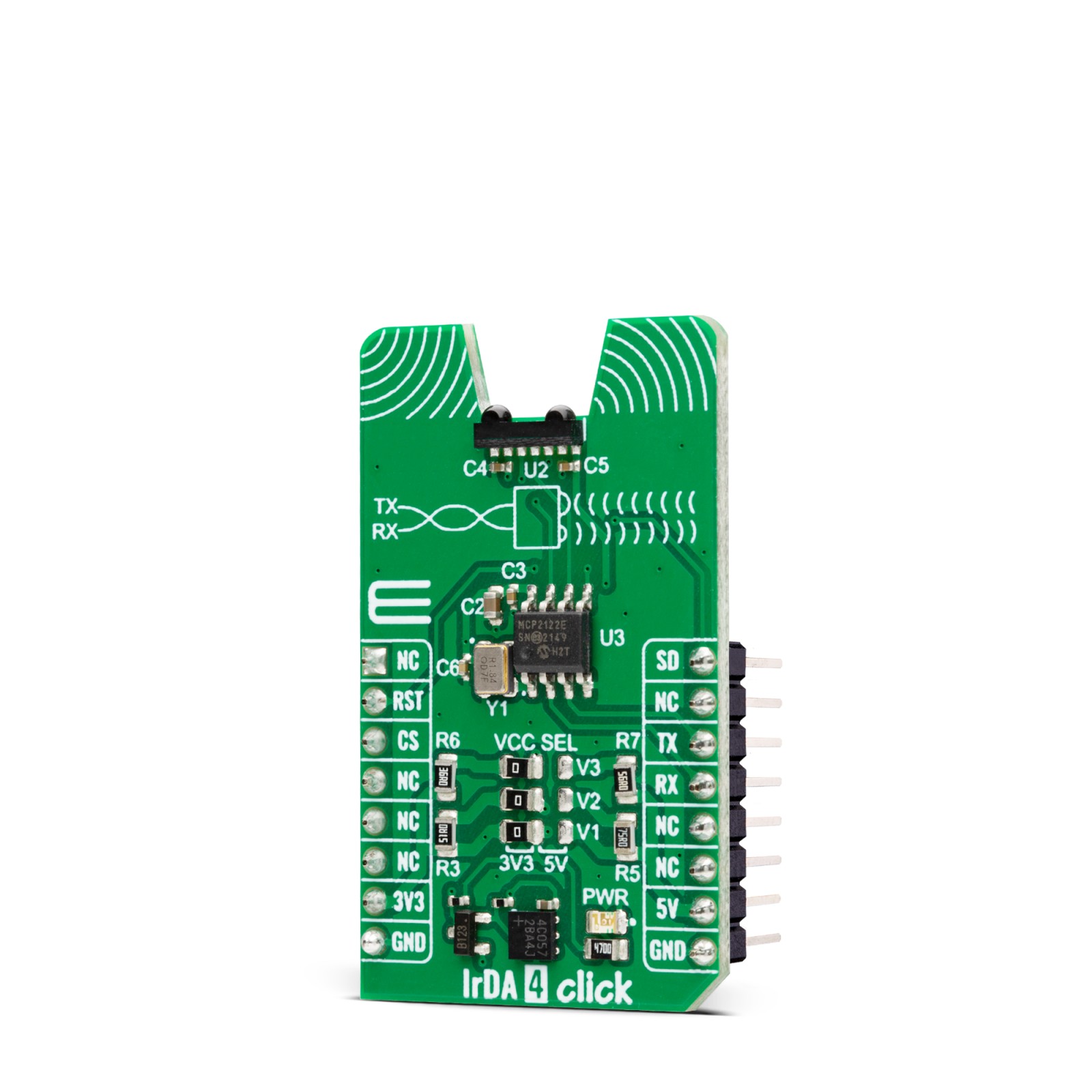
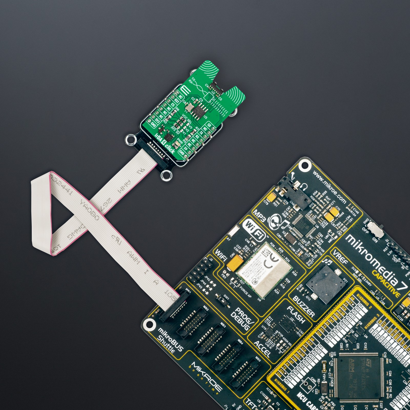
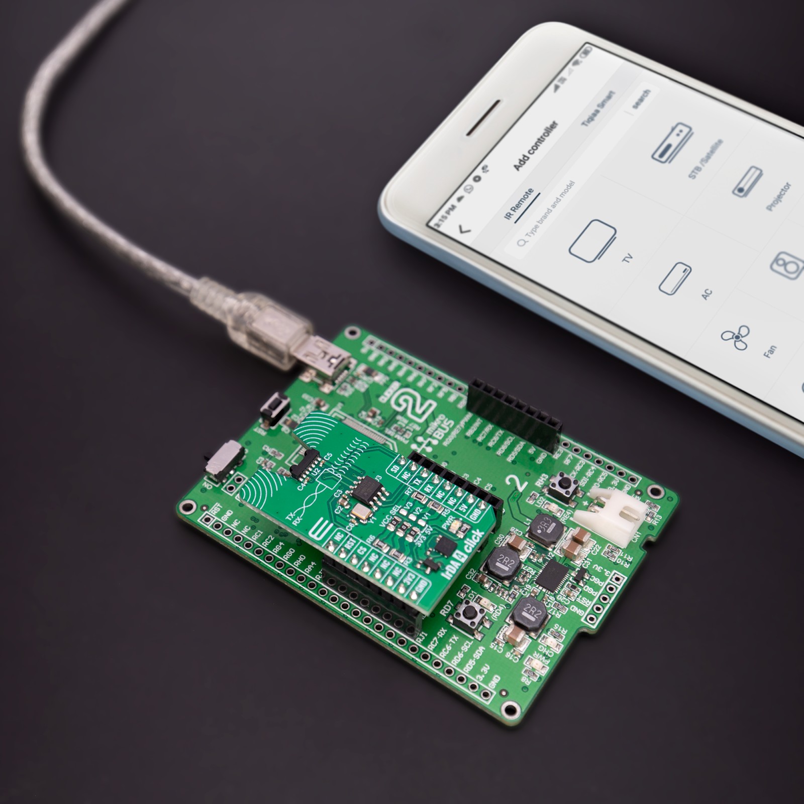
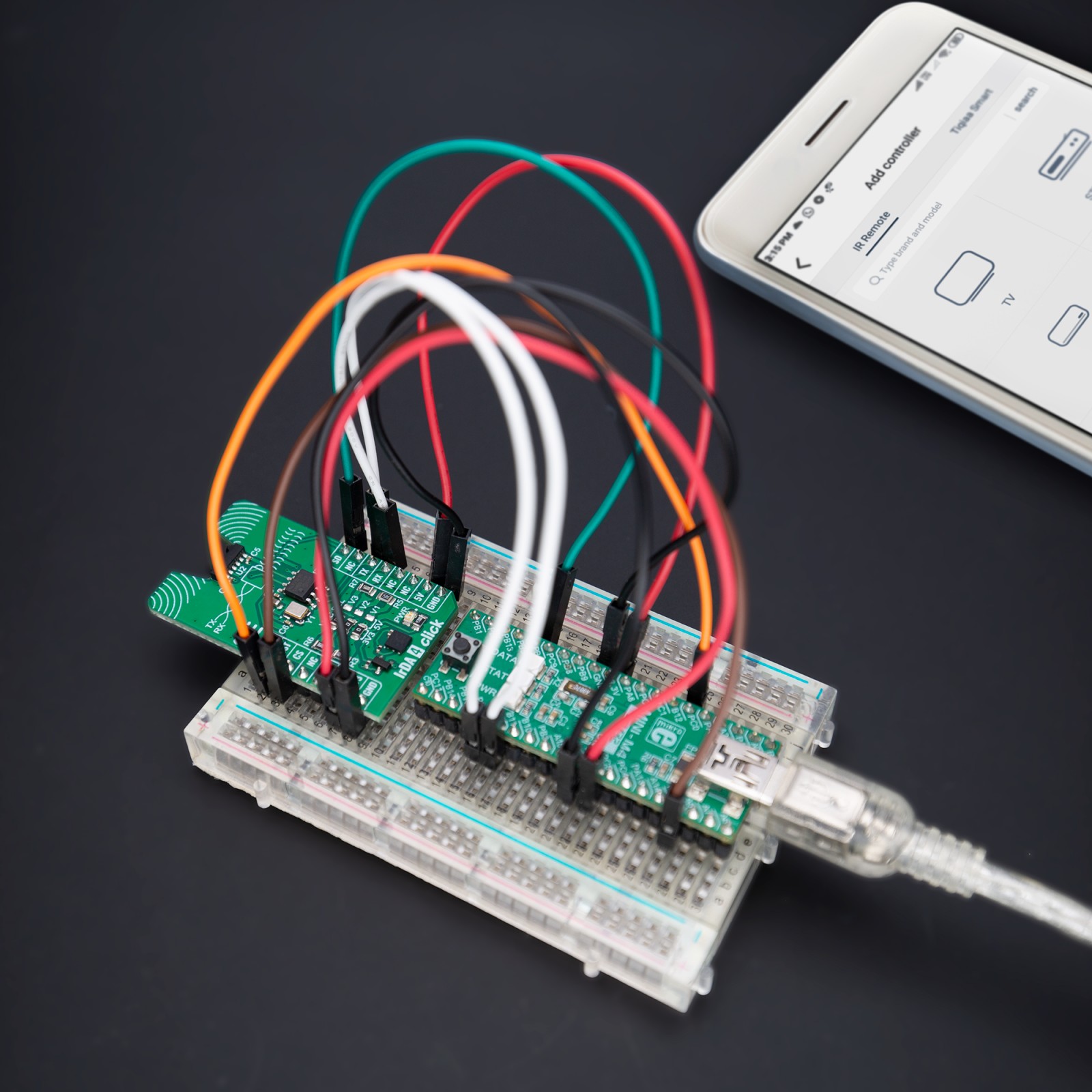
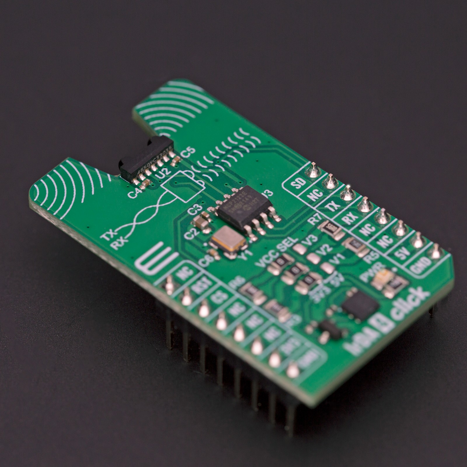
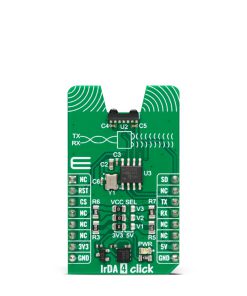
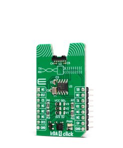
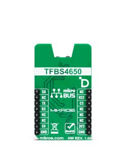
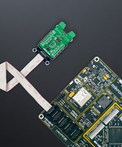
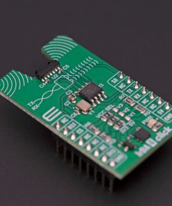
IrDA 4 Click is based on the TFBS4650, an infrared transceiver from Vishay Semiconductors. It is a low-power consumption device with a standard IrDA link distance of 1m. At this distance, the transceiver supports data rates up to 115kbit/s per the IrDA standard. The MCP2122 encodes an asynchronous serial data stream, converting each data bit to the corresponding Infrared (IR) formatted pulse, with received IR pulses decoded back into the corresponding UART formatted serial data. The combination of the MCP2122 and TFBS4650 results in fast and stable infrared data communication covering the full IrDA range in distance and speed.
To communicate with the host MCU, IrDA 4 Click uses MCP2122 and its onboard clock generator for the fastest possible UART performance of 115.200 bps, so it does not need an additional clock signal to be generated by the MCU. The RST pin of the mikroBUS™ socket can reset the MCP2122, while the SD pin with an active HIGH logic state can be used to put the TFBS4650 into a Shutdown state.
This Click board™ can operate with either 3.3V or 5V logic voltage levels selected via the VCC SEL V1 jumper. This way, both 3.3V and 5V capable MCUs can use the communication lines properly. Apart from the V1 jumper, there are two more: V2 and V3. The V2 jumper serves as the main power supply of the TFBS4650, while the V3 jumper allows you to set the voltage specifically for its IRED anode. Each of these positions can be selected independently, allowing you the flexibility to choose the configuration that best suits your requirements. However, the Click board™ comes equipped with a library containing easy-to-use functions and an example code that can be used, as a reference, for further development.
Specifications
Type
Optical
Applications
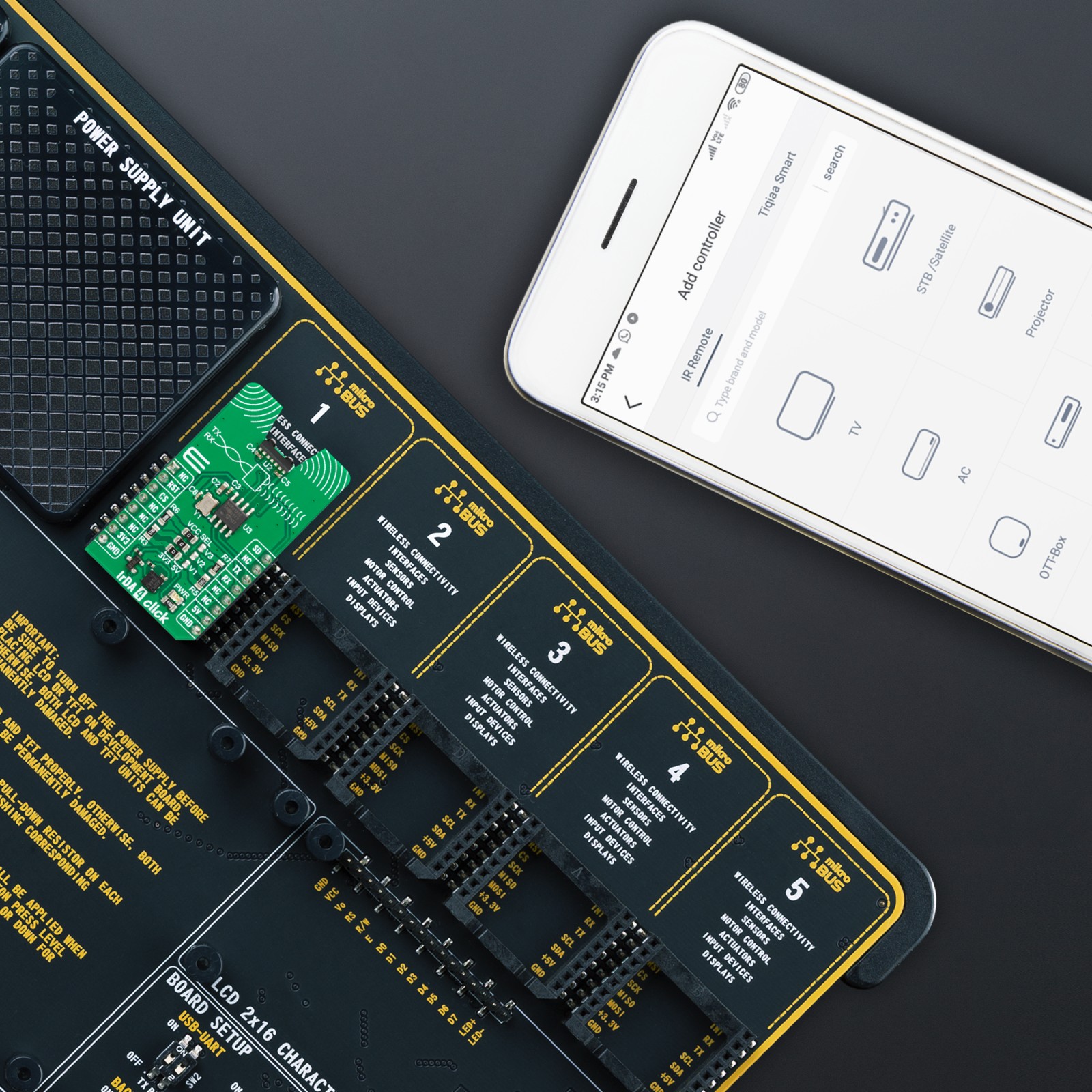
Can be used for the development of short-distance communication and data transfer, or in use in environments where RF is problematic
On-board modules
TFBS4650 – infrared transceiver from Vishay Semiconductors
Key Features
Simple to use UART to IrDA communication, the onboard encoder/decoder takes care of all the communication between the IR transceiver and the MCU, selecting voltages independently for the logic level, IRED anode, and the internal transceiver drive, compliant to the IrDA physical layer, 1m distance, and more
Interface
UART
Feature
ClickID
Compatibility
mikroBUS™
Click board size
M (42.9 x 25.4 mm)
Input Voltage
3.3V or 5V
Pinout diagram
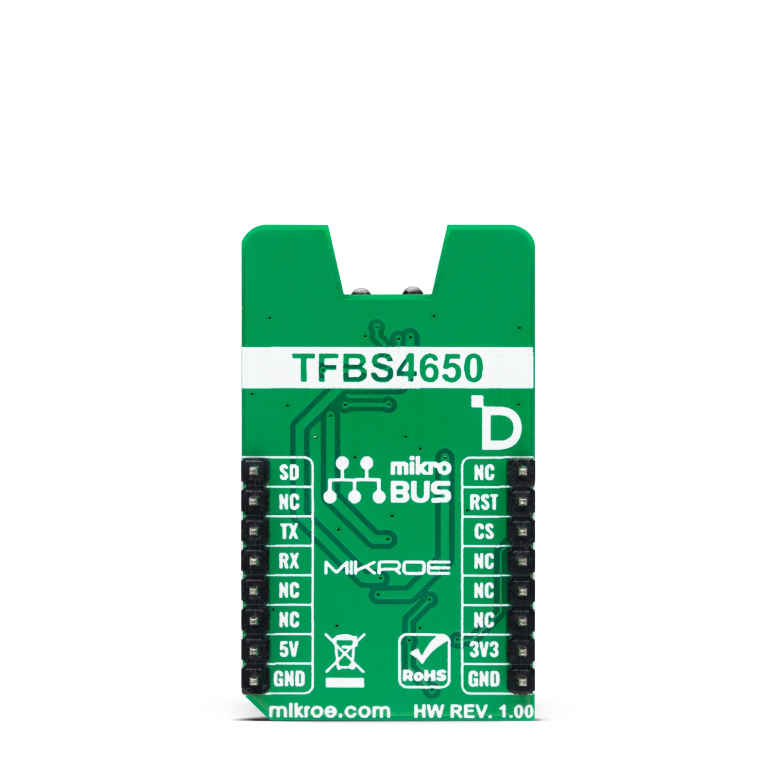
This table shows how the pinout on IrDA 4 Click corresponds to the pinout on the mikroBUS™ socket (the latter shown in the two middle columns).
Onboard settings and indicators
Label | Name | Default | Description |
---|---|---|---|
LD1 | PWR | – | Power LED Indicator |
JP1 | VCC SEL | Left | Logic Level Voltage Selection 3V3/5V: Left position 3V3, Right position 5V |
JP2 | VCC SEL | Left | IRED Voltage Selection 3V3/5V: Left position 3V3, Right position 5V |
JP3 | VCC SEL | Left | TFBS4650 Power Supply Selection 3V3/5V: Left position 3V3, Right position 5V |
IrDA 4 Click electrical specifications
Description | Min | Typ | Max | Unit |
---|---|---|---|---|
Supply Voltage | 3.3 | – | 5 | V |
Distance Range | – | – | 1 | m |
Wavelength | – | 890 | – | nm |
Data Rate | – | – | 115 | kbit/s |
Software Support
We provide a library for the IrDA 4 Click as well as a demo application (example), developed using MIKROE compilers. The demo can run on all the main MIKROE development boards.
Package can be downloaded/installed directly from NECTO Studio Package Manager (recommended), downloaded from our LibStock™ or found on Mikroe github account.
Library Description
This library contains API for IrDA 4 Click driver.
Key functions
-
irda4_generic_write
IrDA 4 data writing function. -
irda4_generic_read
IrDA 4 data reading function. -
irda_hw_reset
IrDA 4 hardware reset function.
Example Description
This example demonstrates the use of IrDA 4 Click board™ by processing the incoming data and displaying them on the USB UART.
void application_task ( void )
{
#if defined( DEMO_APP_TRANSMITTER )
for ( uint8_t n_cnt = 0; n_cnt < 8; n_cnt++ )
{
irda4_generic_write( &irda4, &tx_message[ n_cnt ], 1 );
Delay_ms( 500 );
}
log_printf( &logger, "Message sent rn" );
#else
if ( 1 == irda4_generic_read( &irda4, &rx_message, 1 ) )
{
log_printf( &logger, "%c", rx_message );
}
#endif
}
The full application code, and ready to use projects can be installed directly from NECTO Studio Package Manager (recommended), downloaded from our LibStock™ or found on Mikroe github account.
Other Mikroe Libraries used in the example:
- MikroSDK.Board
- MikroSDK.Log
- Click.IrDA4
Additional notes and informations
Depending on the development board you are using, you may need USB UART click, USB UART 2 Click or RS232 Click to connect to your PC, for development systems with no UART to USB interface available on the board. UART terminal is available in all MIKROE compilers.
mikroSDK
This Click board™ is supported with mikroSDK – MIKROE Software Development Kit. To ensure proper operation of mikroSDK compliant Click board™ demo applications, mikroSDK should be downloaded from the LibStock and installed for the compiler you are using.
For more information about mikroSDK, visit the official page.