Illuminance Click
R440.00 R200.00 ex. VAT
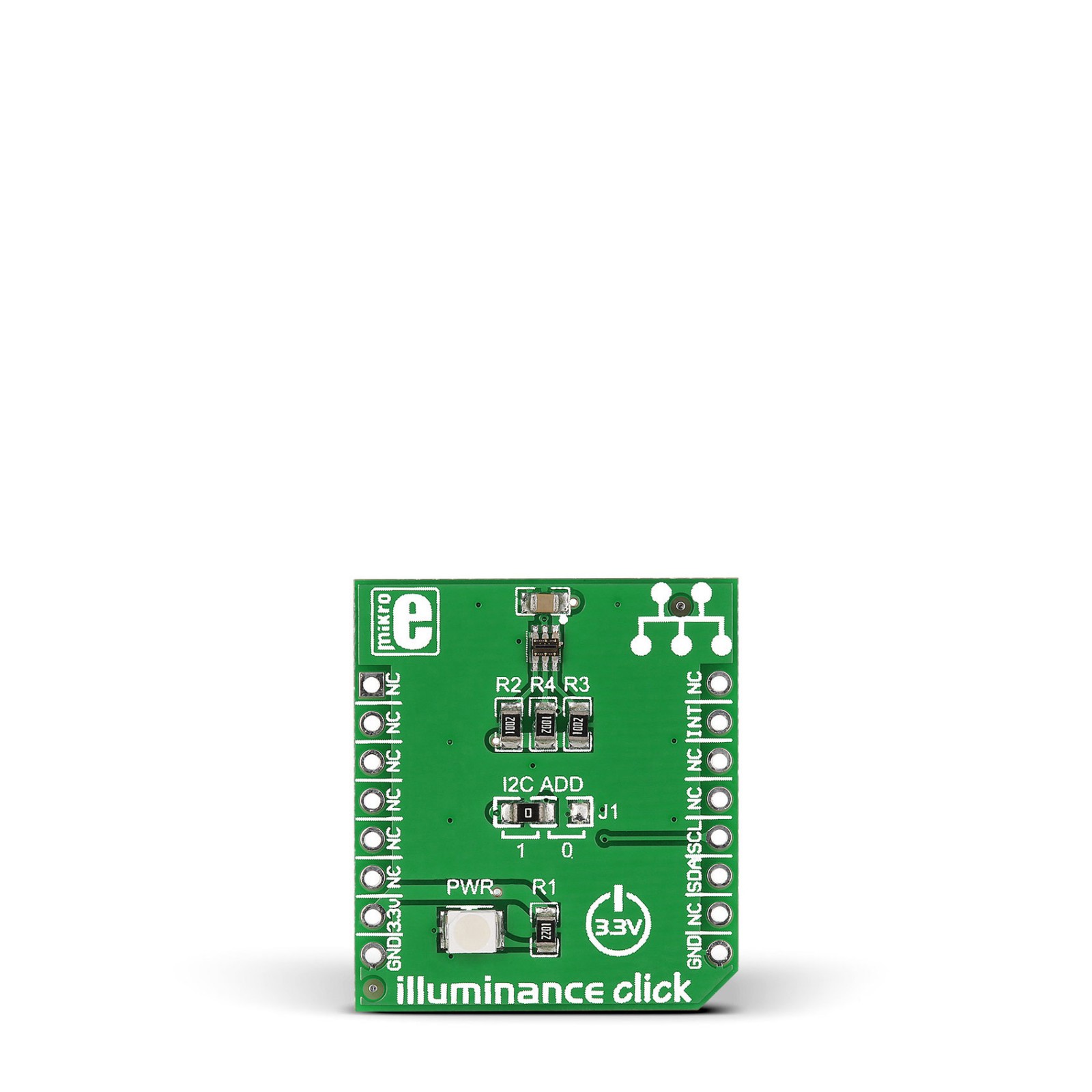
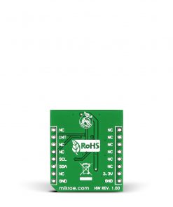
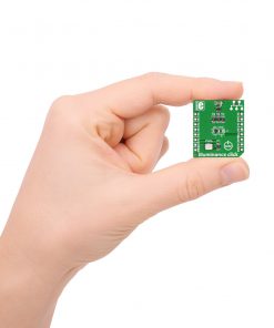
Illuminance Click is a compact add-on board that mimics how humans perceive light. This board features ams AG’s TSL2583, a very-high sensitivity light-to-digital converter that transforms light intensity to a digital signal output capable of the direct I2C interface. It combines one broadband photodiode (visible plus infrared) and one infrared-responding photodiode on a single CMOS integrated circuit capable of providing a near-photopic response over an effective 16-bit dynamic range (16-bit resolution). This Click board™ is suitable for general-purpose light sensing applications to extend battery life and provide optimum viewing in diverse lighting conditions.
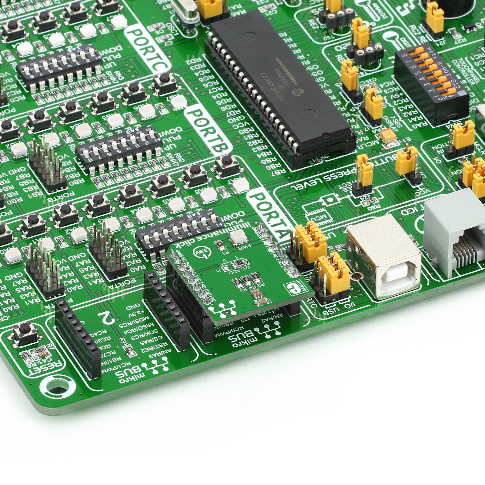
Illuminance Click is supported by a mikroSDK compliant library, which includes functions that simplify software development. This Click board™ comes as a fully tested product, ready to be used on a system equipped with the mikroBUS™ socket.
Stock: 1 available immediately.
How does it work?
Illuminance Click is based on the TSL2583, a high-sensitivity light-to-digital converter from ams AG. The TSL2583 combines one broadband photodiode (visible plus infrared) and one infrared-responding photodiode on a single CMOS integrated circuit capable of providing a near-photopic response over an effective 16-bit dynamic range (16-bit resolution). Two integrating analog-to-digital converters (ADC) convert the photodiode currents to a digital output representing the irradiance measured on each channel. Besides general-purpose light sensing applications, the TSL2583 is explicitly designed for displays (LCD, OLED) to extend battery life and provide optimum viewing in diverse lighting conditions.

The TSL2583 communicates with the MCU using the standard I2C 2-Wire interface with a maximum frequency of 400kHz. Besides, it allows choosing the least significant bit (LSB) of its I2C slave address using the SMD jumper labeled I2C ADD. An integration of both ADC channels co-occurs. Upon completion of the conversion cycle, the conversion result is transferred to the Channel 0 and Channel 1 data registers, respectively. The transfers are double-buffered to ensure that the integrity of the data is maintained. After the transfer, the device automatically begins the next integration cycle.
This sensor also supports an interrupt feature, routed to the INT pin on the mikroBUS™ socket, that simplifies and improves system efficiency by eliminating the need to poll a sensor for a light intensity value. The purpose of the interrupt function is to detect a meaningful change in light intensity, where the user can define the concept of a significant change in light intensity and time or persistence. Users can define a threshold above and below the current light level, where an interrupt generates when the conversion value exceeds either of these limits.
This Click board™ can be operated only with a 3.3V logic voltage level. The board must perform appropriate logic voltage level conversion before using MCUs with different logic levels. However, the Click board™ comes equipped with a library containing functions and an example code that can be used as a reference for further development.
Specifications
Type
Optical
Applications
Can be used for general-purpose light sensing applications
On-board modules
TSL2583 – light-to-digital converter from ams AG
Key Features
Low power consumption, high sensitivity, separate photodiodes (infrared and full-spectrum), approximates human eye response, interrupt feature, I2C interface, and more
Interface
I2C
Feature
No ClickID
Compatibility
mikroBUS™
Click board size
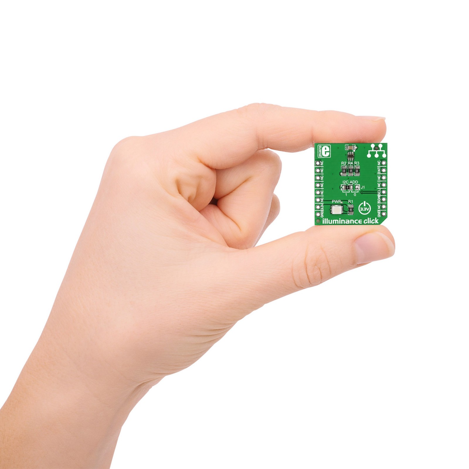
S (28.6 x 25.4 mm)
Input Voltage
3.3V
Pinout diagram
This table shows how the pinout on Illuminance Click corresponds to the pinout on the mikroBUS™ socket (the latter shown in the two middle columns).
Onboard settings and indicators
| Label | Name | Default | Description |
|---|---|---|---|
| LD1 | PWR | – | Power LED Indicator |
| JP1 | I2C ADD | Left | I2C Address Selection 1/0: Left position 1, Right position 0 |
Illuminance Click electrical specifications
| Description | Min | Typ | Max | Unit |
|---|---|---|---|---|
| Supply Voltage | – | 3.3 | – | V |
| Spectral Range | 300 | – | 1100 | nm |
| Peak Wavelength CH0 | – | 625 | – | nm |
| Peak Wavelength CH1 | – | 850 | – | nm |
| Resolution | – | 16 | – | bit |
| Operating Temperature Range | -30 | +25 | +70 | °C |
Software Support
We provide a library for the Illuminance Click as well as a demo application (example), developed using MikroElektronika compilers. The demo can run on all the main MikroElektronika development boards.
Package can be downloaded/installed directly from NECTO Studio Package Manager(recommended way), downloaded from our LibStock™ or found on Mikroe github account.
Library Description
This library contains API for Illuminance Click driver.
Key functions
-
This function gets Visible & Infrared value.
-
This function calculates lux value from the TSL2561 sensor.
Example Description
This example demonstrates basic Illuminance Click functionality – calculates illuminance measured by sensor and logs results to UART Terminal.
 void application_task ( void )
 {
     illuminance_get_result( &illuminance, &value_ch0, &value_ch1 );

     lux_value = illuminance_calculate_lux( ILLUMINANCE_TSL2561_GAIN_0X, ILLUMINANCE_TSL2561_INTEGRATIONTIME_402MS , value_ch0, value_ch1 );
     Delay_ms( 1000 );

     if ( ( ( lux_value - lux_value_old ) > sensitivity ) && ( ( lux_value_old - lux_value ) > sensitivity ) )
     {
         log_printf( &logger, "rn--------------------------------" );
         log_printf( &logger, "rnFull  Spectrum: %u [ lux ]", lux_value );
         log_printf( &logger, "rnVisible  Value: %u [ lux ]", value_ch0 - value_ch1 );
         log_printf( &logger, "rnInfrared Value: %u [ lux ]", value_ch1 );
         log_printf( &logger, "rn--------------------------------rn" );

         lux_value_old = lux_value;
     }
 }
The full application code, and ready to use projects can be installed directly from NECTO Studio Package Manager(recommended way), downloaded from our LibStock™ or found on Mikroe github account.
Other Mikroe Libraries used in the example:
- MikroSDK.Board
- MikroSDK.Log
- Click.Illuminance
Additional notes and informations
Depending on the development board you are using, you may need USB UART click, USB UART 2 Click or RS232 Click to connect to your PC, for development systems with no UART to USB interface available on the board. UART terminal is available in all MikroElektronika compilers.
mikroSDK
This Click board™ is supported with mikroSDK – MikroElektronika Software Development Kit. To ensure proper operation of mikroSDK compliant Click board™ demo applications, mikroSDK should be downloaded from the LibStock and installed for the compiler you are using.
For more information about mikroSDK, visit the official page.
Resources
Downloads
| Weight | 30 g |
|---|---|
| Brand | MikroElektronika |

