How does it work?
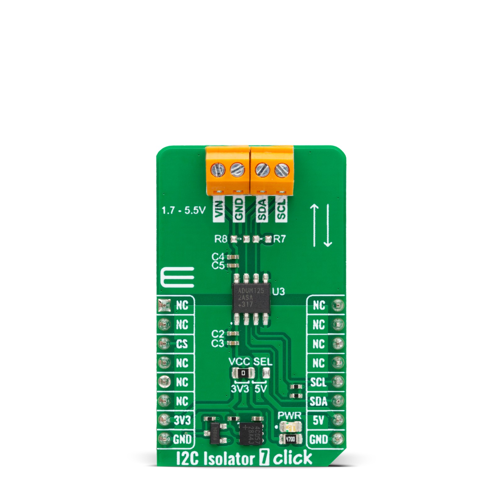
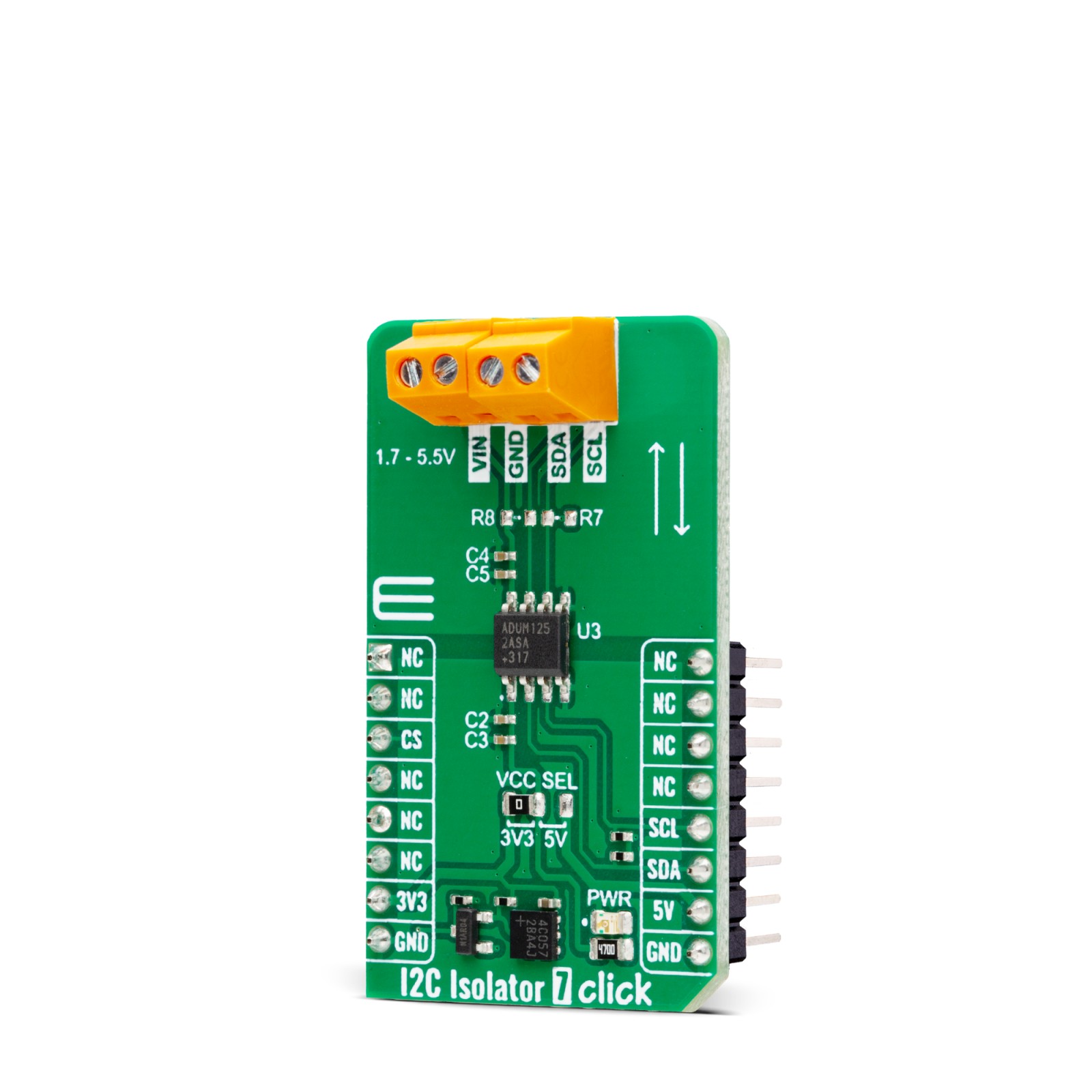
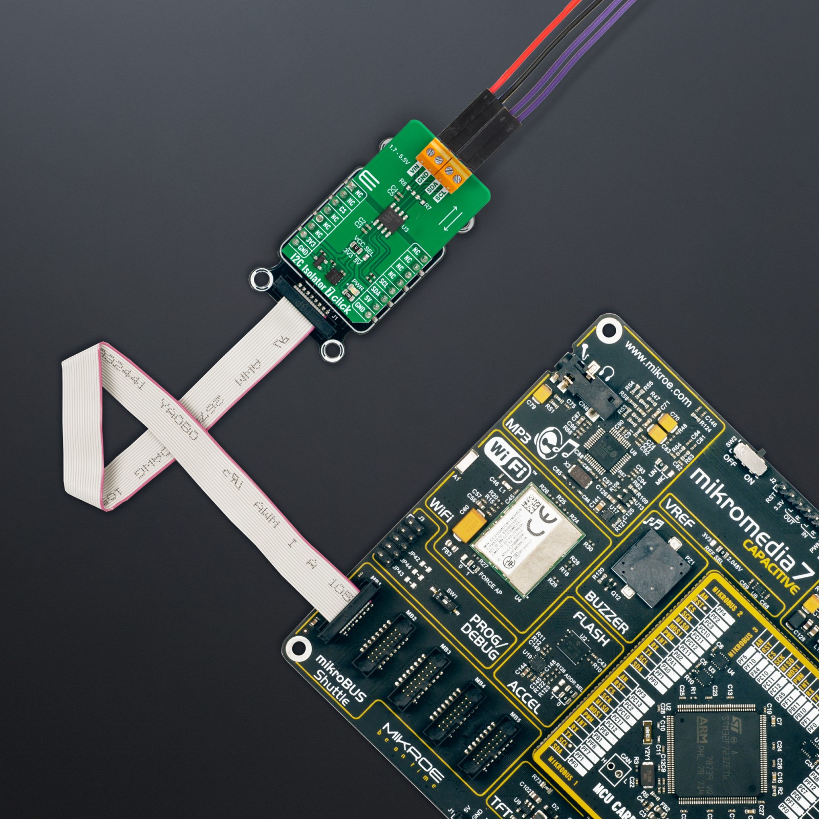
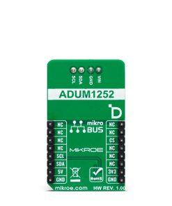
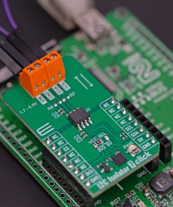
I2C Isolator 7 Click is based on the ADuM1252, an ultra-low power, bidirectional I2C isolator from Analog Devices. It features independent power supplies on both sides. Side 1 is reserved for 3.3V and 5V of mikroBUS™ socket rails, while side 2 can be supplied in a range of 1.71V up to 5.5V. To prevent latch-up action, its side 1 outputs comprise a special buffer that regulates the logic-low voltage, and the input logic-low threshold is lower than the output logic-low voltage. In addition, side 2 features conventional buffers that do not regulate logic-low output voltage.
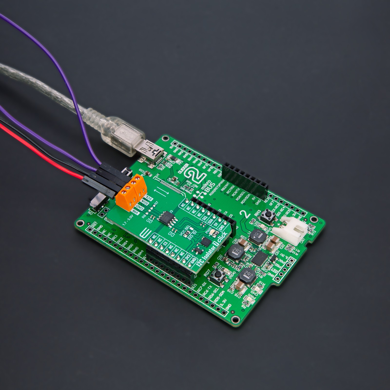
I2C Isolator 7 Click uses a standard 2-Wire I2C interface to allow the host MCU to have an isolated bidirectional data transfer with a connected I2C device to the I2C terminals. As we mentioned, besides the I2C bus, the power supply is isolated, too. Places for optional pull-ups on the I2C bus are left unpopulated. You can solder resistors according to your needs.
This Click board™ can operate with either 3.3V or 5V logic voltage levels selected via the VCC SEL jumper. This way, both 3.3V and 5V capable MCUs can use the communication lines properly. Also, this Click board™ comes equipped with a library containing easy-to-use functions and an example code that can be used as a reference for further development.
Specifications
Type
I2C,Isolators
Applications
Can be used for the development of applications based on transferring digital signals between circuits with different power domains at ambient temperatures
On-board modules
ADuM1252 – ultra-low power, bidirectional I2C isolator from Analog Devices
Key Features
Two bidirectional open-drain channels for applications such as I2C, wide independent supply range, especially for side 2, enhanced hot-swappable side 2 IO, strong current sinking, robust galvanic isolation of digital signals, ultra-low power consumption, and more
Interface
I2C
Feature
ClickID
Compatibility
mikroBUS™
Click board size
M (42.9 x 25.4 mm)
Input Voltage
3.3V or 5V,External
Pinout diagram
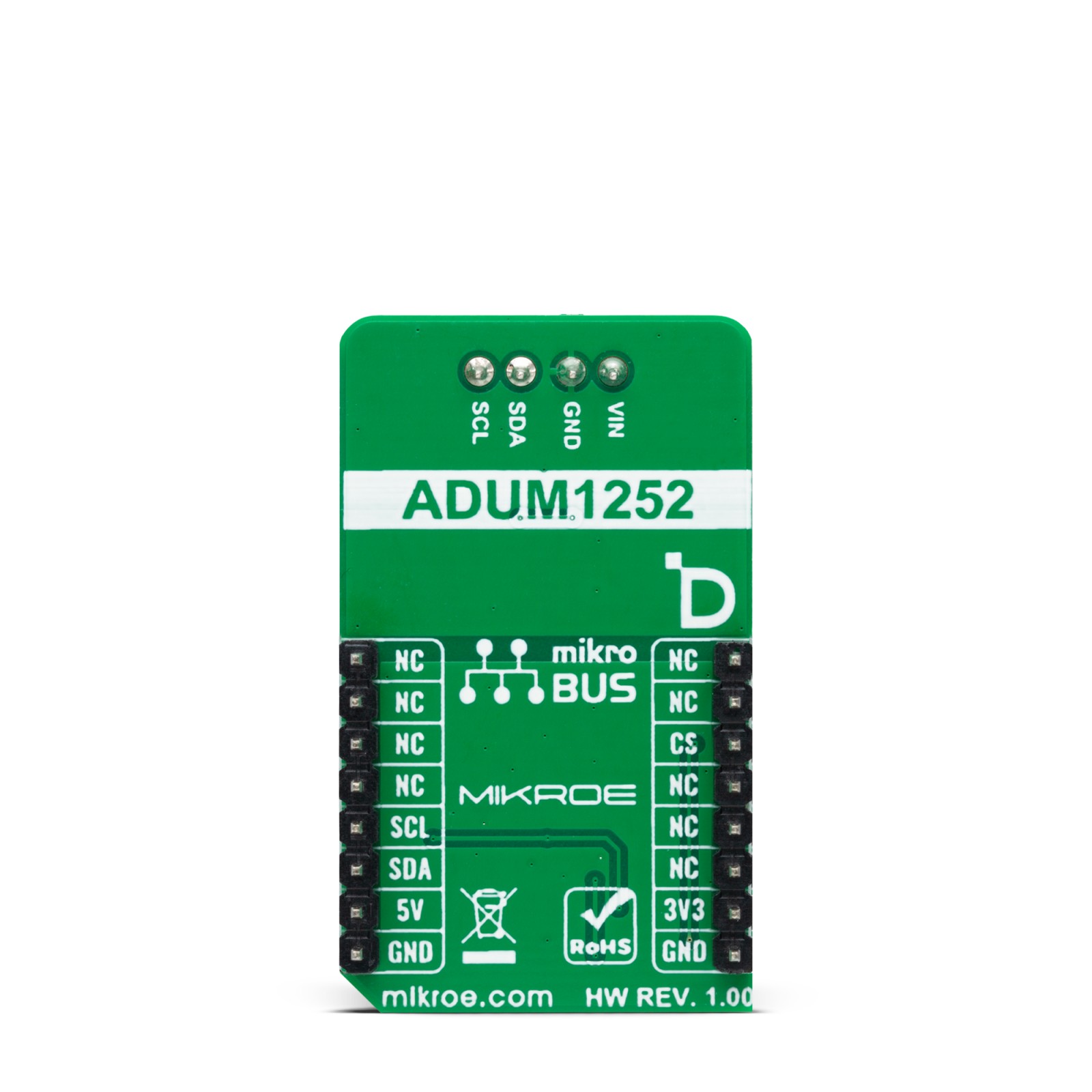
This table shows how the pinout on I2C Isolator 7 Click corresponds to the pinout on the mikroBUS™ socket (the latter shown in the two middle columns).
Onboard settings and indicators
Label | Name | Default | Description |
---|---|---|---|
LD1 | PWR | – | Power LED Indicator |
JP1 | VCC SEL | Left | Power/Logic Voltage Level Selection 3V3/5V: Left position 3V3, Right position 5V |
I2C Isolator 7 Click electrical specifications
Description | Min | Typ | Max | Unit |
---|---|---|---|---|
Supply Voltage | 3.3 | – | 5 | V |
External Power Supply | 1.71 | – | 5.5 | V |
Maximum Data Rate | – | – | 2 | MHz |
Galvanic Isolation | – | – | 445 | VRMS |
Software Support
We provide a library for the I2C Isolator 7 Click as well as a demo application (example), developed using MIKROE compilers. The demo can run on all the main MIKROE development boards.
Package can be downloaded/installed directly from NECTO Studio Package Manager (recommended), downloaded from our LibStock™ or found on Mikroe github account.
Library Description
This library contains API for I2C Isolator 7 Click driver.
Key functions
-
i2cisolator7_generic_write
This function shall generate a START signal, followed by len number of writes from data_in. -
i2cisolator7_generic_read
This function shall generate a START signal, followed by len number of reads from the bus placing the data in data_out. -
i2cisolator7_write_then_read
This function performs a write operation followed by a read operation on the bus by using I2C serial interface.
Example Description
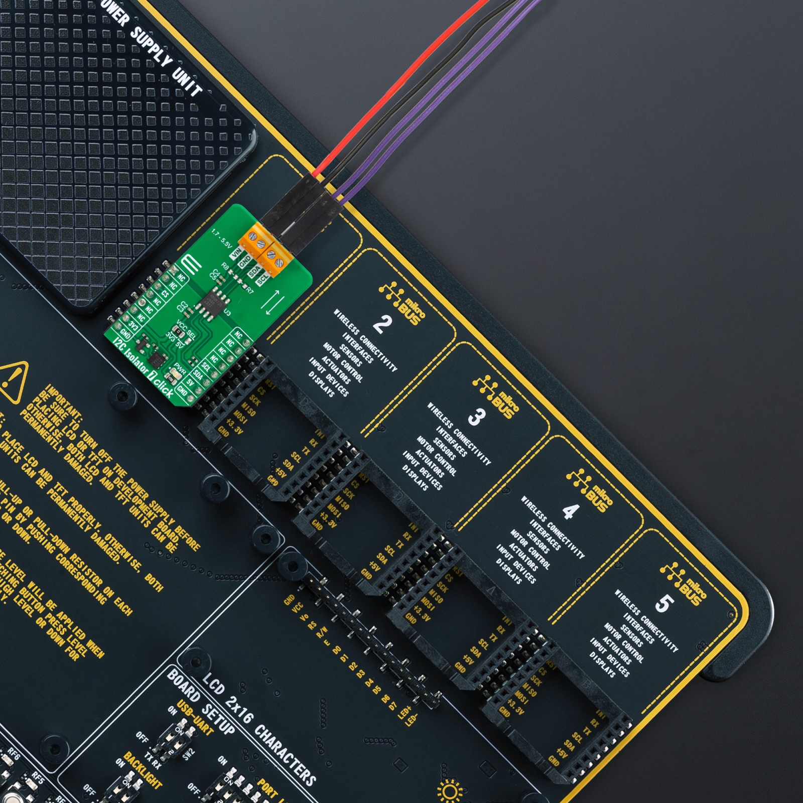
This demo application shows an example of an I2C Isolator 7 Click wired to the PRESS Click board™ for reading device ID (Who am I). The library also includes an I2C writing and reading functions.
void application_task ( void )
{
uint8_t device_id = 0;
uint8_t reg = PRESS_REG_WHO_AM_I;
if ( I2CISOLATOR7_OK == i2cisolator7_write_then_read( &i2cisolator7, ®, 1, &device_id, 1 ) )
{
if ( PRESS_WHO_AM_I == device_id )
{
log_printf( &logger, " Device ID: 0x%.2Xrn", ( uint16_t ) device_id );
log_printf( &logger, "---------------------rn" );
}
}
Delay_ms( 1000 );
}
The full application code, and ready to use projects can be installed directly from NECTO Studio Package Manager (recommended), downloaded from our LibStock™ or found on Mikroe github account.
Other Mikroe Libraries used in the example:
- MikroSDK.Board
- MikroSDK.Log
- Click.I2CIsolator7
Additional notes and informations
Depending on the development board you are using, you may need USB UART click, USB UART 2 Click or RS232 Click to connect to your PC, for development systems with no UART to USB interface available on the board. UART terminal is available in all MIKROE compilers.
mikroSDK
This Click board™ is supported with mikroSDK – MIKROE Software Development Kit. To ensure proper operation of mikroSDK compliant Click board™ demo applications, mikroSDK should be downloaded from the LibStock and installed for the compiler you are using.
For more information about mikroSDK, visit the official page.