How does it work?
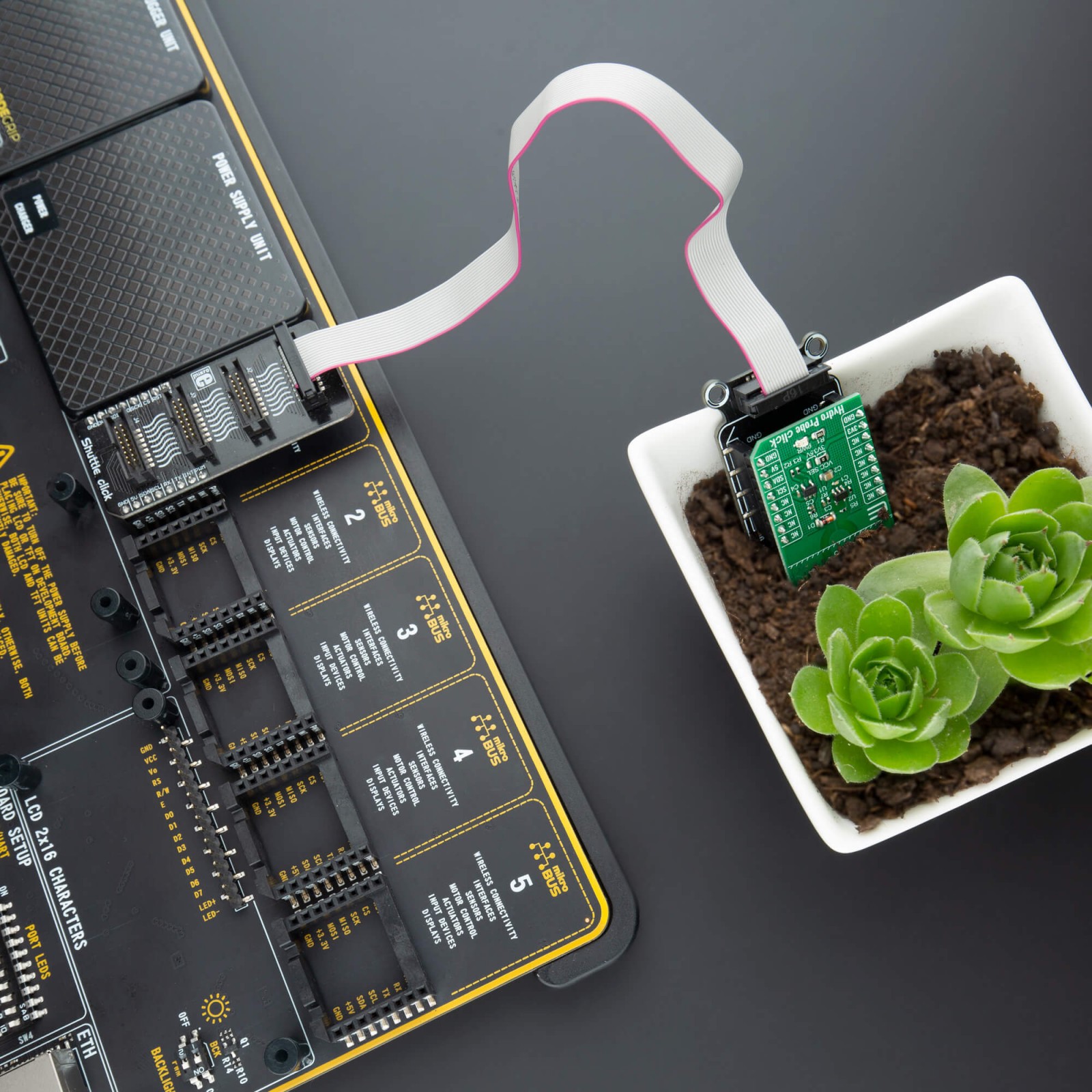
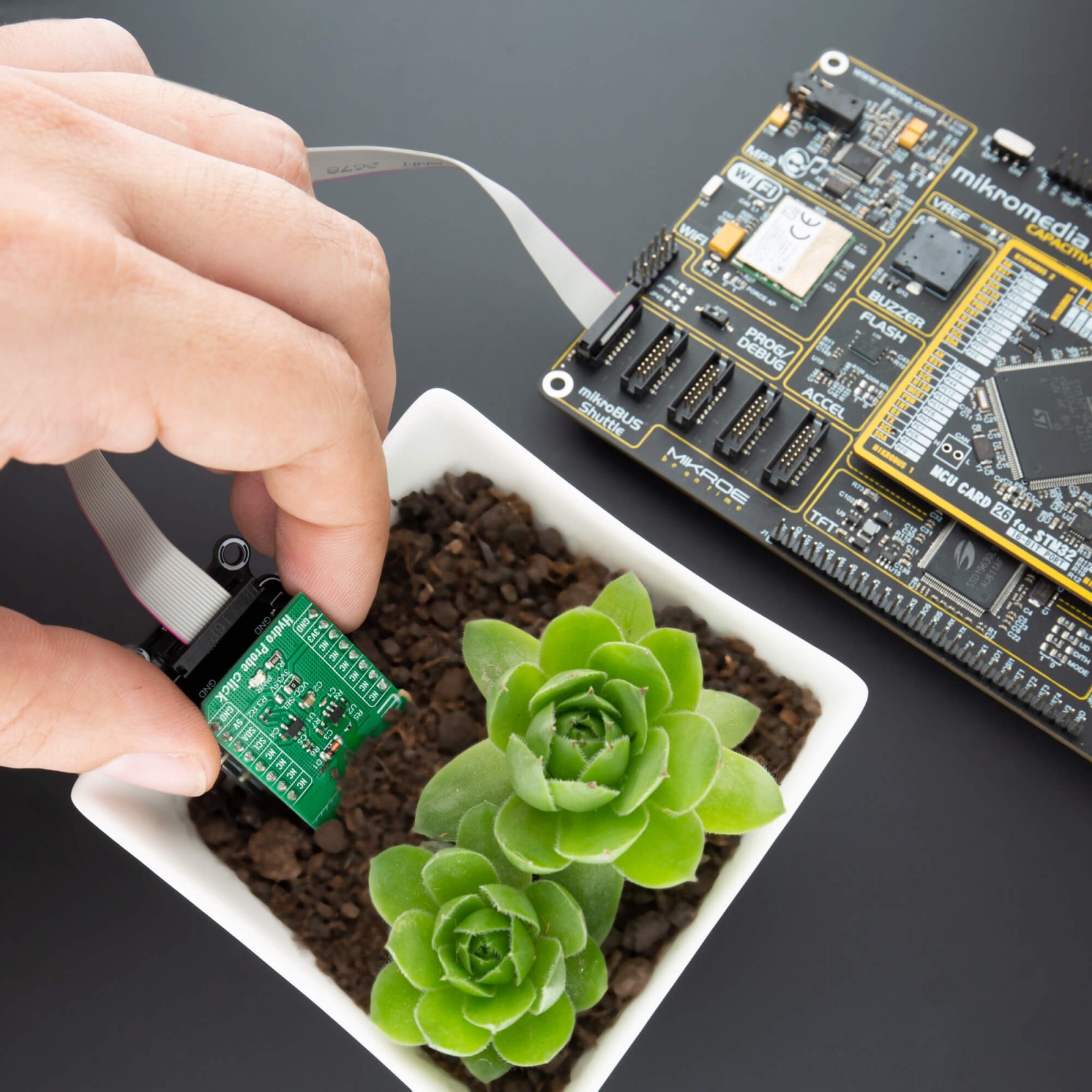
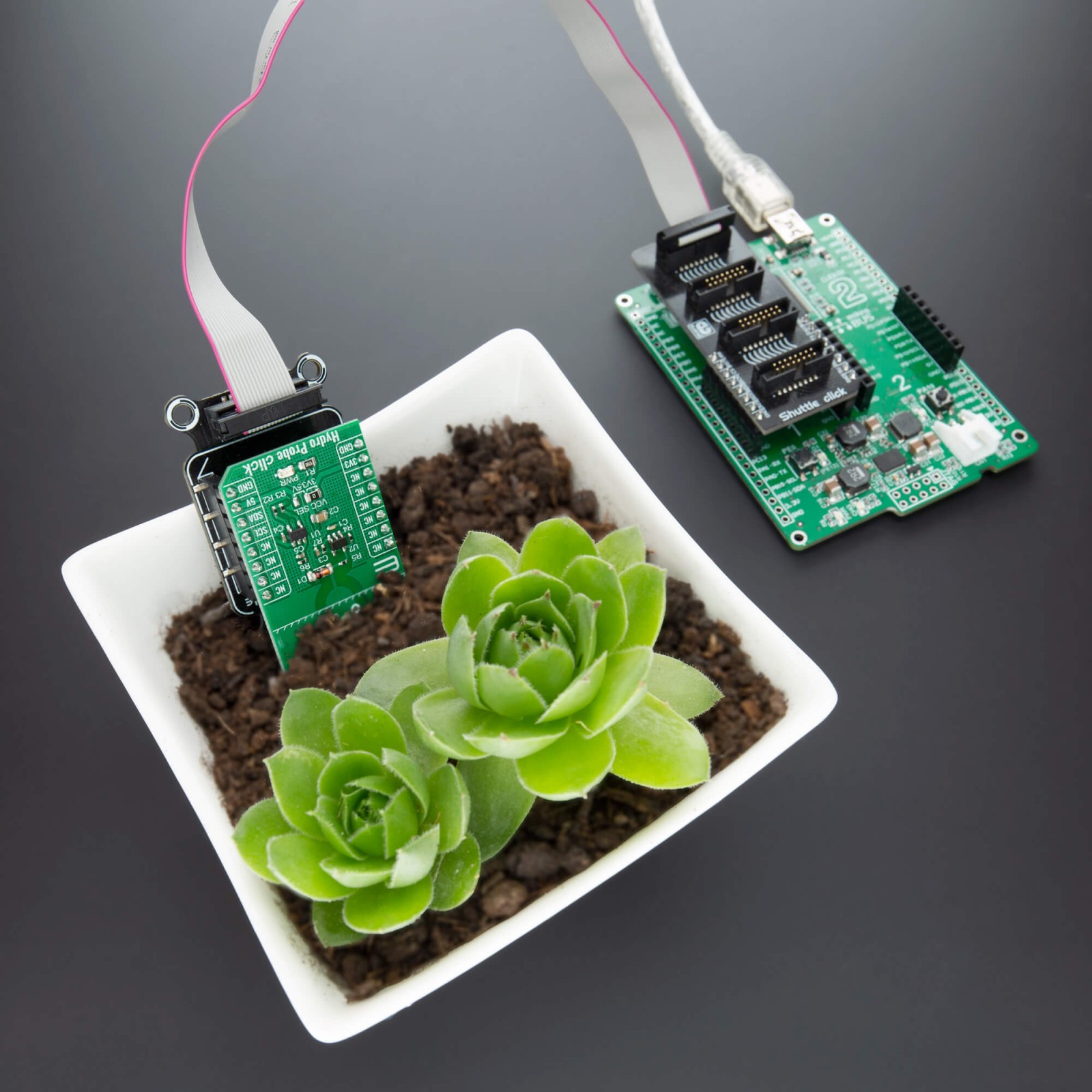
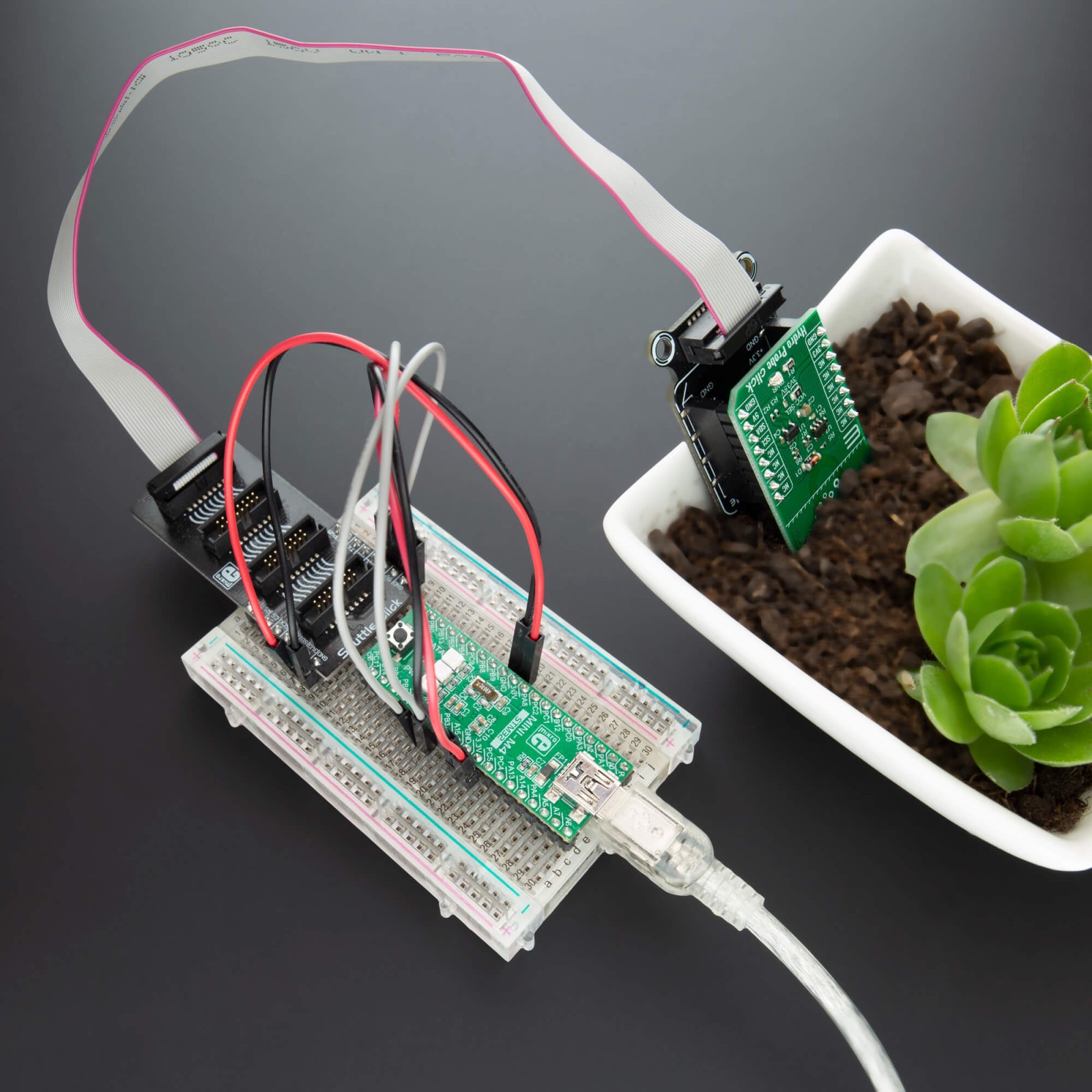
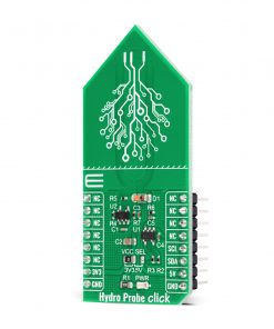
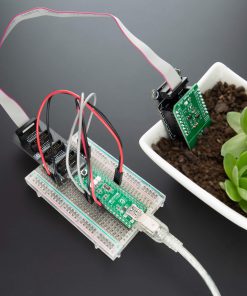
Hydro Probe Click uses the capacitive soil moisture sensor based on capacitive changes that are used to detect the volumetric water content of the soil. It based its operation on capacitive measurement, which has a great advantage over resistive measurement. Compared with resistive soil moisture sensors, capacitive sensors do not require direct exposure of the metal electrodes, which can significantly reduce the erosion of the electrodes. This Click board™ can only qualitatively test the humidity of the soil and can’t measure quantitatively. When the humidity of the soil rises, the value of the output decreases; conversely, when the humidity decreases, the output value becomes higher. It operates with a flexible power supply voltage range which makes it suitable for 3.3V and 5V MCUs.
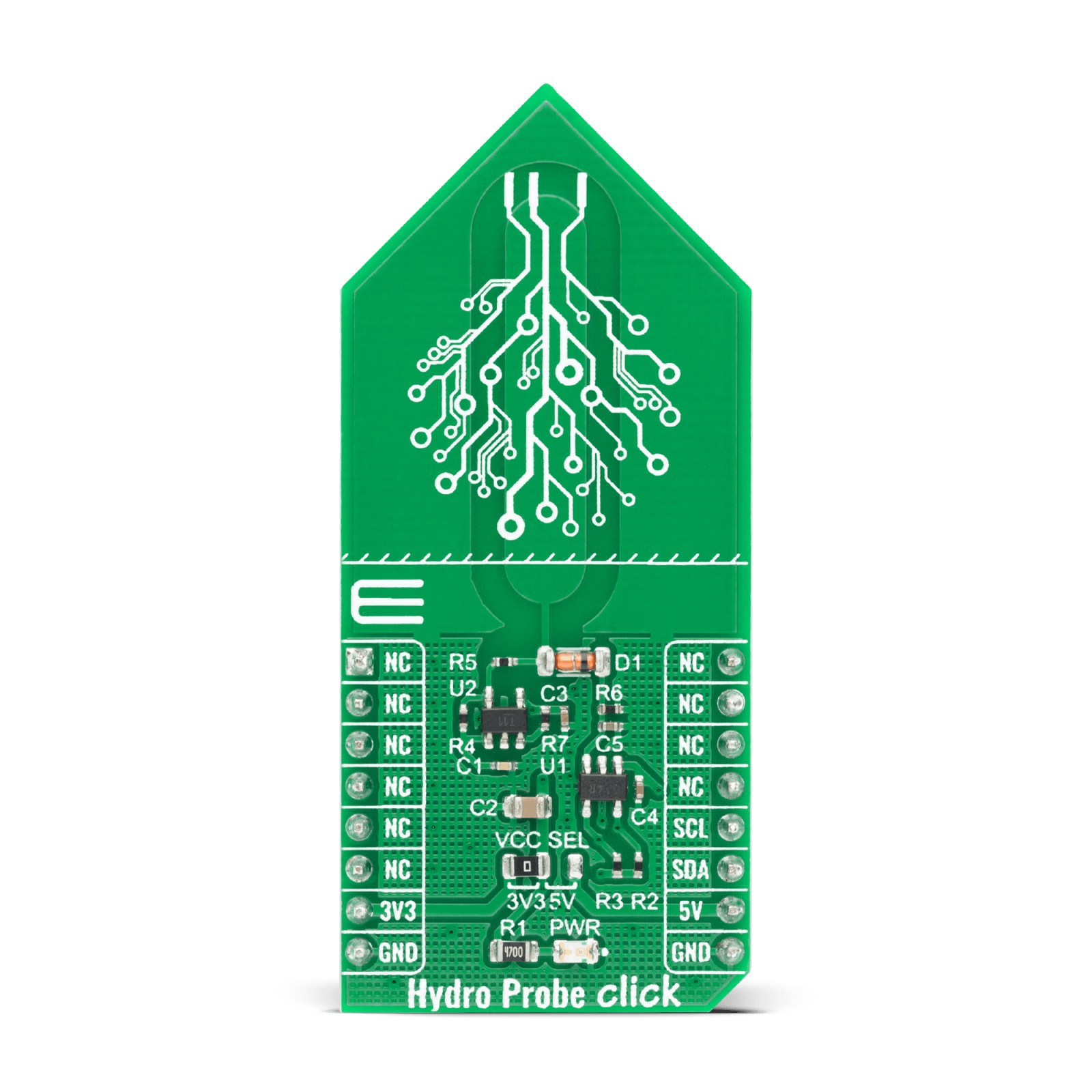
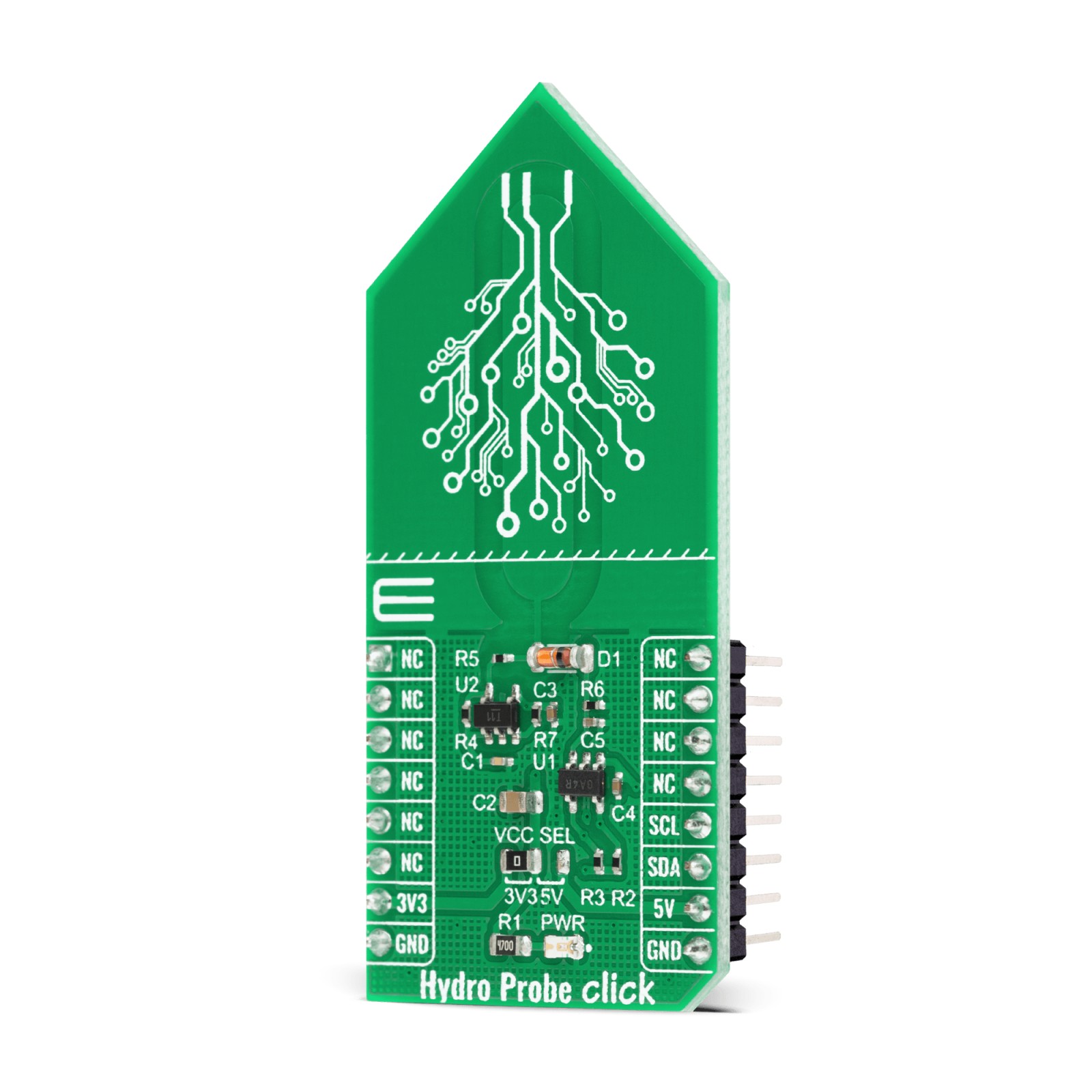
Hydro Probe Click performs its function as capacitive soil moisture sensor by using two main components, CMOS RC oscillator MIC1557 and 12-bit A/D converter MCP3221 with I2C serial interface. Oscillator frequency is set to 600kHz. From the oscillator, a signal goes to the soil moisture probe through a 10k resistor, these two elements act as a low pass filter for the oscillator signal. The output analog signal from the capacitive probe goes through diode to the MCP3221, A/D converter with 12-bit resolution, which converts that data and sends it to MCU. Communication to the MCP3221 is performed using a 2-wire I2C serial interface with available standard (100 kHz) or fast (400 kHz) mode. To be sure that you received correct data, calibration of the Hydro Probe Click needs to be done. The final output value is affected by probe insertion depth and how tight the soil packed around it is. It‘s recommended that the probe should not be placed on the depth which crosses the limit line on the Click board.
This Click board™ uses the I2C communication interface and can be supplied and interfaced with both 3.3V and 5V supply voltage. The on board SMD jumper labeled as VCC SEL allows voltage selection for interfacing with both 3.3V and 5V microcontrollers. More information about integrated circuits on this board can be found in the attached datasheets. However, this Click board™ comes equipped with a library that contains easy to use functions and a usage example that may be used as a reference for the development.
Specifications
Type
Environmental
Applications
Can be used in agriculture usage, household usage for gardeners, research and forecast, and many more.
On-board modules
Hydro Probe Click uses the MIC1557 and MCP3221 IC’s.
Key Features
Digital reading of soil moisture.
Interface
I2C
Feature
No ClickID
Compatibility
mikroBUS™
Click board size
L (57.15 x 25.4 mm)
Input Voltage
3.3V,5V
Pinout diagram
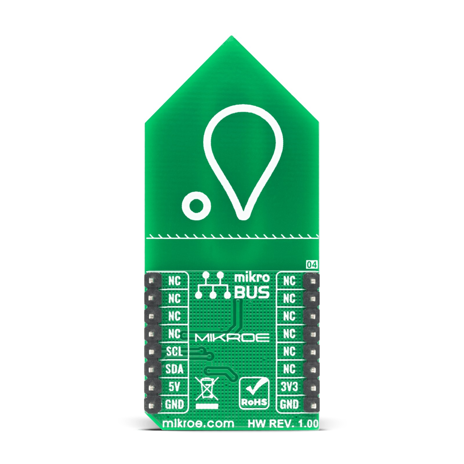
This table shows how the pinout on Hydro Probe Click corresponds to the pinout on the mikroBUS™ socket (the latter shown in the two middle columns).
Onboard settings and indicators
Label | Name | Default | Description |
---|---|---|---|
LD1 | PWR | – | Power LED Indicator |
JP1 | VCC SEL | Left | Power supply voltage selection: left position 3V3, right position 5V |
Software Support
We provide a library for the Hydro Probe Click on our LibStock page, as well as a demo application (example), developed using MikroElektronika compilers. The demo can run on all the main MikroElektronika development boards.
Library Description
The library covers all the necessary functions that enables the usage of the Hydro Probe Click board. It offers reading from output register, calulation for average value from 100 raw reads,functions for maximum and mimimum values from 100 raw reads and calculations that result in environment moisture content in percents.
Key functions:
uint8_t hydroprobe_rel_env_hum ( uint16_t dry_val, uint16_t wet_val );
– Function is used to get environment moisture content in percents.uint16_t hydroprobe_min_val ( );
– Function is used to read minimum value from 100 raw reads.uint16_t hydroprobe_max_val ( );
– Function is used to read maximum value from 100 raw reads.
Examples description
The application is composed of three sections :
- System Initialization – Initializes I2C module and LOG structure.
- Application Initialization – Initalizes I2C driver, prerforms calibration and makes an initial log.
- Application Task – (code snippet) This example shows the capabilities of the Hydro Probe click by measuring environment moisture content and displaying it in percent via USART terminal.
void application_task ( ) { humy_val = hydroprobe_rel_env_hum( dry_val, wet_val ); WordToStr( humy_val, log_txt ); mikrobus_logWrite( "Environment moisture content: ", _LOG_TEXT ); Ltrim( log_txt ); mikrobus_logWrite( log_txt, _LOG_TEXT ); mikrobus_logWrite( "%", _LOG_LINE ); mikrobus_logWrite( "------------------------------", _LOG_LINE ); Delay_ms( 1000 ); }
Additional Functions :
- void hydroprobe_calib ( ) – Function is used to calibrate measurement.
The full application code, and ready to use projects can be found on our LibStock page.
Other mikroE Libraries used in the example:
- I2C
- UART
- Conversions
Additional notes and informations
Depending on the development board you are using, you may need USB UART click, USB UART 2 click or RS232 click to connect to your PC, for development systems with no UART to USB interface available on the board. The terminal available in all MikroElektronika compilers, or any other terminal application of your choice, can be used to read the message.
mikroSDK
This Click board™ is supported with mikroSDK – MikroElektronika Software Development Kit. To ensure proper operation of mikroSDK compliant Click board™ demo applications, mikroSDK should be downloaded from the LibStock and installed for the compiler you are using.
For more information about mikroSDK, visit the official page.