How does it work?
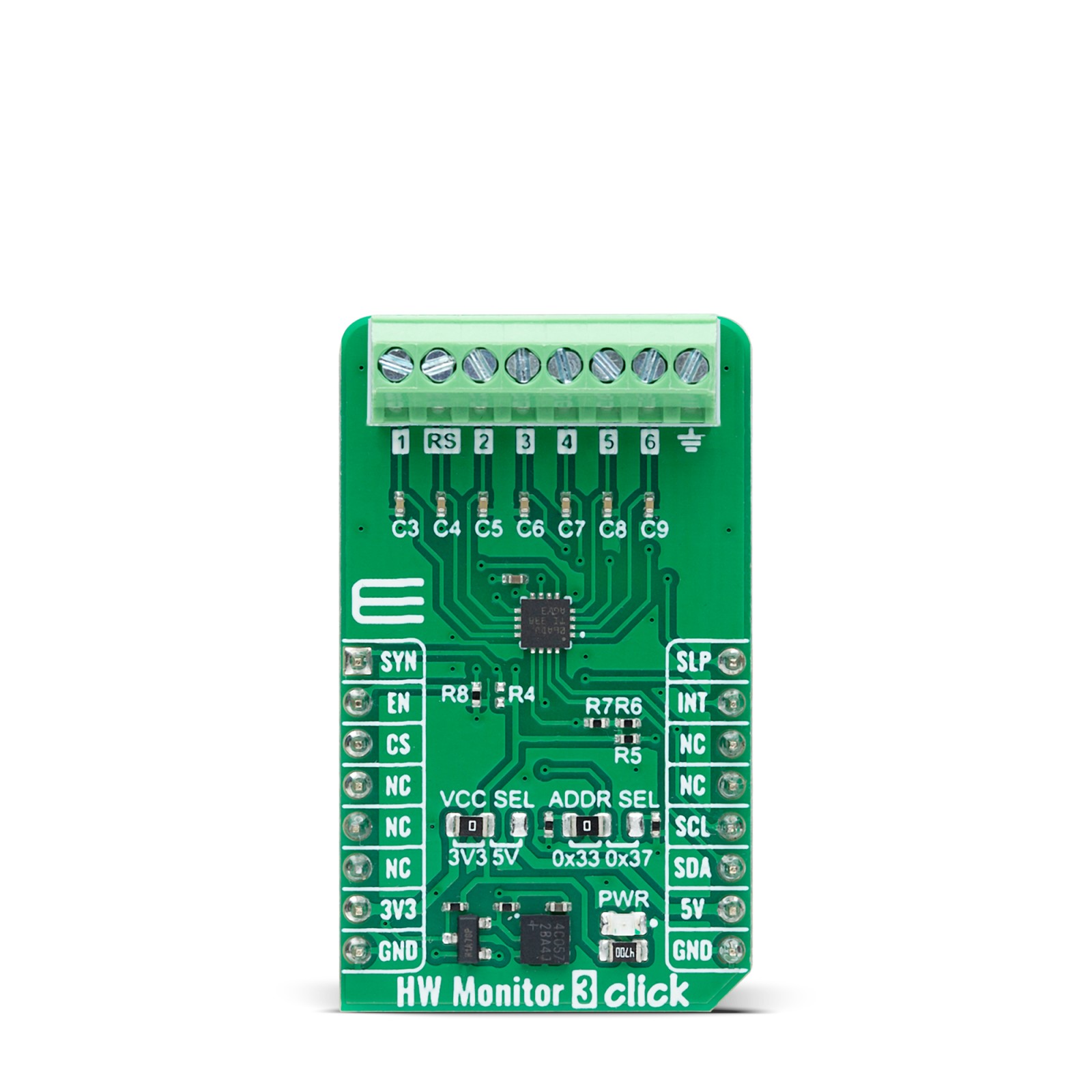
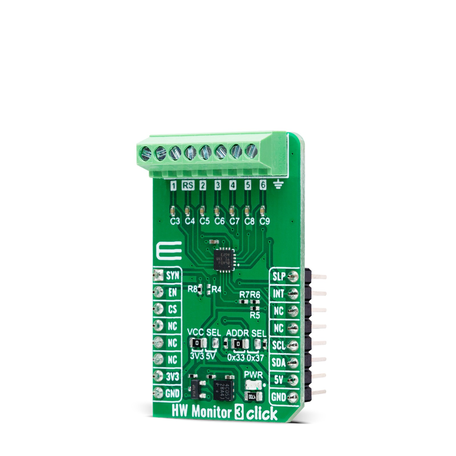
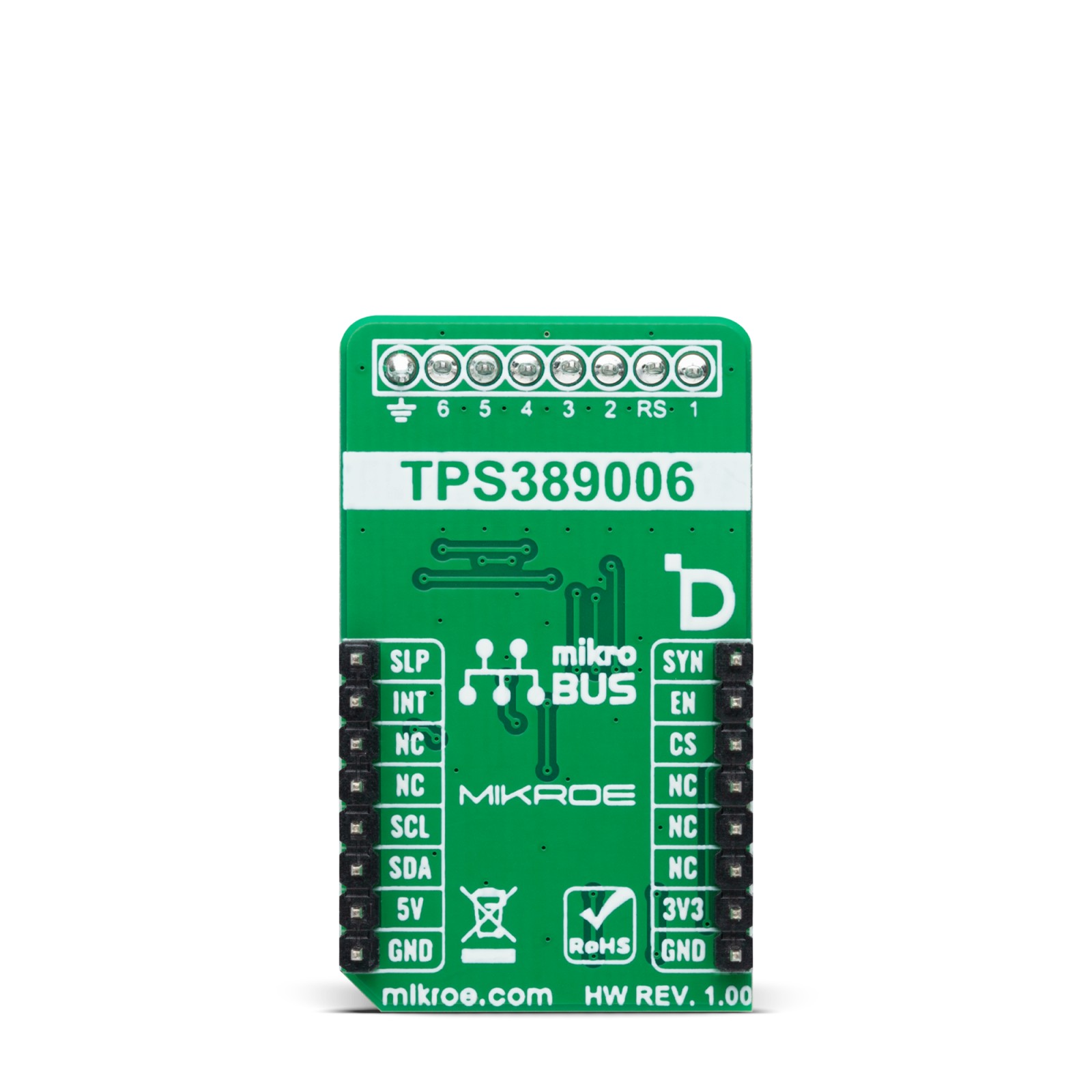
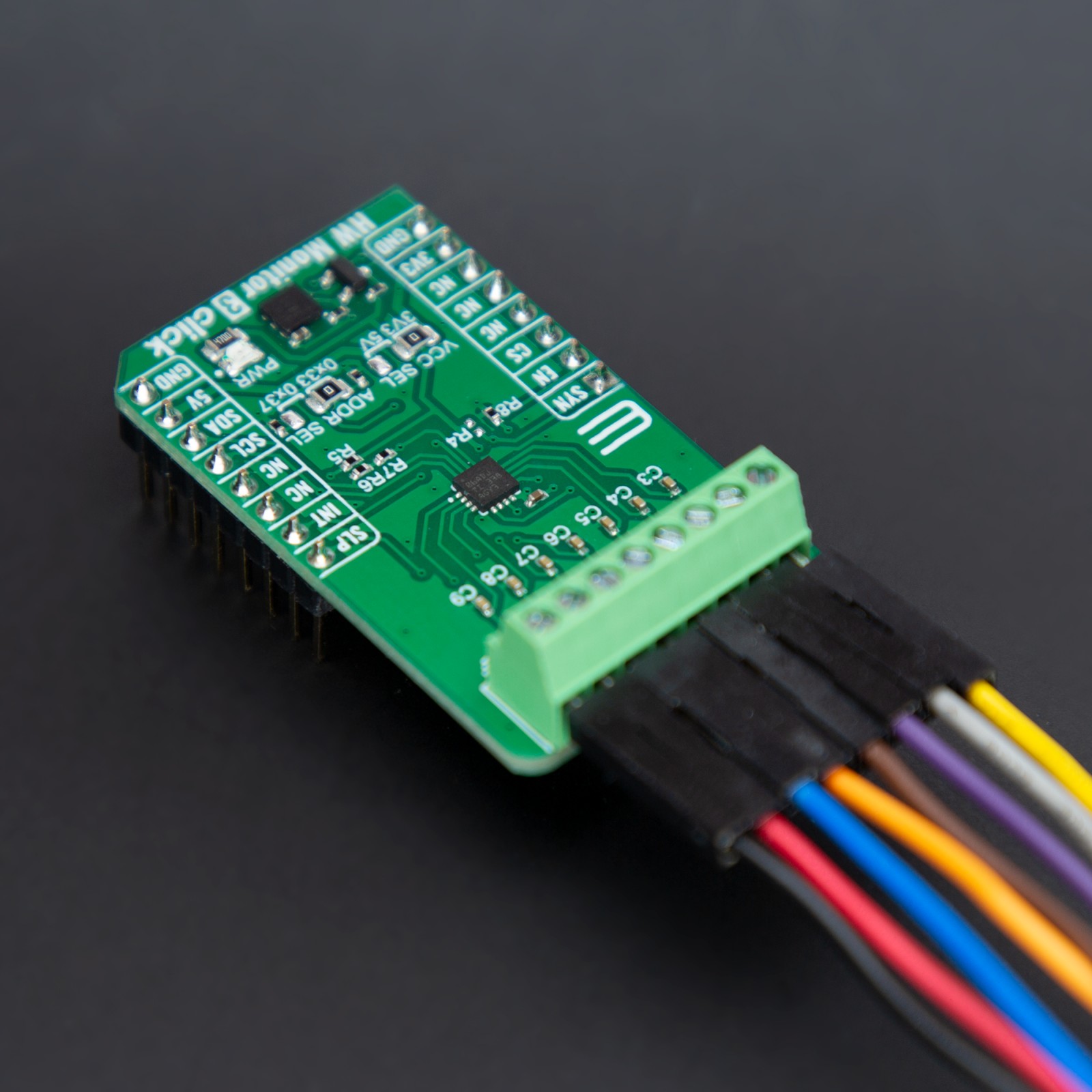
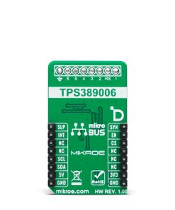
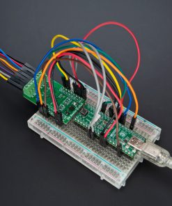
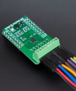
HW Monitor 3 Click is based on the TPS389006, a six-channel window voltage supervisor and monitor IC from Texas Instruments. This I2C-programmable device is engineered to provide precision voltage monitoring for systems operating on low-voltage supply rails with tight tolerance margins. The IC’s thresholds for overvoltage and undervoltage conditions are internally set using precision resistors, providing ±6mV accuracy across a wide temperature range (-40°C to +125°C). It supports voltage levels with fixed window thresholds in fine steps, offering 5mV granularity for inputs between 0.2V and 1.475V or 20mV steps for higher ranges from 0.8V to 5.5V. The device also incorporates a 2.48V undervoltage lockout (UVLO) feature, ensuring stable operation in critical conditions. With compliance with SIL-3 safety standards, this board is tailored for applications requiring the highest reliability and safety, such as medical devices, industrial robotics, server switches, and motor drivers.
The TPS389006 offers exceptional performance with integrated features for robust error detection and monitoring. It includes two remote sense pins for voltage measurement at high-current core rails, compensating for voltage drops across PCB traces. This ensures highly accurate monitoring, making it ideal for systems demanding precise power management. The built-in CRC error checking and sequence logging capabilities track system states during power-up and power-down events, while an integrated ADC provides real-time voltage readouts for additional redundancy in error checking.
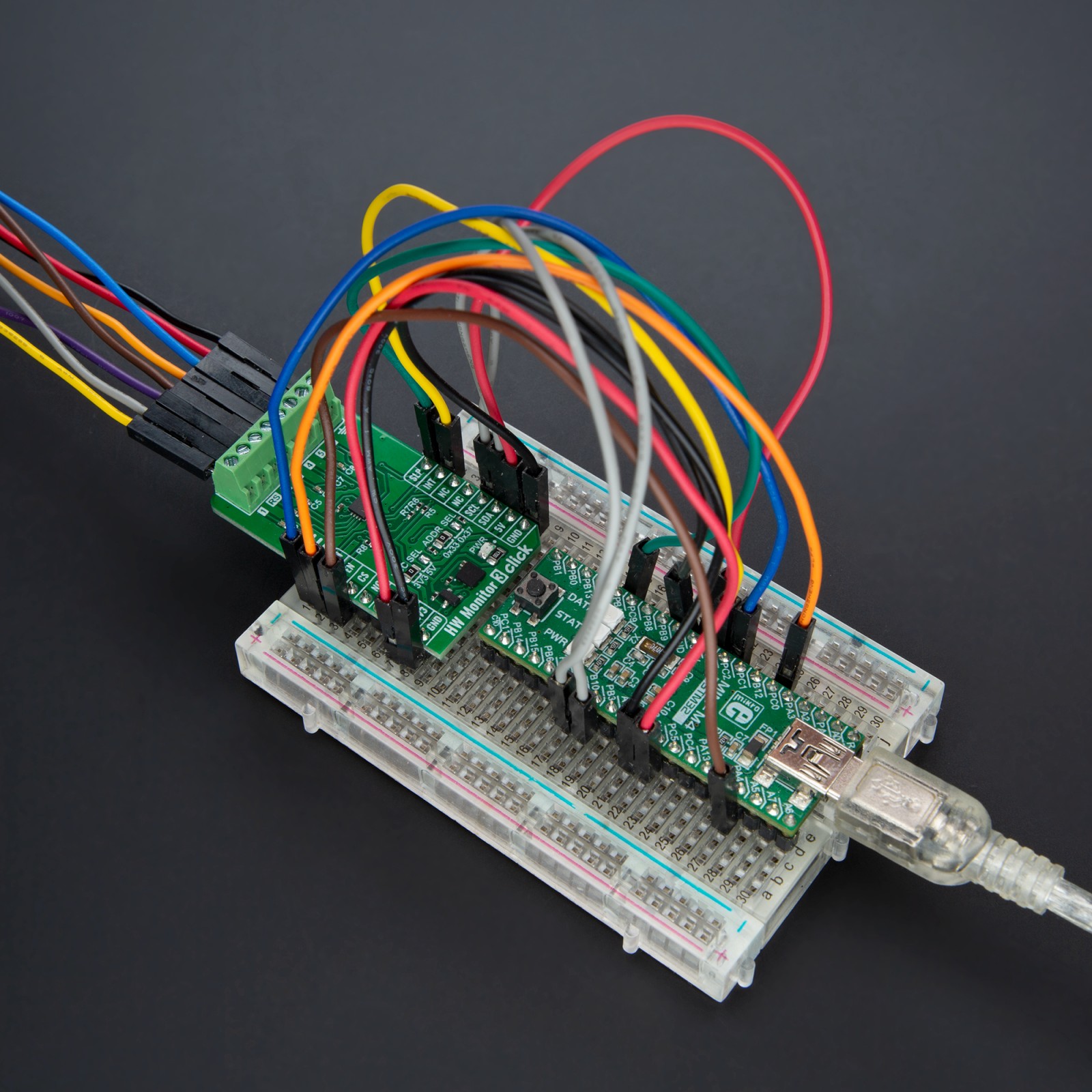
HW Monitor 3 Click uses a standard 2-wire I2C communication protocol to enable the host MCU to control the TPS389006. The I2C interface supports clock frequencies up to 1MHz, with the I2C address selectable via the ADDR SEL jumper. The I2C interface gives flexibility in selecting thresholds, reset delays, glitch filters, and pin functionality. The internal glitch immunity and noise filters eliminate the need for external RC components to reduce false resets resulting from power transients.
In addition to the interface pins, this board uses several pins from the mikroBUS™ socket to enhance its functionality. The EN pin serves as a device-enable signal, allowing activation of the TPS389006 when needed. The INT pin is an active-low open-drain interrupt output, which asserts a signal whenever the monitored voltage moves outside the predefined safe window, providing real-time alerts for critical voltage deviations. Additionally, the SLP pin enables a low-power sleep mode through an active-low signal, optimizing power efficiency when the device is not actively monitoring.
In addition, the TPS389006 offers a sync feature via the SYN pin of the mikroBUS™ socket (sequence logging synchronization across multiple devices) for tagging rails as they come up. When either the EN or SLP pin transitions from low to high or high to low, the sequence logging function becomes active until the sequence timeout expires.
This Click board™ can operate with either 3.3V or 5V logic voltage levels selected via the VCC SEL jumper. This way, both 3.3V and 5V capable MCUs can use the communication lines properly. Also, this Click board™ comes equipped with a library containing easy-to-use functions and an example code that can be used as a reference for further development.
Specifications
Type
ADC
Applications
Ideal for applications in medical devices, industrial robotics, server switches, and motor drivers, where precision, safety, and reliability are critical
On-board modules
TPS389006 – multichannel over/undervoltage I2C-programmable voltage supervisor and monitor from Texas Instruments
Key Features
Six-channel window voltage supervisor and monitor, threshold accuracy across a wide temperature range, fixed window thresholds with selectable steps, Undervoltage Lockout (UVLO), remote sensing for accurate monitoring of high-current core rails, I2C interface, and more
Interface
I2C
Feature
ClickID
Compatibility
mikroBUS™
Click board size
M (42.9 x 25.4 mm)
Input Voltage
3.3V or 5V
Pinout diagram
This table shows how the pinout on HW Monitor 3 Click corresponds to the pinout on the mikroBUS™ socket (the latter shown in the two middle columns).
Onboard settings and indicators
Label | Name | Default | Description |
---|---|---|---|
LD1 | PWR | – | Power LED Indicator |
JP1 | VCC SEL | Left | Power Voltage Level Selection 3V3/5V: Left position 3V3, Right position 5V |
JP2 | ADDR SEL | Left | I2C Address Selection 0x33/0x37: Left position 0x33, Right position 0x37 |
HW Monitor 3 Click electrical specifications
Description | Min | Typ | Max | Unit |
---|---|---|---|---|
Supply Voltage | 3.3 | – | 5 | V |
External Input Voltage | 0 | – | 5.5 | V |
Software Support
We provide a library for the HW Monitor 3 Click as well as a demo application (example), developed using MIKROE compilers. The demo can run on all the main MIKROE development boards.
Package can be downloaded/installed directly from NECTO Studio Package Manager (recommended), downloaded from our LibStock™ or found on MIKROE github account.
Library Description
This library contains API for HW Monitor 3 Click driver.
Key functions
-
hwmonitor3_enable_channel
This function enables the selected monitoring channels. -
hwmonitor3_set_scaling
This function sets the scaling level for the selected monitoring channels. -
hwmonitor3_read_voltage
This function reads the voltage level from all 6 monitoring analog input channels.
Example Description
This example demonstrates the use of HW Monitor 3 Click by reading and displaying the voltage level from 6 analog input channels.
void application_task ( void )
{
hwmonitor3_ch_mon_t ch_mon;
if ( HWMONITOR3_OK == hwmonitor3_read_voltage ( &hwmonitor3, &ch_mon ) )
{
log_printf ( &logger, " CH1: %.3f Vrn", ch_mon.ch1_v );
log_printf ( &logger, " CH2: %.3f Vrn", ch_mon.ch2_v );
log_printf ( &logger, " CH3: %.3f Vrn", ch_mon.ch3_v );
log_printf ( &logger, " CH4: %.3f Vrn", ch_mon.ch4_v );
log_printf ( &logger, " CH5: %.3f Vrn", ch_mon.ch5_v );
log_printf ( &logger, " CH6: %.3f Vrnn", ch_mon.ch6_v );
}
Delay_ms ( 1000 );
}
The full application code, and ready to use projects can be installed directly from NECTO Studio Package Manager (recommended), downloaded from our LibStock™ or found on MIKROE github account.
Other MIKROE Libraries used in the example:
- MikroSDK.Board
- MikroSDK.Log
- Click.HWMonitor3
Additional notes and informations
Depending on the development board you are using, you may need USB UART click, USB UART 2 Click or RS232 Click to connect to your PC, for development systems with no UART to USB interface available on the board. UART terminal is available in all MIKROE compilers.
mikroSDK
This Click board™ is supported with mikroSDK – MIKROE Software Development Kit. To ensure proper operation of mikroSDK compliant Click board™ demo applications, mikroSDK should be downloaded from the LibStock and installed for the compiler you are using.
For more information about mikroSDK, visit the official page.