-
×
 Accel Click
1 × R345.00
Accel Click
1 × R345.00 -
×
 ADC Click
1 × R530.00
ADC Click
1 × R530.00
Subtotal: R875.00


R1,050.00 ex. VAT
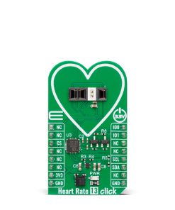
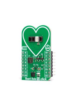
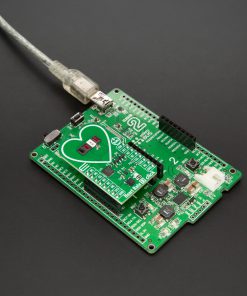
Heart Rate 13 Click is a compact add-on board for precise and reliable vital sign monitoring. This board features the SFH 7074, a biomonitoring sensor from ams OSRAM, with signal processing handled by the ADPD1080 photometric front-end from Analog Devices. The SFH 7074 is optimized for photoplethysmography (PPG) applications, featuring a strong optical signal, an integrated light barrier to prevent crosstalk and high ESD protection. The ADPD1080 ensures accurate signal conversion with a 14-bit ADC and built-in interference rejection, enabling stable measurements even under ambient light conditions. Communication with the host MCU is established via an I2C interface, with additional I/O pins for interrupts and clocking options. Heart Rate 13 Click is ideal for wearable health devices, fitness trackers, and medical diagnostic applications, where real-time biometric data is essential for monitoring heart rate, oxygen saturation, and other vital signs.
Heart Rate 13 Click is fully compatible with the mikroBUS™ socket and can be used on any host system supporting the mikroBUS™ standard. It comes with the mikroSDK open-source libraries, offering unparalleled flexibility for evaluation and customization. What sets this Click board™ apart is the groundbreaking ClickID feature, enabling your host system to seamlessly and automatically detect and identify this add-on board.
Stock: Lead-time applicable.
| 5+ | R997.50 |
| 10+ | R945.00 |
| 15+ | R892.50 |
| 20+ | R858.90 |
Heart Rate 13 Click is based on the SFH 7074, a high-performance biomonitoring sensor from ams OSRAM, designed for precise and reliable vital sign monitoring. This sensor is optimized for photoplethysmography (PPG) applications, providing a strong and accurate optical signal while minimizing the effects of optical crosstalk through an integrated light barrier. Additionally, the SFH 7074 meets stringent ESD protection standards (1.5 kV acc. to ANSI/ESDA/JEDEC JS-001 HBM), ensuring robustness in various operating environments. Due to its advanced design, this sensor is widely used in digital diagnostic applications like wearable devices, fitness trackers, and medical diagnostic equipment, enabling accurate heart rate, oxygen saturation, and other biometric measurements.
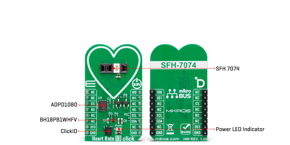
Heart Rate 13 Click incorporates the ADPD1080, a photometric front-end from Analog Devices, to ensure optimal signal processing and high measurement accuracy. This front end is essential for handling the optical signals received from the SFH 7074, as it includes a 14-bit analog-to-digital converter (ADC) and a 20-bit burst accumulator, allowing precise digital conversion of the detected biometric data. The ADPD1080 controls the sensor’s light-emitting diodes (LEDs), stimulating and capturing the reflected optical signals to generate accurate readings. A key advantage of this front-end is its built-in signal processing capabilities, which eliminate the need for external optical filters or DC cancellation circuits. It suppresses signal offset and reduces corruption caused by modulated interference, commonly introduced by ambient light sources, ensuring stable and reliable biometric measurements.
This Click board™ establishes communication with the host MCU through a standard I2C interface of the ADPD1080 operating at 1.8V. Additionally, it features two general-purpose I/O pins (IO0 and IO1), which are connected to the default mikroBUS™ socket’s PWM and INT positions. These pins serve as interrupt sources and offer various clocking options, allowing for greater flexibility in application design and integration with different processing platforms.
The SFH 7074 operates at a 3.3V supply and requires no specific power-up sequence. However, the ADPD1080 photometric front-end requires a 1.8V supply for its analog and digital core to function correctly. To accommodate this requirement, Heart Rate 13 Click integrates a small low-dropout (LDO) voltage regulator, the BH18PB1WHFV, which converts the 3.3V mikroBUS™ power rail into a stable 1.8V supply, ensuring proper operation of the ADPD1080.
This Click board™ can be operated only with a 3.3V logic voltage level. The board must perform appropriate logic voltage level conversion before using MCUs with different logic levels. It also comes equipped with a library containing functions and example code that can be used as a reference for further development.
Type
Biometrics,Heart Rate
Applications
Ideal for wearable health devices, fitness trackers, and medical diagnostic applications
On-board modules
SFH 7074 – biomonitoring sensor from ams OSRAM | ADPD1080 – photometric front-end from Analog Devices
Key Features
Biomonitoring sensor optimized for photoplethysmography (PPG) applications, photometric front-end, strong PPG signal with an integrated light barrier to prevent optical crosstalk, ESD protection, advanced signal processing, and more
Interface
I2C
Feature
ClickID
Compatibility
mikroBUS™
Click board size
M (42.9 x 25.4 mm)
Input Voltage
3.3V
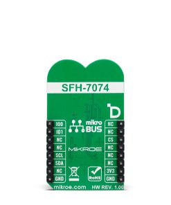
This table shows how the pinout on Heart Rate 13 Click corresponds to the pinout on the mikroBUS™ socket (the latter shown in the two middle columns).
| Notes | Pin | Pin | Notes | ||||
|---|---|---|---|---|---|---|---|
| NC | 1 | AN | PWM | 16 | IO0 | General-Purpose I/O 0 | |
| NC | 2 | RST | INT | 15 | IO1 | General-Purpose I/O 1 | |
| ID COMM | CS | 3 | CS | RX | 14 | NC | |
| NC | 4 | SCK | TX | 13 | NC | ||
| NC | 5 | MISO | SCL | 12 | SCL | I2C Clock | |
| NC | 6 | MOSI | SDA | 11 | SDA | I2C Data | |
| Power Supply | 3.3V | 7 | 3.3V | 5V | 10 | NC | |
| Ground | GND | 8 | GND | GND | 9 | GND | Ground |
| Label | Name | Default | Description |
|---|---|---|---|
| LD1 | PWR | – | Power LED Indicator |
| Description | Min | Typ | Max | Unit |
|---|---|---|---|---|
| Supply Voltage | – | 3.3 | – | V |
| Green Emitter Peak Wavelength | – | 526 | – | nm |
| Red Emitter Peak Wavelength | – | 660 | – | nm |
| Infrared Emitter Peak Wavelength | – | 950 | – | nm |
| Broadband Photodiode Peak Wavelength | – | 940 | – | nm |
| IR-Cut Photodiode Peak Wavelength | – | 635 | – | nm |
Heart Rate 13 Click demo application is developed using the NECTO Studio, ensuring compatibility with mikroSDK‘s open-source libraries and tools. Designed for plug-and-play implementation and testing, the demo is fully compatible with all development, starter, and mikromedia boards featuring a mikroBUS™ socket.
Example Description
This example demonstrates the use of Heart Rate 13 Click board by reading and displaying the PPG measurements which can be visualized on the SerialPlot application.
Key Functions
heartrate13_cfg_setup Config Object Initialization function.heartrate13_init Initialization function.heartrate13_default_cfg Click Default Configuration function.heartrate13_get_pd_data This function waits for the data ready interrupt and then reads data from photodiodes PD1, PD2, and PD3.heartrate13_set_mode This function sets the device operating mode.heartrate13_sw_reset This function executes software reset of the device.Application Init
Initializes the driver and performs the Click default configuration for heart rate measurement.
Application Task
Waits for the data ready interrupt, then reads the PPG measurements and displays it on the USB UART (SerialPlot).
Application Output
This Click board can be interfaced and monitored in two ways:
Additional Notes and Information
The complete application code and a ready-to-use project are available through the NECTO Studio Package Manager for direct installation in the NECTO Studio. The application code can also be found on the MIKROE GitHub account.
| Weight | 17 g |
|---|---|
| Brand | MikroElektronika |