How does it work?
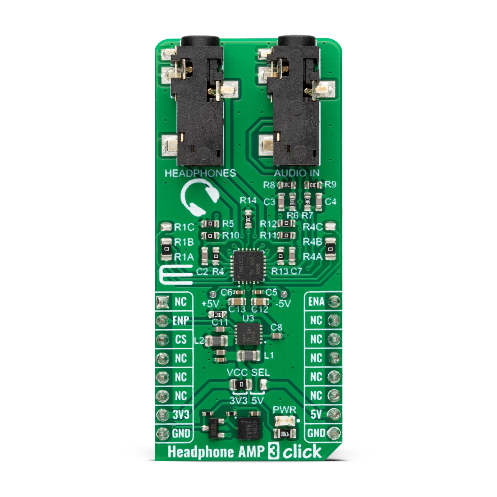
Headphone AMP 3 Click is based on the INA1620, a high-fidelity audio operational amplifier with integrated thin-film resistors and EMI filters from Texas Instruments. The amplifier has a high slew rate, high capacitive-load drive capability, high open-loop gain, low quiescent current per channel, low-power shutdown mode, and thermal shutdown. The internal amplifiers use a unique topology to deliver high output current with extremely low distortion while consuming minimal supply current. The amplifier input pins of the INA1620 are protected from excessive differential voltage with back-to-back diodes; thus, in most applications, the inputs will have no consequences.
The INA1620 has two functional modes: a Shutdown and an Enabled mode. In Shutdown mode, the INA1620 will have minimal power consumption. However, applying signals to the output while in Shutdown mode will parasitically power the output stage of the audio amplifier. While in Enabled mode, the INA1620 uses a few tricks to clean things up. The INA1620 uses efficient electromagnetic interference (EMI) rejection as an immunity to change in offset, thus having a higher EMIRR.
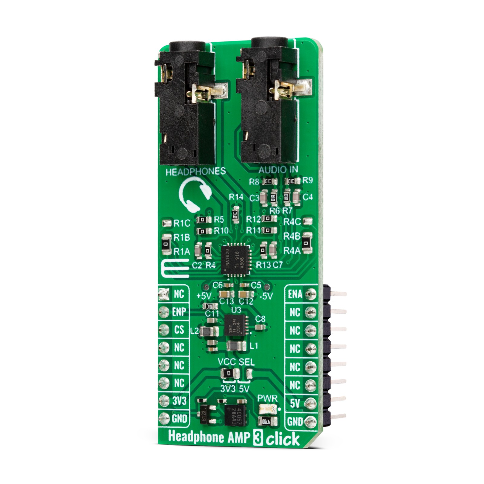
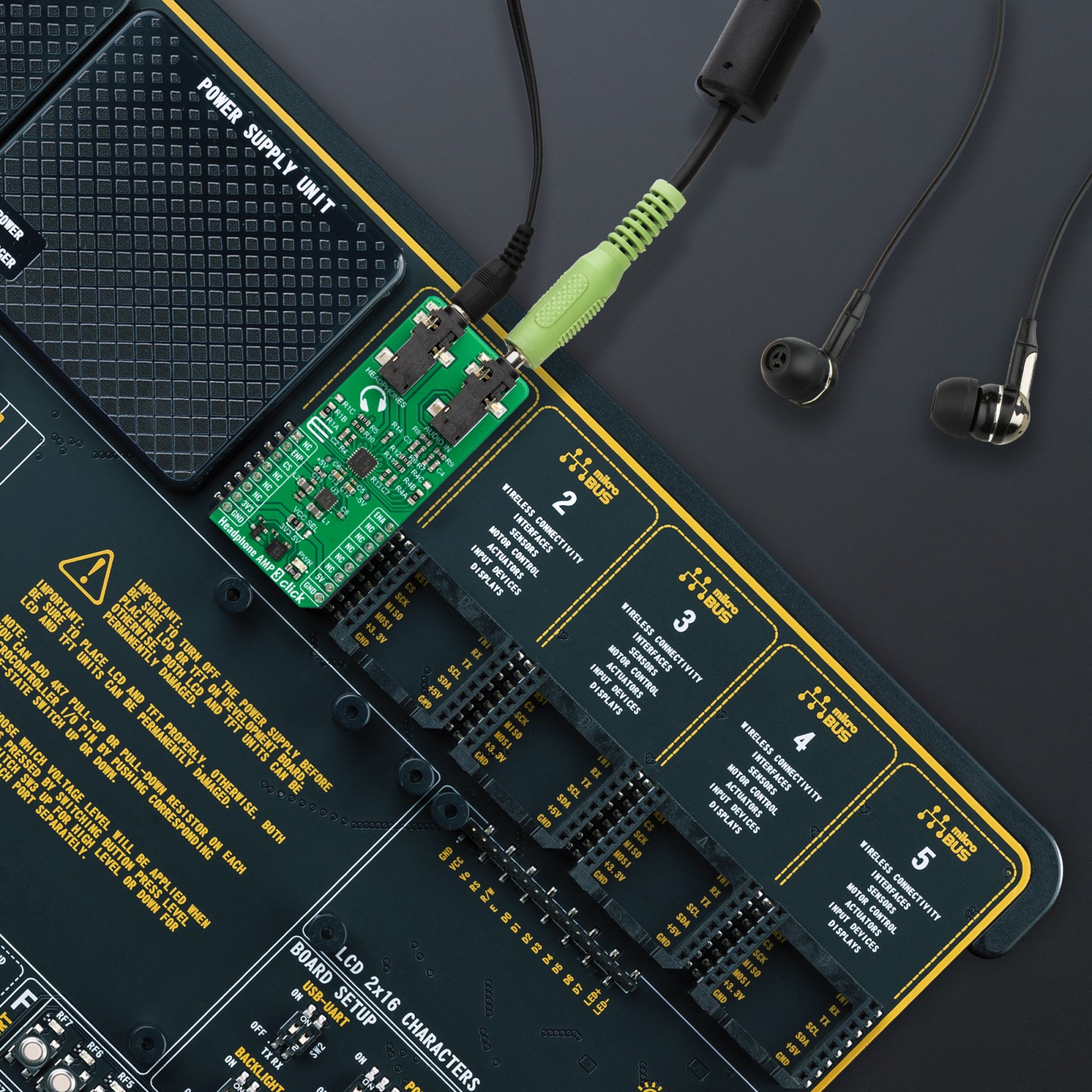
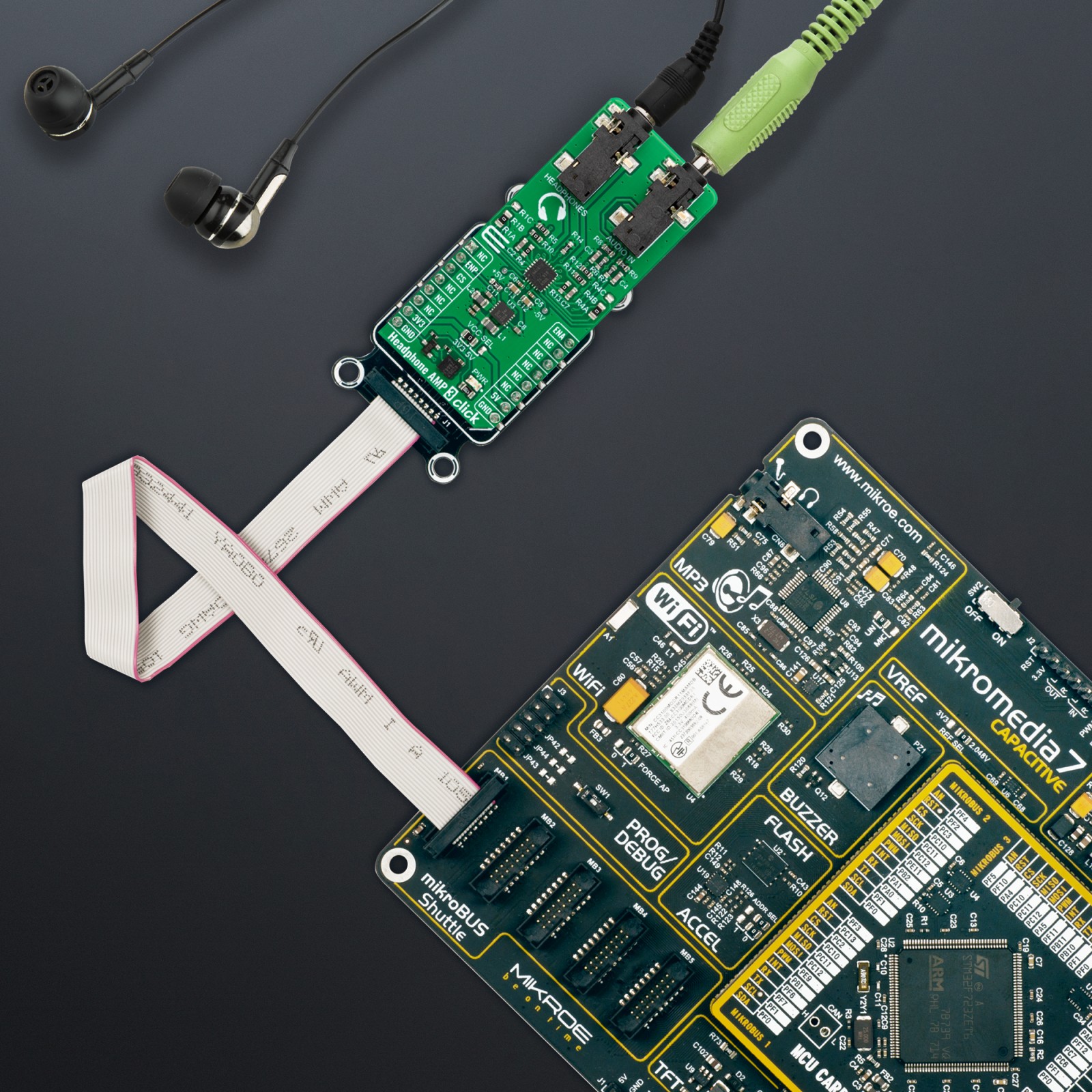
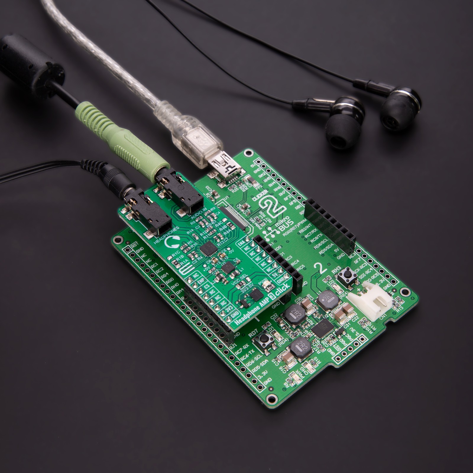
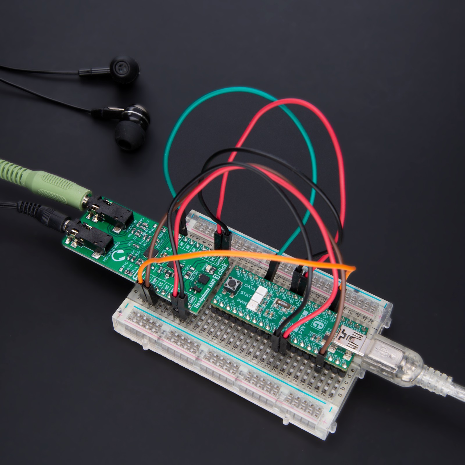
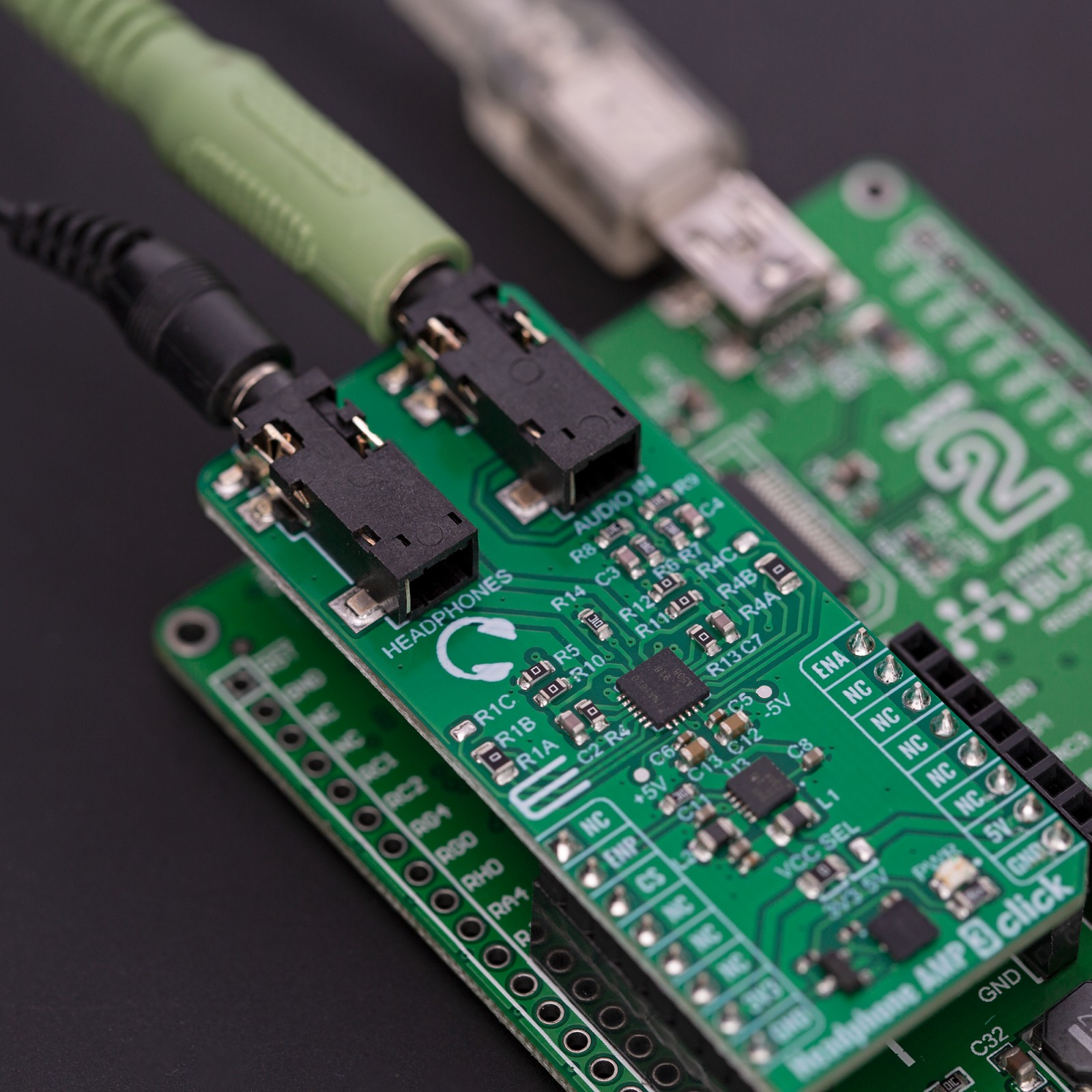
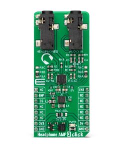
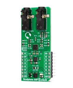
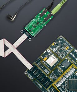
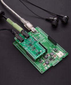
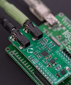
Onboard, there are two 3.5mm audio connectors for connecting the audio source and headphones. The INA1620 uses positive and negative power supplies; on this Click board™, +5V and -5V power supplies are provided by the TPS65133, a ±5V, 250mA dual output power supply from Texas Instruments. The TPS65133 provides fixed positive and negative 5V with ±1% output voltage accuracy and high efficiency. It also includes a boost converter that allows a 3.3V power supply from the mikroBUS™ socket to be used.
The INA1620 has integrated thin-film resistors in four blocks. You can use blocks 1 and 4 to create very high-performance audio circuit configurations. Blocks 2 and 3 are already used and configured in a circuit of this Click board™. All resistors are of 1K, where all A and C are internally connected to a B point. The Headphone AMP 3 Click comes with jumpers to set those configurations. Points R1B and R4B are connected by a trace with the appropriate A points. Cut the trace with a sharp knife and solder jumper resistors to connect B points to C.
The Headphone AMP 3 Click board uses two enable pins as its only connection with the host MCU. The ENA pin enables the INA1620 with a logic HIGH, as the pin is pulled LOW. The ENP is used similarly to enable the TPS65133 boost and buck-boost converter with a logic HIGH as the pin is pulled down.
This Click board™ can operate with either 3.3V or 5V logic voltage levels selected via the VCC SEL jumper. This way, both 3.3V and 5V capable MCUs can use the communication lines properly. However, the Click board™ comes equipped with a library containing easy-to-use functions and an example code that can be used, as a reference, for further development.
Specifications
Type
Amplifier,Signal Processing
Applications
Can be used for the development of high-fidelity (Hi-Fi) headphone drivers, professional audio equipment, audio test, and measurement devices, analog and digital mixing consoles, and more
On-board modules
INA1620 – high-fidelity audio operational amplifier with integrated thin-film resistors and EMI filters from Texas Instruments
TPS65133 – ±5V, 250mA dual output power supply from Texas Instruments
Key Features
Low power consumption, shutdown feature, short-circuit protection, 32Ω load at 150mW, EMI filters, integrated thin resistors for configuration, two 3.5mm audio connectors (IN and OUT), boost and buck-boost power supply onboard with positive and negative output voltage, and more
Interface
GPIO
Feature
ClickID
Compatibility
mikroBUS™
Click board size
L (57.15 x 25.4 mm)
Input Voltage
3.3V or 5V
Pinout diagram
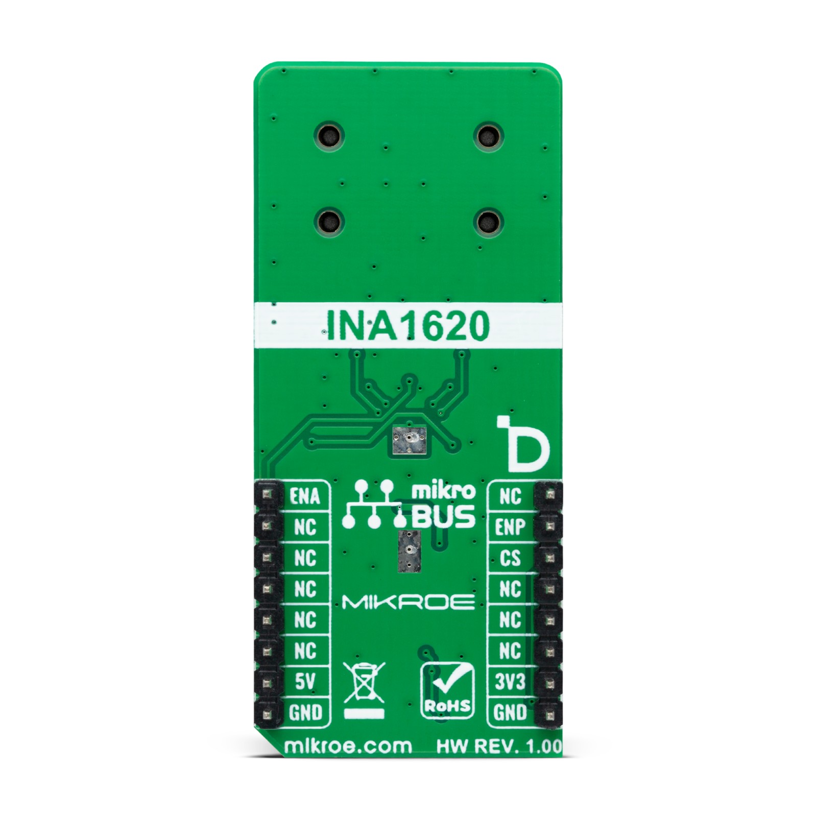
This table shows how the pinout on Headphone AMP 3 Click corresponds to the pinout on the mikroBUS™ socket (the latter shown in the two middle columns).
Onboard settings and indicators
Label | Name | Default | Description |
---|---|---|---|
LD1 | PWR | – | Power LED Indicator |
JP1 | VCC SEL | Left | Logic Level Voltage Selection 3V3/5V: Left position 3V3, Right position 5V |
JP2 | – | Unpopulated | Resistor Pair 4 Selection C/A: Up position C, Down position A |
JP3 | – | Unpopulated | Resistor Pair 1 Selection C/A: Up position C, Down position A |
Headphone AMP 3 Click electrical specifications
Description | Min | Typ | Max | Unit |
---|---|---|---|---|
Supply Voltage | 3.3 | – | 5 | V |
Output Power | – | 150 | – | mW |
Load Resistance | – | 32 | – | Ω |
Software Support
We provide a library for the Headphone AMP 3 Click as well as a demo application (example), developed using MIKROE compilers. The demo can run on all the main MIKROE development boards.
Package can be downloaded/installed directly from NECTO Studio Package Manager(recommended way), downloaded from our LibStock™ or found on Mikroe github account.
Library Description
This library contains API for Headphone AMP 3 Click driver.
Key functions
-
headphoneamp3_enable_power
Headphone AMP 3 power pin setting function. -
headphoneamp3_enable_amp
Headphone AMP 3 amp pin setting function.
Example Description
This library contains API for the Headphone AMP 3 Click driver. This demo application shows use of a Headphone AMP 3 Click board™.
void application_task ( void )
{
log_printf( &logger, " Enabling headphone output rn" );
headphoneamp3_enable_amp( &headphoneamp3, HEADPHONEAMP3_ENABLE );
Delay_ms( 10000 );
log_printf( &logger, " Disabling headphone output rn" );
headphoneamp3_enable_amp( &headphoneamp3, HEADPHONEAMP3_DISABLE );
Delay_ms( 10000 );
}
The full application code, and ready to use projects can be installed directly from NECTO Studio Package Manager(recommended way), downloaded from our LibStock™ or found on Mikroe github account.
Other Mikroe Libraries used in the example:
- MikroSDK.Board
- MikroSDK.Log
- Click.HeadphomeAMP3
Additional notes and informations
Depending on the development board you are using, you may need USB UART click, USB UART 2 Click or RS232 Click to connect to your PC, for development systems with no UART to USB interface available on the board. UART terminal is available in all MIKROE compilers.
mikroSDK
This Click board™ is supported with mikroSDK – MIKROE Software Development Kit. To ensure proper operation of mikroSDK compliant Click board™ demo applications, mikroSDK should be downloaded from the LibStock and installed for the compiler you are using.
For more information about mikroSDK, visit the official page.