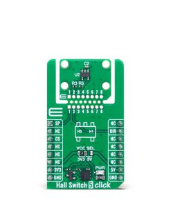
Hall Switch 5 Click
R220.00 ex. VAT
Hall Switch 5 Click is a compact add-on board used for detecting speed and direction of rotation or linear movement. This Click board™ is based on the AH3965, a high-voltage dual Hall effect sensor from Diodes Incorporated. Featuring chopper-stabilized architecture, a temperature-compensated bandgap regulator, and dual outputs for speed and direction, the board ensures stable and accurate performance even in harsh industrial environments. The sensor includes robust protection mechanisms such as a reverse blocking diode, Zener clamp, and undervoltage lockout to maintain measurement integrity. Thanks to MIKROE’s innovative Click Snap format, the board allows flexible implementation and standalone operation. Ideal for use in industrial motors, pumps, white goods, and systems requiring precise motion or position detection.
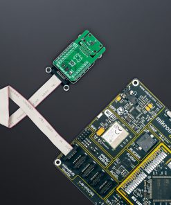
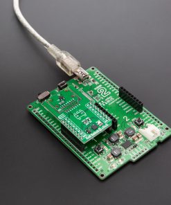
Hall Switch 5 Click is fully compatible with the mikroBUS™ socket and can be used on any host system supporting the mikroBUS™ standard. It comes with the mikroSDK open-source libraries, offering unparalleled flexibility for evaluation and customization. What sets this Click board™ apart is the groundbreaking ClickID feature, enabling your host system to seamlessly and automatically detect and identify this add-on board, alongside a Click Snap feature introducing a new level of flexibility and ease of use.
NOTE: Rotary Magnetic Holder does not come in the same package as this Click board™, but you can find it in our shop.
Stock: Lead-time applicable.
| 5+ | R209.00 |
| 10+ | R198.00 |
| 15+ | R187.00 |
| 20+ | R179.96 |
How does it work?
Hall Switch 5 Click is based on the AH3965, a high-voltage dual Hall effect sensor from Diodes Incorporated designed for precise speed and direction sensing. This sensor uses a chopper-stabilized architecture paired with an internal bandgap regulator to ensure consistent performance across a wide temperature range, enabling reliable operation in demanding industrial environments. The AH3965 generates two key outputs – speed and direction – accessible through the SP and DIR pins, providing a dependable solution for motion detection systems. To protect internal circuitry and ensure robustness, the sensor incorporates a reverse blocking diode and a Zener clamp on the supply line. In scenarios where the supply voltage drops below the minimum operational threshold, the sensor’s undervoltage lockout mechanism activates, freezing operation to prevent measurement errors and ensure that the output is only updated with accurate, validated magnetic data.

The AH3965 is finely tuned to respond to specific magnetic thresholds, with an operating point ranging from -10 to 30 Gauss (typically 10 Gauss), a release point from -30 to 10 Gauss (typically -10 Gauss), and a magnetic offset tolerance of ±15 Gauss. It maintains magnetic matching within ±25 Gauss, ensuring consistent detection performance across applications. This makes Hall Switch 5 Click an excellent choice for a range of motion-related applications, including industrial motors, pump systems, white goods, and systems that require detection of rotational or linear speed and direction, as well as angular position tracking.
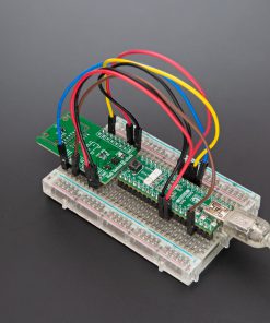
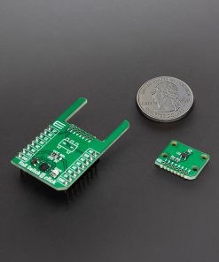
This Click board™ is designed in a unique format supporting the newly introduced MIKROE feature called “Click Snap.” Unlike the standardized version of Click boards, this feature allows the main sensor area to become movable by breaking the PCB, opening up many new possibilities for implementation. Thanks to the Snap feature, the AH3965 can operate autonomously by accessing its signals directly on the pins marked 1-8. Additionally, the Snap part includes a specified and fixed screw hole position, enabling users to secure the Snap board in their desired location.
To support development and testing, Hall Switch 5 Click can be used with an optional rotary magnetic holder, sold separately, which achieves efficient prototyping. This tool features an adjustable shaft fitted with a 6mm diameter magnet that can be aligned directly above the Hall effect sensor. When the magnet moves in the positive x-axis direction – indicating a south pole approaching the sensor’s surface – the south magnetic field strength increases. Movement toward zero indicates a reduction in this field, while movement in the negative x-axis direction corresponds to the north pole approaching the sensor’s marking surface. This precise control and feedback setup enables engineers to quickly evaluate the sensor’s behavior in real-time and streamline their design process.
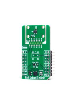
This Click board™ can operate with either 3.3V or 5V logic voltage levels selected via the VCC SEL jumper. This way, both 3.3V and 5V capable MCUs can use the communication lines properly. Also, this Click board™ comes equipped with a library containing easy-to-use functions and an example code that can be used as a reference for further development.
Click Snap
Click Snap is an innovative feature of our standardized Click add-on boards, designed to bring greater flexibility and optimize your prototypes. By simply snapping the PCB along predefined lines, you can easily detach the main sensor/IC/module area, reducing the overall size, weight, and power consumption – ideal for the final phase of prototyping. For more details about Click Snap, visit the official page dedicated to this feature.
Specifications
Type
Magnetic
Applications
Ideal for use in industrial motors, pumps, white goods, and systems requiring precise motion or position detection
On-board modules
AH3965 – high-voltage dual Hall effect sensor from Diodes Incorporated
Key Features
Dual Hall effect sensor for speed and direction detection, chopper-stabilized architecture, internal bandgap regulator for temperature compensation, reverse blocking diode with Zener clamp, undervoltage lockout protection, SP and DIR digital outputs, Click Snap detachable sensor section with fixed screw hole, and more
Interface
GPIO
Feature
Click Snap,ClickID
Compatibility
mikroBUS™
Click board size
M (42.9 x 25.4 mm)
Input Voltage
3.3V or 5V
Pinout diagram
This table shows how the pinout on Hall Switch 5 Click corresponds to the pinout on the mikroBUS™ socket (the latter shown in the two middle columns).
| Notes | Pin | Pin | Notes | ||||
|---|---|---|---|---|---|---|---|
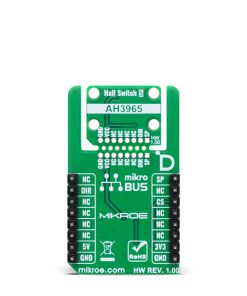
| Speed Output | SP | 1 | AN | PWM | 16 | NC | |
| NC | 2 | RST | INT | 15 | DIR | Direction Output | |
| ID COMM | CS | 3 | CS | RX | 14 | NC | |
| NC | 4 | SCK | TX | 13 | NC | ||
| NC | 5 | MISO | SCL | 12 | NC | ||
| NC | 6 | MOSI | SDA | 11 | NC | ||
| Power Supply | 3.3V | 7 | 3.3V | 5V | 10 | 5V | Power Supply |
| Ground | GND | 8 | GND | GND | 9 | GND | Ground |
Onboard settings and indicators
| Label | Name | Default | Description |
|---|---|---|---|
| LD1 | PWR | – | Power LED Indicator |
| JP1 | VCC SEL | Left | Power Voltage Level Selection 3V3/5V: Left position 3V3, Right position 5V |
Hall Switch 5 Click electrical specifications
| Description | Min | Typ | Max | Unit |
|---|---|---|---|---|
| Supply Voltage | 3.3 | – | 5 | V |
| Operating Point | -10 | 10 | 30 | Gauss |
| Release Point | -30 | -10 | 10 | Gauss |
| Magnetic Matching | -25 | – | 25 | Gauss |
| Magnetic Offset | -15 | – | 15 | Gauss |
Software Support
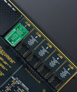
Hall Switch 5 Click demo application is developed using the NECTO Studio, ensuring compatibility with mikroSDK‘s open-source libraries and tools. Designed for plug-and-play implementation and testing, the demo is fully compatible with all development, starter, and mikromedia boards featuring a mikroBUS™ socket.
Example Description
This example demonstrates the use of the Hall Switch 5 Click board by initializing the device and detecting changes in rotational direction and speed. It logs the direction (Clockwise or Counter-Clockwise) and speed in Hertz every second.
Key Functions
hallswitch5_cfg_setupThis function initializes Click configuration structure to initial values.hallswitch5_initThis function initializes all necessary pins and peripherals used for this Click board.hallswitch5_get_speed_pinThis function reads the state of the SPEED pin of Hall Switch 5 Click board.hallswitch5_get_dir_pinThis function reads the state of the DIR pin of Hall Switch 5 Click board.
Application Init
Initializes the logger and the Hall Switch 5 Click driver.
Application Task
Reads the direction and speed pins periodically, logs the rotational direction and calculates the speed in Hz, which is displayed every second.
Application Output
This Click board can be interfaced and monitored in two ways:
- Application Output – Use the “Application Output” window in Debug mode for real-time data monitoring. Set it up properly by following this tutorial.
- UART Terminal – Monitor data via the UART Terminal using a USB to UART converter. For detailed instructions, check out this tutorial.
Additional Notes and Information
The complete application code and a ready-to-use project are available through the NECTO Studio Package Manager for direct installation in the NECTO Studio. The application code can also be found on the MIKROE GitHub account.
Resources
Downloads
| Weight | 17 g |
|---|---|
| Brand | MikroElektronika |